Bonus Content for STLE Members
Rotordynamics
By Nicole Gleeson, TLT Editorial Coordinator | TLT Industry Insights February 2026
Effective rotordynamic analysis ensures more reliable operation, longer machine life, and safer performance.
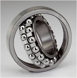
Photo courtesy of FKL India, CC BY-SA 4.0 <https://creativecommons.org/licenses/by-sa/4.0>, via Wikimedia Commons.
KEY CONCEPTS
•
Rotordynamics involves the understanding of rotor-bearing system inertia and flexibility, natural frequencies, imbalance response, and the role of damping and cross-coupled forces on stability.
•
Bearings, seals, and impellers each contribute forces that can be characterized by stiffness and damping coefficients that can strongly influence rotor behavior.
•
Vibration issues can be diagnosed through measurement tools and signature patterns that reveal misalignment, wear, rubs and fluid-induced instabilities.
Meet the Presenters
This article is based on an Industry Insights presented by Aaron Rimpel, Jeff Moore, Thomas Kerr and Jason Wilkes on April 24, 2025, titled
Introduction to Rotordynamic Fundamentals. Industry Insights is a monthly virtual event series available for free to STLE members. These events provide a forum for members to collaborate with STLE industry peers and experts on a specific topic who give a brief presentation, then facilitate conversation by asking discussion questions and providing actionable takeaways. For more information,
click here.
Mr. Aaron Rimpel is a Principal Engineer in the Machinery Department at Southwest Research Institute (SwRI) in San Antonio, Texas, where he has been for over 15 years. He is part of a group within the Rotating Machinery Development Section that analyzes problems associated with various types of machinery, designs and develops rotating machinery components and systems, and develops component test stands for turbomachinery applications. Several aspects of this include rotordynamic analyses, structural/mechanical design and software and diagnostic tool development for data collection and analysis. Rimpel obtained his bachelor of science degree in mechanical engineering from Western Michigan University and his master of science degree in mechanical engineering from Texas A&M University. You can reach him at
aaron.rimpel@swri.org.
Aaron Rimpel
Dr. Jeff Moore is an Institute Engineer in the Machinery Department at SwRI and is experienced in design, testing and troubleshooting high-speed rotating equipment including gas turbines, steam turbines, centrifugal compressors and sCO2 turbomachinery. His research interests are in the areas of turbomachinery rotordynamics, aerodynamics, fluid-structure interaction, advanced seals and bearings, magnetic bearings, computational fluid dynamics, finite element analysis, structural dynamics and sCO2 power cycles. He also possesses skills in machine design, rotordynamics, aerodynamic performance analysis and testing, sCO2 power cycles, vibration testing and failure analysis. Dr. Moore received his Bachelor’s, Master’s, and Doctoral degrees from Texas A&M University. You can reach him at jeff.moore@swri.org.
Jeff Moore
Dr. Thomas Kerr is a Group Leader in the Rotating Machinery Development Section at SwRI. He works on design and testing projects related to turbomachinery applications, with specific interest in supercritical CO2 and energy storage. His experience is in the design, commissioning and operation of rotating machinery test rigs for component-level and system-level research and development. Dr. Kerr received his Bachelor’s, Master’s, and Doctoral degrees from Texas A&M University. You can reach him at thomas.kerr@swri.org.
 Thomas Kerr
Dr. Jason Wilkes is Senior Manager of the Rotating Machinery Development Section at SwRI. His section focuses on improving energy efficiency, reliability and affordability through turbomachinery component design, analysis and testing. These technologies employ a wide range of fluids, power cycles and machinery configurations as required to convert heat into power, power into heat, or store energy for later disposal. Dr. Wilkes’ section has designed machinery and systems that utilize refrigerants, CO2, steam, air, hydrogen and many other working fluids. Dr. Wilkes received his Bachelor’s, Master’s, and Doctoral degrees from Texas A&M University. You can reach him at jason.wilkes@swri.org.
 Jason Wilkes
Modern rotating machinery, including everything from turbines and compressors to gearboxes and pumps, operates under complex physical forces. Understanding these forces and how the rotor system responds to them is the science of rotordynamics, a specialized branch of vibration theory that examines how shafts, bearings, seals and impellers interact during operation.
A recent STLE Industry Insights presentation brought together four experts from Southwest Research Institute (SwRI) to explore both the fundamentals of rotordynamics and its real-world applications. See Meet the Presenters for more information.
Fundamentals of rotordynamics
“Rotordynamics is essentially the specialized application of vibration theory, linear vibration theory most often,” begins Aaron Rimpel, Principal Engineer in the Machinery Department at SwRI. The focus of this article is on lateral rotor dynamics, though he notes that torsional and axial vibration modes also play important roles in advanced systems.
To introduce the basics, Rimpel turns to the Jeffcott rotor model, a simple rotor system often used to demonstrate the fundamentals. The model consists of a rigid disk mounted on a flexible shaft, with the disk’s center of mass offset slightly from the shaft’s geometric center. This asymmetrical configuration produces imbalance when the shaft rotates.
Rimpel explains that Newton’s second law is applied to the Jeffcott rotor model to derive the basic equation of motion for an unbalanced rotor. This particular system has a known solution for the oscillating response at the same frequency as the excitation (shaft speed), while the amplitude and phase of the response varies with frequency. The natural frequency is generally proportional to stiffness and inversely proportional to mass or inertia, according to Rimpel.
He points out that without damping the response would theoretically be infinite. Otherwise, the peak amplitude is inversely proportional to the damping of the system. Regardless, the shaft response lags the mass center by 90 degrees at the natural frequency.
Rimpel explains how damping and stiffness influence how the system behaves. “If [high vibration] amplitude is because we’re operating at a natural frequency, we might be able to shift the natural frequency [to reduce vibration amplitudes] by increasing or decreasing mass or stiffness. We could also add damping to reduce amplitudes.”
Next he introduces the concept of cross-coupling, where forces in one direction occur due to a motion in a different direction. “Generally speaking, this is a destabilizing force because it’s adding energy to the motion,” Rimpel says. “You have many components [applying forces to the shaft] that would be contributing to either its stability or its instability. It’s a matter of which ones are winning essentially that determine whether the system goes unstable or not.”
Finally, Rimpel touches on gyroscopic effects, which arise from the angular momentum of rotating bodies. Forward precession natural frequency increases with speed, while backward precession natural frequency decreases. “The gyroscopic effect is proportional to speed, the angular velocity of the rotating system and the polar moment of inertia,” he notes, showing how these factors complicate the behavior of real machines.
Modeling bearings, seals and impellers
The fundamentals become much more complex once real machine elements are added to the picture. “When you are modeling these rotor systems, you can break the rotor down into different elements,” explains Thomas Kerr, “but you also have to model any connections of the shaft to ground.”
The main connections are bearings, seals and impellers, each of which contributes stiffness, damping and sometimes added mass effects to the system.
Bearings
Bearings support the shaft and allow it to rotate. There are many types of bearings, but they fall into three broad categories: rolling element, fluid film, and magnetic. Ball bearings, one of the most common rolling element bearings, use rollers to transmit the load, and the rollers rotate as well. “Generally, as you increase your speed, your stiffness and damping tend to decrease for ball bearings,” Kerr notes. “As you increase the axial or radial load on your ball bearings, your stiffness and damping tends to increase.” By contrast, fluid film bearings (such as journal bearings) rely on a thin wedge of liquid or gas to generate hydrodynamic pressure that balances the rotor load.
Modeling these bearings often requires solving Reynolds’ classic equation of lubrication, which predicts pressure profiles based on film thickness, viscosity and speed. “Very small changes in your film thickness can lead to really large changes in your pressure profile,” Kerr explains.
Seals
Seals, though often less stiff than bearings, also play a critical role. Their primary purpose is to prevent fluid migration between pressurized regions in the machine, but they can significantly influence vibration in high-pressure systems. Depending on design and operating conditions, seals can dampen vibration or contribute destabilizing cross-coupled forces. Kerr explains, “In general they tend to have lower stiffness and damping than bearings, and so some preliminary system models won’t even include the effects of seals, but in higher pressure systems, the effect from your seals can become quite large.”
Impellers
Impellers, particularly in compressors and turbines, strongly affect rotor stability. Empirical equations, such as those provided by API standards, or more detailed CFD models, can be used to estimate the cross-coupled stiffness terms from impellers. These must be incorporated into rotordynamic models to ensure accurate stability predictions.
Finally, Kerr notes that even the foundation and casing of the machine can influence rotor dynamics. Heavy rotors can excite casing flexibility, lowering natural frequencies. If the foundation stiffness is less than about 3.5 times the bearing stiffness, API guidelines recommend including it in your modeling.
Measuring rotor behavior
Kerr briefly outlines the main measurement techniques used in practice by Dr. Jason Wilkes. The most common are proximity probes (prox probes), which use eddy currents to measure shaft displacement directly at a bearing location. Other tools include accelerometers (measuring acceleration) and velocimeters (measuring velocity), depending on the type of machine and location of interest.
Case histories: Real-world vibration problems
Jeff Moore applies these principles to real-world rotating machinery systems. “When you have a machine shutting down on high vibration, the first question you always want to ask yourself is: is it real vibration?” he emphasizes. Faulty probes or misalignment between pieces of equipment can sometimes mimic vibration problems, so instrumentation must always be verified first.
Once real vibration is confirmed, there are many possible causes:
• Misalignment between coupled machines
• Bearing wear or clearance changes
• Loose foundations or fasteners
• Shaft bow from thermal effects
• Fluid-induced instabilities
• Rubs and impacts
• Imbalance
Misalignment
Misalignment often creates additional radial forces on bearings, leading to high temperatures and elliptical orbits. Moore shared an example where thermal expansion during operation shifted the bearing centerline, causing vibration. Correcting alignment restored normal performance.
Structural resonance
Sometimes the source is not within the rotor itself but in the support structure. Offshore platforms, mezzanine structures or flexible baseplates can all introduce structural resonances that interact with the rotor. Polar plots of amplitude and phase versus speed are useful diagnostic tools in these cases.
Fluid-induced instability
One of the most dangerous issues is sub-synchronous instability, caused when cross-coupled forces (from seals, impellers or worn bearings) exceed the stabilizing damping. “It’s like walking up to a cliff—eventually you fall off,” Moore explains. The vibration amplitude can suddenly increase, damaging seals, bearings or even impellers. Unlike imbalance, instability cannot be fixed by adding balance weights; instead, stabilizing design changes are needed, such as tilt-pad bearings, honeycomb seals or squeeze film dampers.
Oil whirl and oil whip
Fluid film bearings can produce unique phenomena such as oil whirl and oil whip. Oil whirl appears at about half the running speed and tracks with shaft speed. If it locks into a natural frequency, it can develop into oil whip, a violent condition that does not track with speed.
Rubs and bearing damage
Rubs create localized heating and bowing, sometimes leading to oscillating vibration amplitudes known as the Newkirk effect. More severe rubs create impact-type responses, visible as fractional harmonics in frequency spectra. Rolling element bearing damage, by contrast, shows up as characteristic fault frequencies and sidebands, while fluid film bearing damage can result in broadband subsynchronous vibration.
Aerodynamic effects
Large turbomachinery can also suffer from aerodynamic phenomena such as surge or off-design “rumble.” This is not a distinct instability, but more like constant excitation: “It’s like of like tapping with 1,000 hammers,” Moore explains. These events excite rotor natural frequencies through pressure fluctuations and unsteady flow, sometimes violently during emergency shutdowns. Robust surge control systems are essential to prevent damage.
Conclusion
As Moore summarizes, “Vibration is the heartbeat of the machinery.” Careful monitoring, modeling and analysis allow engineers to detect problems early, before they become catastrophic. Ultimately, effective rotordynamic analysis ensures more reliable operation, longer machine life and safer performance. As Rimpel states early in the presentation, “Application will always dictate the dynamics.”
You can reach TLT editorial coordinator Nicole Gleeson at ngleeson@stle.org.