Bonus Content for STLE Members
New horizons for aerospace tribology
By Jeanna Van Rensselar, Senior Feature Writer | TLT Industry Insights February 2024
An in-depth study of lessons learned creates a fresh start for tribology engineering design.

Photo courtesy of xlibber, CC BY 2.0, via Wikimedia Commons.
KEY CONCEPTS
•
Four decades of aerospace tribology lessons learned give a new perspective on the lambda ratio, h/σ.
•
Tribology-by-Design (T/D) provides the theory, tools and methodology for contact interface engineering design targeted to the functional requirements of bearing/gear components in service.
•
T/D interface engineering is a needed discipline in the technology supply chain.
Meet the Presenter
This article is based on an Industry Insights presentation titled
New Horizons for Aviation Tribology with Spin-Off to E-Mobility/Sustainment by STLE member Lavern (Vern) Wedeven on Dec. 13, 2022. Industry Insights is a monthly virtual event series available for free to STLE members. These events provide a forum for members to collaborate with STLE industry peers and an expert on a specific topic who gives a brief presentation, then facilitates conversation by asking discussion questions and providing actionable takeaways. For more information,
click here.
Lavern (Vern) D. Wedeven is president of Wedeven Associates, Inc., Edgemont, Pa., a specialty, high-tech, entrepreneurial company devoted to tribology research and development. He and his associates have developed specialized tribology test machines, test methodologies and analysis tools that link fundamental principles of tribology to service applications. Wedeven is involved in major research projects and consulting that serves aerospace and other industries. He received his bachelor of science degree from Calvin University, bachelor of science degree in mechanical engineering from University of Michigan and doctorate degree from Imperial College, London. Previous employment includes NASA Glenn Research Center, NASA headquarters and SKF USA. He is the author of more than 70 technical papers in tribology and several chapters in reference books. He holds three patents and is the recipient of several awards from STLE, ASME and SAE. You can reach him at
vwedeven@wedeven.com.
 Lavern (Vern) D. Wedeven
This article explains how an in-depth study of lessons learned from four decades of aerospace tribology experience creates new horizons for tribology engineering design.
This article is divided into the following three topics:
1. New horizons for the “lambda ratio” design parameter
2. Tribology-by-Design (T/D)
3. The implementation of T/D.
New horizons for “the lambda ratio” design parameter
The tribology design space of major mechanical systems reduces to a microscale world that must satisfy the functional requirements of macroscale bearings and gears as they carry loads and transmit power within the design domains of propulsion and drive systems (see Figure 1). The focus is on the domain that is defined as “the interface.” It’s all about the interface and the design of the interface for the functional requirements of the components within the mechanical system.
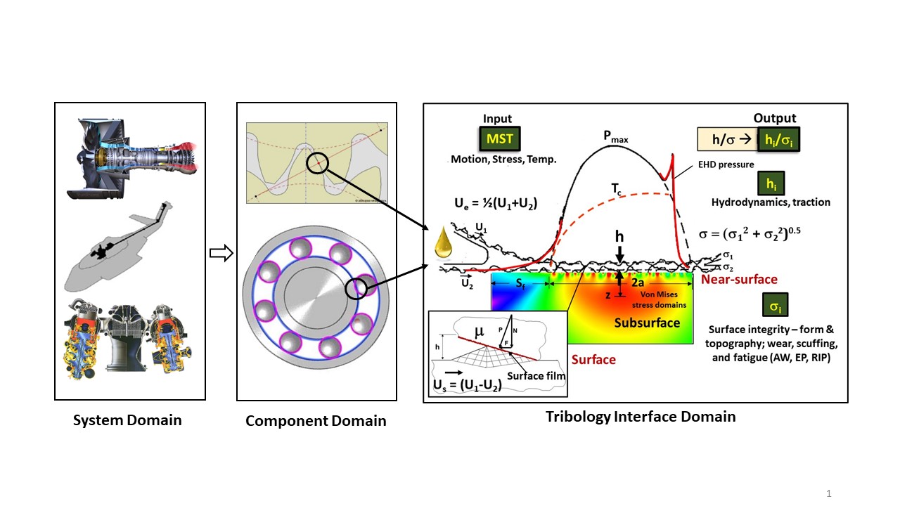
Figure 1. Engineering design domains and relative scales for load-carrying and power transmission.
There are standard methods for design based on forces carried over surface areas resulting in normal and shear stresses. For an elastic concentrated contact, the maximum Hertzian pressure is frequently used as one of the design parameters. The important design feature is how the stresses are distributed over a finite surface region and how the substate surfaces respond to these stresses. The normal and shear stresses are of profound interest.
For typical tribology interfaces, the stress fields of interest are at and near the surface, along with the subsurface stresses associated with the shear within the bulk material. Interface tribology integrity is primarily associated with the stresses at and near the surface. So, the near-surface stress regime or domain is of great interest. The tribology design goal is to keep the near-surface stresses low and not overlapping with the massive subsurface stress field (see Figure 1).
While engineers are accustomed to design actions using stresses and stress cycles, tribology mechanisms are mostly motion-driven. So, the engineering parameters of interest are motions representing the entraining velocity (Ue) to entrain viscous fluids within a converging zone upstream of the contact interface to generate a pressure. The hydrodynamic pressure, resulting from fluid rheological behavior, can be remarkably sufficient to squeeze a minute quantity of oil within the inlet portion of the contact interface to deliver a continuous and highly pressurized film throughout the load-carrying contact interface. The pressurized oil results in a film thickness (h). So, (h) becomes a key design parameter for performance allowing sufficient separation between contacting bodies to accommodate interface shear with low friction within the load-carrying region. The film thickness (h) is easily calculated from elastohydrodynamic theory.
While motion (Ue) entrains fluid into the contact, the shear of the fluid within the interface is associated with the relative sliding motion (Us) within the interface. The sliding velocity (Us) is important with respect to interface tribology design. Motion and the normal stress represented by Pmax determine the stress field within the interface. While normal stress is easily calculated, the shear stress (friction or traction) requires special predictive and modeling methods. Traction within the film and the motion-driven (Us) effects, due to surface topographical features, play an important role in heat generation (Q) and the shear stresses at and near the substrate contacting bodies.
So, the tribology interface design is controlled by input parameters represented by motion, stress, and temperature (MST). These are the key interface design parameters quantifying the interface input. The output has to do with the outcome of the film thickness relative to the combined roughness (σ) of the surfaces. Film thickness (h) and roughness (σ) are vertical dimensions, or dimensions perpendicular to the motion-driven mechanisms that generate hydrodynamic films to accommodate tangential shear with low friction. So, traditional tribology design is based on vertical dimensions resulting from film generation and average roughness height. While these are useful parameters, they don’t sufficiently capture the mechanistic tribology physics associated with fluid streamlines and the surface shear stresses along the interface motions that must be tolerated by the substrates of the contacting bodies.
So, the traditional parameter for design is h/σ (lambda ratio). Wedeven has found that the lambda ratio (h/σ) is not sufficient for design. Accordingly, Wedeven has expanded h/σ to hi/σi. hi and σi represent the tribology interface output. hi represents hydrodynamic mechanisms at the interface for film thickness and traction. The hydrodynamics include whatever mechanisms generate a film, along with the internal friction or traction within that film. This is consistent with the notion that hi and σi represent not just the roughness height (σ), but all the mechanisms associated with surface integrity (σi).
All the mechanisms associated with surface integrity involve the form, shape, or topography of that interface. It involves wear mechanisms, scuffing mechanisms, and fatigue mechanisms. This is consistent with fluid formulations for antiwear (AW) attributes, extreme pressure (EP) attributes and run-in-polishing (RIP). Because of its importance to aerospace and other applications, Wedeven adds RIP to the traditional AW and EP attributes. While these attributes are associated with the oil, they’re also associated with the substrate materials. T/D utilizes the notions of hi and σi in aerospace design. Wedeven’s initial findings are that it works. It also can work for other applications like e-mobility and technical challenges, such as sustainment.
So, the engineering output, represented by hi/σi, is all about getting the interface engineering design to harmonize with the ingredients of that interface. Some magical surface technology is generally not the way to success and innovation. Interface design success is achieved through the harmonization of the contact interface ingredients activated by the MST of the component’s operational duty cycle. The output, represented by hi/σi, must satisfy the functional requirements of the targeted component during operation. Wedeven does not replace the traditional h/σ. He expands h/σ to hi/σi to capture the mechanistic processes that control lubrication and traction (hi) and surface integrity (σi).
Tribology-by-Design (T/D)
The decades of the 1970s and 1980s produced amazing accomplishments in aviation propulsion and drive systems. Gas turbine engine technologies embodied in oil formulations and bearing/gear materials developed rapidly. In the late 1990s, engine companies started pushing hard for higher temperature lube systems requiring oils with higher thermal stability. The oil suppliers responded. In the meantime, the mechanical systems engineers focused on improved fatigue life of bearing steels, along with corrosion resistance, which they did successfully.
Developments in advanced oils and component steels were conducted independently. While the desired attributes were enhanced, the hidden risk in doing this was the impact on the broader mechanisms and attributes associated with hi/σi. Unfortunately, the actions taken to formulate oils for higher temperatures, along with component materials with better fatigue life and corrosion resistance, significantly reduced the interface ingredients needed for surface integrity σi. Legacy oil formulations and bearing/gear steels had inherent attributes for boundary films for AW, EP and RIP. To overcome these deficiencies, solutions were sought through improvement in surface roughness, etc. Unfortunately, they were not successful.
Leading up to the year 2000, some new oil formulations had to be pulled from service. In addition, the industry had to go through engine redesign because advanced engine designs relied on advanced materials with better fatigue life, which couldn’t be realized. This experience, mostly under the public radar, resulted in two actions:
1. Development of the mindset of “leaving no attribute behind”
2. Utilization of the NASA concept of Technology Readiness Level (TRL)1 (see sidebar).
Technology readiness levels (TRLs)
Technology readiness levels (TRLs) were developed by NASA to evaluate the technology readiness of proposed programs. The following commonly accepted TRL levels, adopted by the EU, closely match the original NASA TRLs.
1. Basic principles observed
2. Technology concept formulated
3. Experimental proof of concept
4. Technology validated in lab
5. Technology validated in relevant environment
6. Technology demonstrated in relevant environment
7. System prototype demonstration in operational environment
8. System completed and qualified
9. Actual system proven in operational environment.
TRL reduces risk in the design of major mechanical systems offering deliberate development stages for maturity from fundamentals to final application. There are nine levels of maturity to reduce risk. While TRL did reduce the risk, it was slow, costly, and not conducive to innovation. While TRL is necessary to reduce risk, Wedeven had to find a way to work within the TRL system but with much greater efficiency and innovation. Additionally, the tribology interface design needed to be based on hi/σi. An in-depth study of lessons learned resulted in the notion of T/D.
T/D provides solutions to targeted component interfaces through the application of six items:
1. Theory
2. Test/analysis tools
3. Methodology
4. Process
5. Strategy
6. Solution outcome.
The first three items are illustrated with a T/D roadmap in Figure 2.
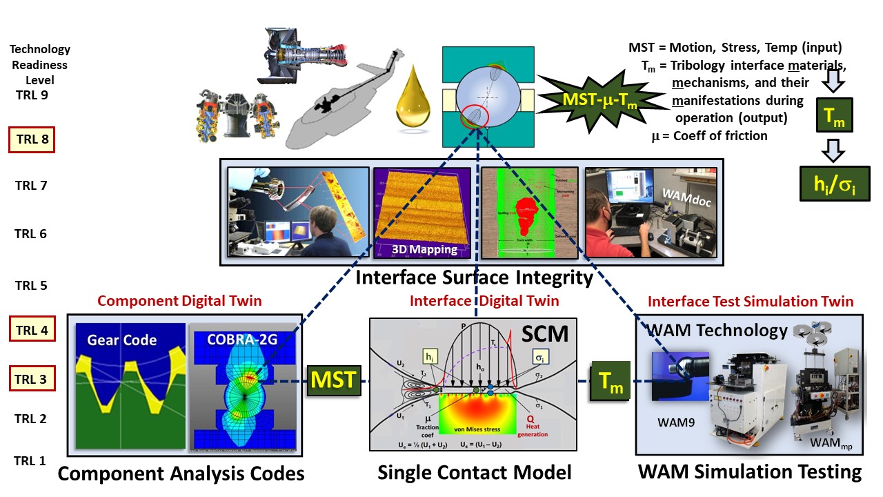
Figure 2. T/D roadmap, tools, and methodology within the TRL design system.
T/D addresses the functional requirements of a targeted component contact interface. The T/D theory from first principles utilizes engineering parameters representing the MST. These input parameters activate the contact interface tribology materials, the controlling mechanisms, and their manifestations (Tm) during operation through the interface friction (µ). The theory reduces all contact interfaces interactions to MST-µ-Tm.
Specialized test and analysis tools are used for surface integrity analysis. Component analysis codes are used to extract the required MST parameters. Simulation testing is conducted with special single contact high-speed test machines. A single contact model (SCM) is used to conduct all the interface hi calculations, including analysis on an asperity scale from a 3D topographical input file. The T/D tools provide a component analysis digital twin, an interface test simulation twin, and an interface digital twin.
The T/D methodology extracts the targeted MST-µ-Tm from the targeted component (TRL 8) and addresses the tribology interface design at a more workable TRL 3 and TRL 4 level. TRL 3 testing and analysis are for tribology performance information. TRL 4 testing and analysis are for component interface simulation and performance design and validation. The theory, test/analysis tools, and methodology enable rapid response, along with innovative and timely solutions.
Solutions are achieved through a process that first addresses hydrodynamic (hi) mechanisms. With current traction models all interface film thickness, traction, thermal and stress analysis for design can be calculated. The process then moves to T/D surface integrity (σi) interface design using information gathered from TRL 3 testing and modeling.
Implementation of T/D
The next step is developing a strategy to meet the functional requirements of the targeted component. This is accomplished through fulfillment of MST-µ-Tm requirements for performance, as well as cost-effective manufacturing and service operation. It starts with a targeted mechanical system, its functional requirements and how those requirements are translated to the components for carrying loads and transmitting power. That leads to the domain of the tribology interface, which is controlled by MST parameters. These are the engineering input parameters. The input parameters activate the interface ingredients, which need to be harmonized or designed in a way that satisfies the requirements for hi and σi (see Figure 3).
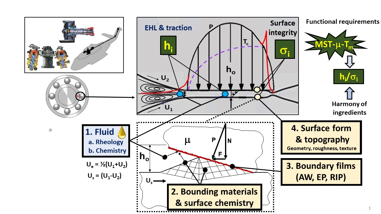
Figure 3. The tribology interface design ingredients to fulfill component hi/σi functional requirements.
There is a design process for fulfilling functional requirements. Wedeven always starts with the fluid and its rheology as it transits the contact interface. The fluid is the lifeblood, and its internal friction is the heartbeat of its mechanistic performance. This is essential for aviation where the functional requirements of components demand durability and reliability for on-wing operation of commercial aircraft for 10 to 20 years.
The only way to do that is through load-carrying and shear accommodation through the generation of a film (hi). The sheer resistance of that film should be as low as possible enabling high efficiency in terms of friction. Once the shear stresses at the bounding surfaces are determined, the design action addresses the interface ingredients for σi. The ingredients, other than the fluid film (hi) and its internal friction (traction), involve contacting body A and body B, their mechanical properties in the near-surface region, along with the chemical properties at the surface (boundary films). The chemical properties at that surface, combined with the chemistry of the oil, where the oil transports that chemistry to the surface, reacts at that interface, creates its own internal friction, and ends up with the boundary film.
It is important to recognize that there is no tribology action occurring until there is motion. So, the implementation of T/D requires designing things on the fly. That is what makes the engineering design of contact interfaces difficult. Experimentation and test simulations are required to find out what works and what doesn’t work. From a design process perspective, the final action to achieve the desired functional requirements is through surface form and topography (surface geometry, roughness, and texture).
The design strategy is derived from the application, generally guided by high speed or low speed. T/D strategy is critically related to cost and ability to control the quality. The design process of T/D enables solutions to be found on the laboratory scale, before having to take on the risk of launching major mechanical systems into testing. So, the solutions and the process create a bridge between the lower TRL science and technology and the implementation to higher TRL applications.
T/D is the way to bridge the gap between the material suppliers and OEMs through engineering of the contact interface. The discipline of tribology contact interface engineering design seems to be missing, particularly with respect to simulation, testing, design, and analysis. All of this must be carried out through the component suppliers, where component designs are consistent with hi/σi. That’s the new horizon for tribology design. T/D is a very important ingredient in the technology supply chain, and it’s a discipline that is not very mature. Wedeven sees new horizons in this area for tribology.
Implementation of T/D for solution outcome requires the engagement and education of the entire technology supply chain. The supply chain consists of six tiers involving R&D, material suppliers, tribology interface engineering, component suppliers, OEMs, and users (or operators) (see Figure 4). New horizons in aerospace tribology have T/D engineering as an enabling contributor to the technology supply chain. T/D is implemented through 9-6-6; nine TRL technology maturity levels, six T/D actions, and engagement of six tiers of the technology supply chain.
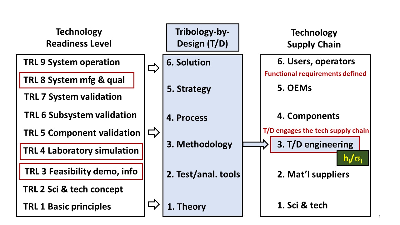
Figure 4. The role of T/D interface engineering in the technology supply chain.
REFERENCE
1. The TRL methodology was originated by Stan Sadin at NASA headquarters in 1974. The concept was formalized in 1980.
Jeanna Van Rensselar heads her own communication/public relations firm, Smart PR Communications, in Naperville, Ill. You can reach her at jeanna@smartprcommunications.com.