KEY CONCEPTS
•
Most electrical damage in electric motors or wind turbines is induced in the bearings.
•
Induced magnetic fields, voltages and currents lead to a variety of electrical discharges and related damage.
•
Tribofilm disruption may occur, but damage due to this is minor in comparison to discharge-related damage.
Tribology in an electrical field is not new, as generators and electric motors have been around for around 140 years. However, new challenges have emerged with the energy transition, most notably the growth of wind turbines (generators) and electric motors for passenger cars and light commercial vehicles.
The bearings in wind turbines are subject to many sources of abuse, including buffeting by varying winds, high humidity and both daily and seasonal temperature variations. But this article will focus on the damage that can be wrought by electric fields and the resulting discharges. Damage can be catastrophic and is described as electrically induced bearing damage (EIBD). This covers a wide variety of damage modes, most of which take place with an oil film present, so lubrication is hydrodynamic. However, the electric fields can also affect tribofilm formation.
“Current” affairs
It’s been over 190 years since Hippolyte Pixii built the first practical alternating‑current dynamo,
1 shortly after Michael Faraday’s 1831 discovery of electromagnetic induction. The first tram/streetcar and first direct current (DC) mainline train both ran in Berlin around 1880,
2,3 and the first alternating current (AC) trains were in service by the turn of the 20th century.
4 Over time, many diesel-powered rail vehicle designs migrated to the diesel engine generating electricity that powered electric traction motors.
So, with such history, and with so many electric motors in industrial applications, what makes the study of the motors in modern electric vehicles (EVs) and generators in wind turbines worthwhile?
“The unique features of wind turbines are their sheer size as well as the forces they experience,” says STLE Fellow Peter Lee of Southwest Research Institute. “Electrically there are discharge events and stray currents caused by the process of converting the AC produced by the generator to DC for transmission or battery storage. These stray currents can disrupt tribofilm formation and accelerate lubricant degradation, which, in turn, may generate hydrogen from the water contamination.” The electrical effects, coupled with high contact pressures (due to, say, wind gusts or emergency stopping) and the presence of hydrogen are implicated in the formation of white etching cracks.
Lee continues, “Electric drive units (EDUs) for EVs are not running directly AC or DC as in the earlier street cars and trains of the 1800s. The energy is stored in a DC battery while the motor requires an AC supply. This requires the conversion of the DC to AC using an inverter, which mimics the AC supply, and this process is what causes discharges, which are what damage the bearings. These discharges flow through the bearing as this is the most direct path from charge to ground the EDU.”
Stray and induced currents
Bearing currents are high-frequency currents that are caused by voltage on the motor or generator shaft, which drives a discharge current through the shaft bearings. In EV traction motors, the primary driver of these parasitic currents is the variable frequency drive (VFD) or inverter. The generation of these pulsed electrical waves and the associated spiking of currents and voltages has been covered in an earlier TLT article.
5
When an ideal three-phase sine wave is generated, the sum of voltages equals zero
(see Figure 1).
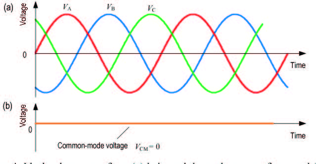 Figure 1. Ideal voltage. Figure courtesy of Southwest Research Institute.
VFD power consists of rapid pulses where the input is never perfectly balanced. This results in a stepped common mode voltage and a series of discharges
(see Figure 2).
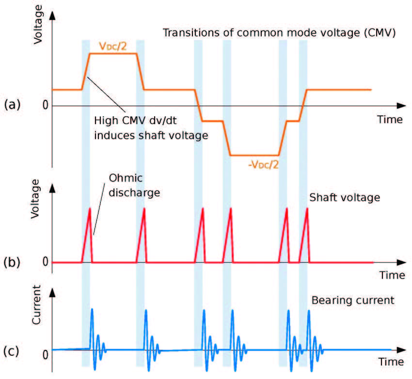
Figure 2. Transitions of common mode voltage (CMV). Figure courtesy of Southwest Research Institute.
Similar imbalances occur in the generator of a wind turbine. The generator produces a relatively smooth, sinusoidal, three-phase AC output that is then converted to DC. A common mode voltage occurs because the converters use pulsed wave modulation (PWM) switching, which produces a much less smooth waveform.
Motors
There are three types of bearing current. Circulating currents are inductive. They originate from the common mode currents that induce an asymmetric magnetic flux around the motor. This asymmetric flux, in turn, creates shaft voltages, which drive very high frequency, aggressive currents circulating through the motor. STLE member Rai Notay, of Lubrizol in the UK, says, “Circulating bearing currents flow due to high-frequency flux produced by common mode currents.”
The two destructive types of bearing current in well-grounded VFD-fed motors are capacitive electro discharge machining (EDM) and high-frequency circulating current. “I prefer the term EDD or electric discharge damage, as it better describes what is going on,” says Notay.
The voltage that gives rise to the EDM current is between the motor’s rotor and shaft. This shaft voltage discharges by arcing through the bearings to the frame
(see Figure 3a). This is present in all electric motors, regardless of size.
6
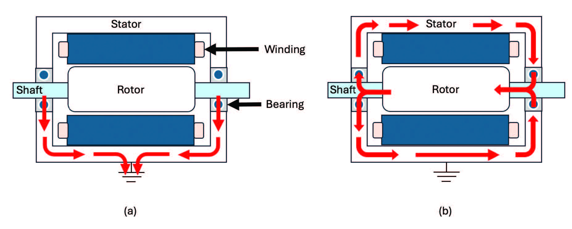 Figure 3. Common bearing currents in electric motors: (a) capacitive discharge from the shaft through the bearings to the motor frame, and (b) high frequency circulating currents.
The flux of a high frequency circulating current
(see Figure 3b) is usually only strong enough to cause an issue in larger motors exceeding 75kW. The current circulates from the shaft to the frame through one bearing, and from the frame back to the shaft at the other, damaging both bearings simultaneously. The combined effect is an asymmetric current.
These mechanisms give rise to the overarching term EIBD.
Rotor to ground currents are highly undesirable. With similar origins to circulating currents, they flow through the shaft into the gearbox, which can lead to very expensive failure.
Failures
“There are not a huge number of EDU failures being seen in the market,” says Lee. “This is due to both over-engineering [of the EDUs] and control of the market.” Notay agrees, both sources citing the gearbox as a robustly engineered item in most modern EVs.
“We have seen failures on rigs, but not very many,” says Lee. “The majority of concerns are not coming to fruition.” For example, “We ran a new EV on a chassis dynamometer for 150,000 miles and everything looked in extremely good condition.”
Electrically induced bearing damage
“Early EVs had issues of EIBD in bearings,” says Notay. “I have heard of one significant problem with stray currents in an electrified transmission having a pathway to the wheel bearings.” As the market has grown, more examples are coming to light.
Electrical effects could play a role in the formation of white etching cracks in wind turbines. Notay and others have suggested a combination of thermal and load stresses within an electric field, and possibly some hydrogen embrittlement has been cited as being a potential cause. Some damage modes due to internally generated currents are listed in Table 1.
7,8
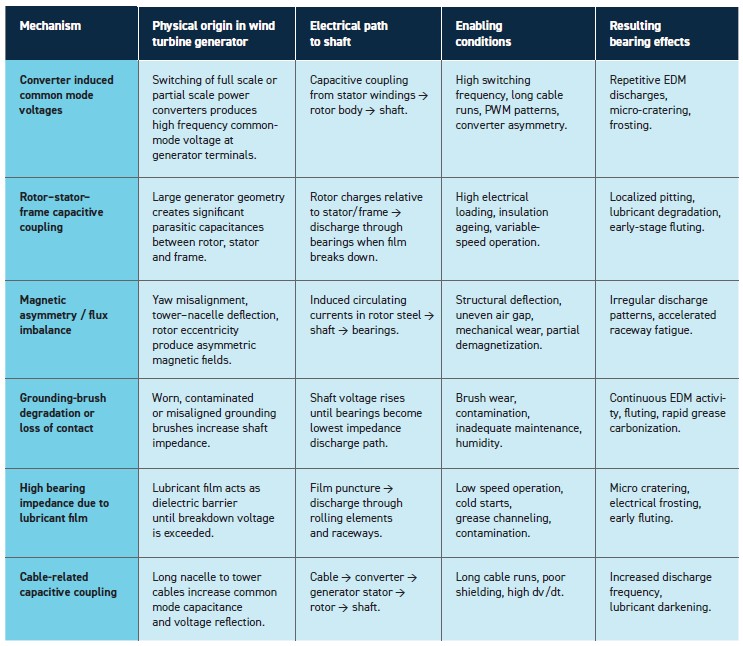
Table 1. Damage modes due to internally generated currents
However, EIBD itself is not listed as a cause of a significant number of failures in wind turbines, according to the National Renewable Energy Laboratory and Argonne National Laboratory.
9 The forms of EIBD listed in Table 1 don’t have the prominence of white etching cracking.
7,8
Damage
There are several recent reviews investigating damage that occurs in both the rolling element and the raceway.
10,11 “The main damage happens when an electrical arc is formed across two surfaces, causing damage to both surfaces,” STLE member Marc Ingram, Ingram Tribology Ltd., explains. “The surfaces will then be damaged, normally with small pits, and small hard particles are also generated. A few different failures can then happen, such as pitting, fluting and normal wear. An arc event can be singular or multiple.”
The first visible and audible damage due to arc discharge is frosting. “Frosting results from small-scale arcing,” says Notay. This could be up to tens of thousands of times per second. “The metal in the raceway melts and is rapidly quenched as it’s in a lubricated environment. This changes the material structure and surface roughness, giving rise to a dull, matte grey appearance, due to multiple pits that also have a change in mechanical properties.”
The discharges can also degrade and oxidize the bearing lubricant which, in combination with the frosted surface, produces increased friction and noise. Eventually, the bearing may develop stripes called fluting, resulting in even more noise.
Fluting
(see Figure 4) is probably the most visually striking form of failure, according to Notay. “You tend to see damage in the raceway due to the pathway of current. Fluting develops after frosting and is caused by periodic discharges combined with cyclic loading and ultimately shortens the bearing life.”
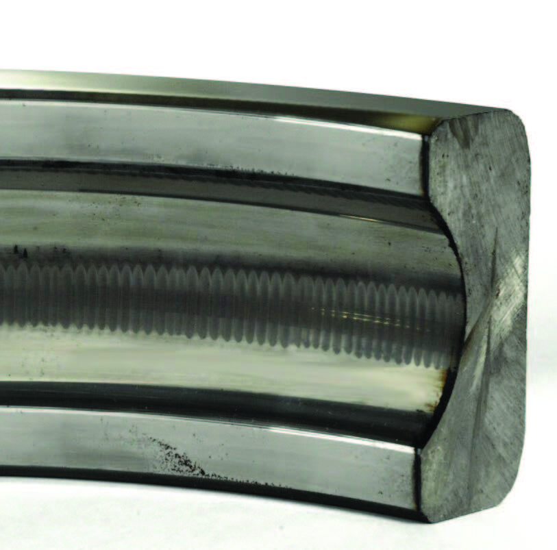 Figure 4. Fluting is probably the most visually striking form of failure. Figure courtesy of Electro Static Technology™, an ITW Company.
Vibrations due to fluting generate a characteristic sound. By the time fluting is audible, bearing failure is imminent.
The voltages and currents required for damage are small. Ingram notes, “From my perspective the most severe damage will be caused by electrostatic discharges (ESD), which can occur under full film conditions and mixed regimes, usually above about 1 amp of current.”
Notay observes that there are many studies on a wide variety of electrical conditions. “We’ve done some tribology testing using an electrified ball on disc machine and found you only need a potential difference of 1V that can cause sufficient damage between the components if breakdown occurs, but there are many studies with greater amounts of potential difference. The oil film thickness in such EHD contacts is very small, hence only a small voltage is required to arc across the contact.”
The experts were split on the question of whether damage occurs away from the bearings. According to Notay, “Rotor to ground currents could potentially cause gear damage if the stray currents are not supressed accordingly. As soon as a gear gets pitting damage, this leads to reduced rolling contact fatigue life and eventually failure. So, effectively the transmission would need to be overhauled or changed. But in reality, the bearings take most of the brunt of the stray current in applications.”
Lee is less convinced. “Does electrically induced damage happen in gears? Not really.”
Effects on tribofilms
As a bearing should always be lubricated in the elastohydrodynamic/full film regime the effect of electric currents on the formation of tribofilms is not so critical. Cylindrical or tapered roller bearings do have some tribofilms.
“We always see more wear when running under DC conditions,” says Lee. Conceptually, this is easy to envisage: an applied voltage acts for or against the interaction of an additive with a surface, whether that be an electrostatic interaction or chemical reaction. Polar molecules in an oil can be aligned by the DC. However, with AC they are unable to align in the same way since the desired alignment is constantly changing.
Notay believes electrically induced discharges potentially disrupt tribofilm formation by repeatedly breaking down the lubricant surface chemistry, preventing stable antiwear films from forming and instead promoting unstable, non protective reaction layers and surface melting. In oil‑lubricated bearings subjected to stray currents, electrical discharges can occur across the elastohydrodynamic lubricant film once its dielectric strength is exceeded. These discharges cause localized heating, dielectric breakdown of the lubricant and transient vapor or plasma formation. The resulting loss of electrical insulation allows current to pass directly through the rolling contact, leading to surface melting, EDM cratering and eventual metal‑to‑metal interaction.
For Ingram, “We also see interesting effects of stray and parasitic currents—especially at lower currents/voltages in the mixed and boundary regime, where electrostatic discharges are much less of a concern. These can have large effects on the formation of the tribofilm, either hindering it or enhancing it. The secondary effects are changes to the friction between the surfaces, and the tendency for micropitting and pitting. Also electrically induced subsurface pitting, sometimes termed electrically induced white etching cracks (eWEC), can occur—where lower currents are known to disrupt the tribofilm and probably accelerate the degradation of the steel—accelerating the formation of pits."
Study
“All the field issues I have seen can be mimicked in the laboratory, usually quite simply,” says Ingram. “There are various techniques of isolating rotating shafts and applying known currents through normal tribology test rigs. There are even some off-the-shelf systems that have been commercialized in the past few years. We use a mixture of homemade systems and off the shelf electrical tribometers. We have plenty of ways to damage surfaces and analyze them.”
“We can drive where the damage takes place on, say, ball on disc equipment,” says Notay. “We can adjust polarity, frequency and wave form. Most published work is currently DC [as research groups] try to understand what is going on. Ultimately, I want to mimic the contact, as closely as possible: speed, load, temperature, voltage and contact dynamics.”
The first commercial electrified ball-on-disc rig has now come to market.
12 Forthcoming Southwest Research Institute projects include helping manufacturers electrify a micropitting rig and a commercial block-on-ring rig. Further developments in train include helping rig manufacturers modify equipment to produce AC and DC across the contact.
Electrified tribological equipment isn’t just used to study model systems for EV motors. Argonne National Laboratory is one of several institutes with test rigs custom modified to do testing with applied electrical currents. “All of these [at Argonne] are based on a three ring on roller contact configuration,” says STLE member Aaron Greco, the Wind Energy Laboratory program manager at Argonne National Laboratory. “We mostly use these for white etching crack testing, but we can also do a variety of different types of electrical testing.”
There are drawbacks with rig studies. Notay gives an example: “As soon as you create a single pit on a test component, you can create a local hot spot for arcing. So, frosting with its multiple adjacent pits is difficult to mimic repeatably. In such tribometers the film thickness changes even under steady state conditions, so damage can be different at different points on the track on what should be a continuous contact patch.”
Full-scale bearing test rigs are now available with electrical control. These induce damage over minutes or hours, rather than seconds with other rigs.
Mitigation
According to Ingram, options to mitigate ESD across a lubricating EHD film are limited. “If we continue to use hydrocarbon fluids, the oil breakdown voltage will continue to be in the 10-40kV/mm range. So, there is a fundamental limit if we have two steel surfaces separated by a hydrocarbon film. We can’t prevent an arc, once the potential difference rises high enough. Practically the steel parts could be grounded—such as the rotor in a motor to prevent the charge build up. A conductive part could be added, such as a conductive seal, to allow the passage of the current, away from the tribology contact. Conductive grease could be used in some situations. Another approach is to not let an electrical discharge happen by using insulating parts, such as ceramic bearings
(see Figures 5-7).”
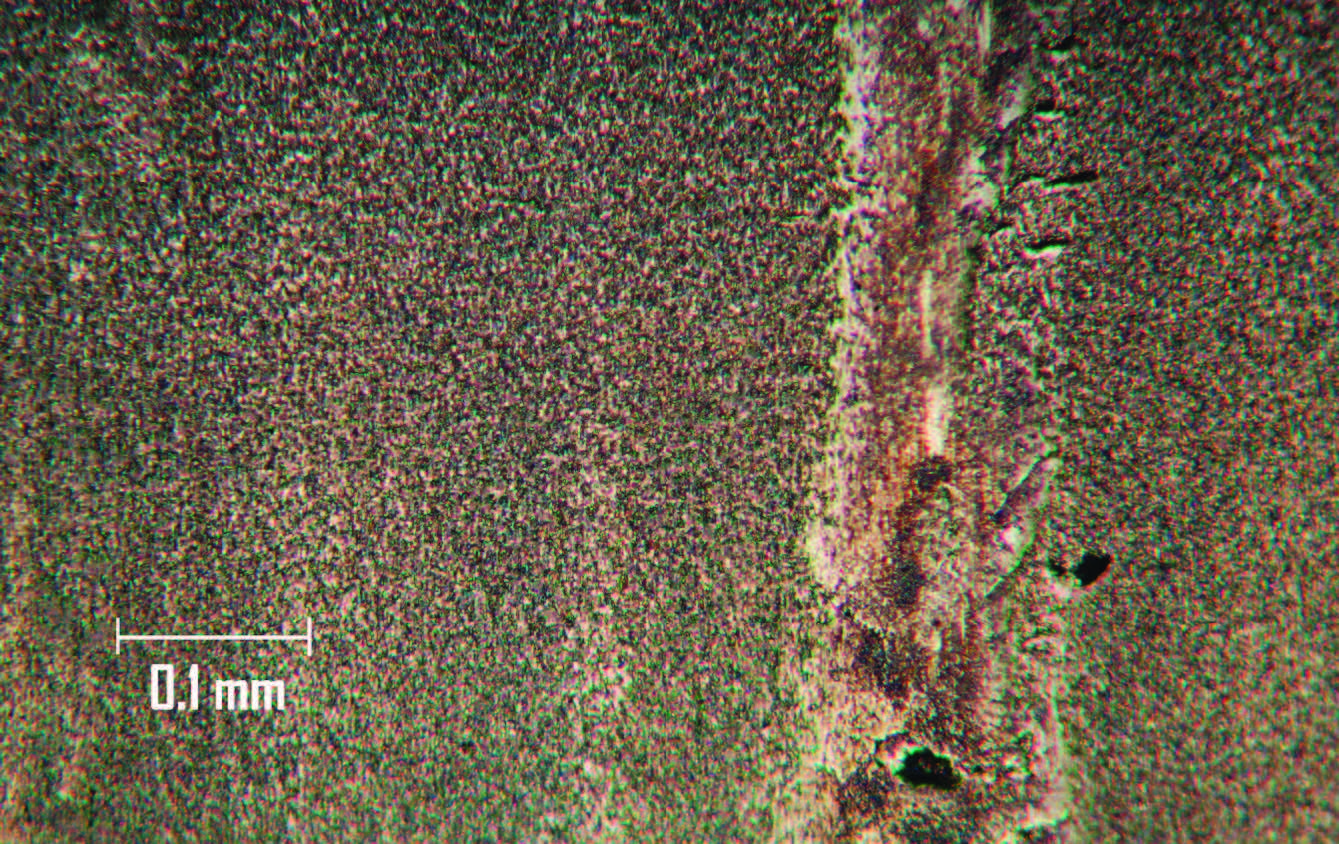
Figure 5. A lubricated steel surface operating in the mixed regime under a constant current of ~250mA and ~1V. Showing a mottled/frosting type appearance, there’s some evidence of tribofilms and some small surface pitting. Figure courtesy of Ingram Tribology.
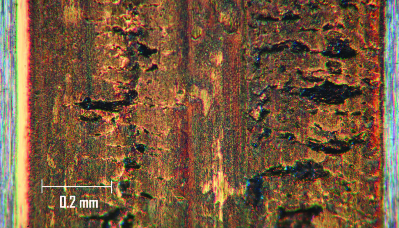
Figure 6. A lubricated steel contact in the mixed regime under a constant electrical current of ~250mA and ~1V. This is showing surface cracks and subsurface initiated pitting. WECs were later found under this surface. In the absence of any electrical current, this experiment would show no damage and no failure. Figure courtesy of Ingram Tribology.
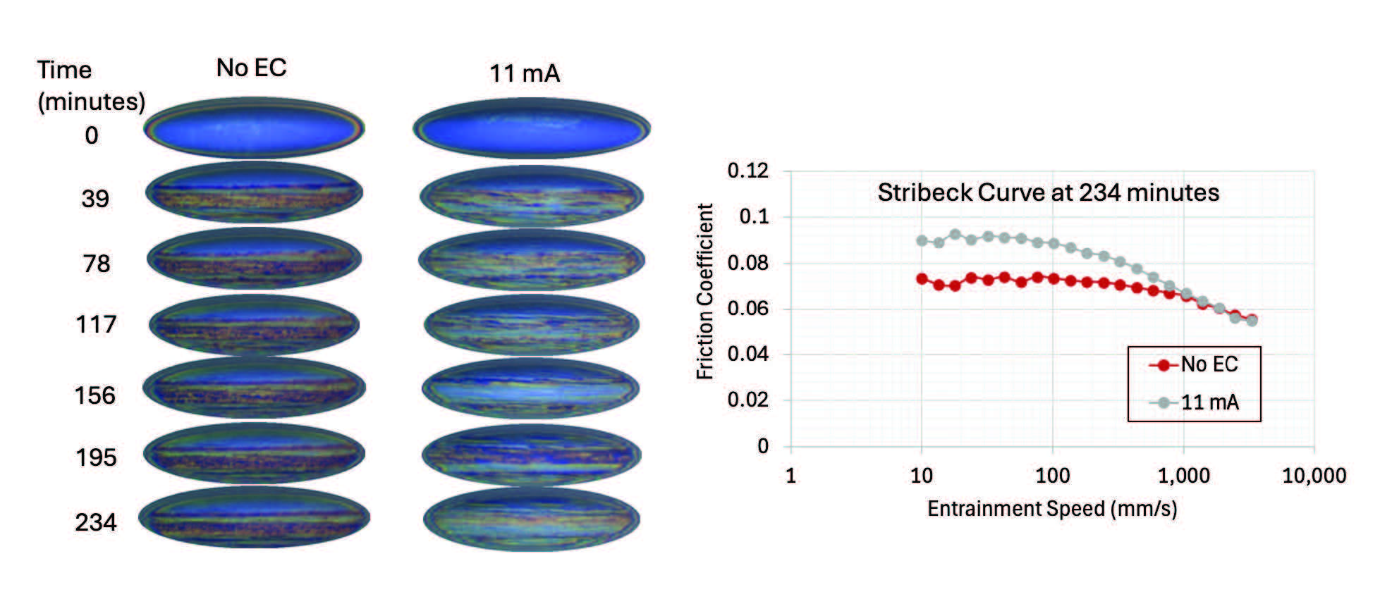
Figure 7. The progression of tribofilm formation on a steel surface, with and without the application of an electrical current. The addition of a 11 mA current during tribofilm formation can hinder its growth, leading to higher friction and likely less protection against wear. Figure courtesy of Ingram Tribology.
Notay concurs around ceramic bearings. “Insulated bearings, with a ceramic layer on the raceways, or hybrid bearings, with silicon nitride rolling elements, virtually eliminate all damaging currents. Hybrid bearings block electrical pathways from both high frequency EDM currents and low frequency circulating bearing currents (from common mode currents).
"However, they increase cost so are only used by premium OEMs in high end vehicles.”
“Shaft grounding rings (brushes) provide a high conductive pathway to lead the circulating and EDM currents away from the bearings. The problem for them could be wear, and this may become a maintenance item, but time will tell as more EVs are in operation,” says Notay.
Other hardware/software solutions are available, including shielded cables, electrical filtering, common mode chokes and sine wave filters.
Many have suggested that much of the solution could be achieved by the fluid. Per Ingram, “In terms of the more subtle effects—like how chemical additives behave in lower voltage/current contacts (~100mA)—this provides both a risk and an opportunity, as there is clearly a large effect of the current on additive reactivity. This could be utilized to help design new chemistries and formulations to enhance fluid performances and prevent known failures in contacts that are exposed to stray currents.”
Lee agrees. “There is certainly scope to refine the lubricant by removing some of the additives. There is little requirement for friction modifiers, for example.”
Formulators have the conundrum to face that thicker film thickness leads to greater breakdown voltage and therefore less chance for an arc to take place in a tribological contact. But in an EV, “a thicker oil film means higher viscosity, which reduces mechanical efficiency,” says Notay.
Many mention fluid conductivity as another lubricant property that could be changed. Notay has other thoughts on the impact of fluid conductivity and breakdown voltage. “While we can modify the conductivity of the fluid, can this meaningfully impact the breakdown voltage? No. In reality, the lubricant film in the contact is very thin. When you consider that typical breakdown voltages are in the order of 20-40V/µm and lubricant films are in the order of nm, you only have a few small volts to play with, and fluid conductivity plays little role in a formulating window, and we have proved this in our tests.”
Will these issues be addressed in future? Lee is not sure. “As EV development has slowed, it is doubtful whether some of these issues will now be addressed. There just are not sufficient failures to justify the huge investment. There is more interest in improving efficiency, which translates to greater range or smaller batteries.”
He’s even more blunt about mitigation. “If the shaft in an EDU was electrically grounded, EIBD wouldn’t apply.”
REFERENCES
1.
https://en.wikipedia.org/wiki/Electric_generator
2.
https://www.deutschlandmuseum.de/en/history/calendar/1881-05-16-the-first-electric-trams/
3.
https://grs-uk.org/publications_booklets/electric-locos-booklet-1/electric_locos_booklet_1.html
4.
https://search.abb.com/library/Download.aspx?DocumentID=9AKK106930A4001&LanguageCode=en&DocumentPartId=&Action=Launch
5.
Sosa, Y. (2025), “Vehicle fluids,” TLT,
81 (11), pp. 30-40. Available at
www.stle.org/files/TLTArchives/2025/11_November/Webinar.aspx.
6.
www.est-aegis.com/bearing-damage/shaft-voltage-and-bearing-currents
7. Zhao, J. (2023), “On wind turbine main shaft bearing currents,” Licentiate Thesis, Chalmers University of Technology,
https://research.chalmers.se/publication/539305/file/539305_Fulltext.pdf.
8.
Keller, J., Sheng, S., Guo, Y., Gould, B. and Greco, A. (2021), “Wind turbine drivetrain reliability and wind plant operations and maintenance research and development opportunities,” Golden, CO: National Renewable Energy Laboratory. NREL/TP-5000-80195,
https://nrel.gov/docs/fy21osti/80195.pdf.
9.
Mantione, L., Muzio, F., De Boni, G., Trombetta, M. and Frosini, L. (2025), “On the Shaft Voltage to Detect Faults in Wind Generators,” 2025 International Conference on Clean Electrical Power (ICCEP), Villasimius, Italy, pp. 269-276,
https://ieeexplore.ieee.org/document/11143629.
10.
Notay, R.S. (2025), “A brief review on the tribological effects of electrically induced bearing damage,”
J. Tribol., 147 (5).
11.
Janik, J., Saha, S., Jackson, R. and Mills, G. (2024), “Exploring the boundaries of electrically induced bearing damage in grease-lubricated rolling contacts,”
Lubricants, 12 (8), 268,
https://doi.org/10.3390/lubricants12080268.
12.
Lee, P.M., Sanchez, C. Moneer, M. and Velasquez, A. (2024), “Electrification of a Mini Traction Machine and Initial Results,”
Lubricants, 12 (10), 337,
www.mdpi.com/2075-4442/12/10/337.
STLE member Trevor Gauntlett is a freelance writer and consultant on lubricants based in Wirral, UK. You can contact him at trevor@gauntlettconsulting.co.uk.