KEY CONCEPTS
•
Additive manufacturing enables the creation of complex, lightweight and customized metal parts directly from digital designs, but typically requires post-processing to achieve final tolerances and surface finish.
•
An array of AM processes produce unique microstructures and surface qualities, which influence machining requirements and final part performance.
•
Friction effects during recoating and the choice of powder characteristics significantly impact surface roughness, dimensional accuracy and overall quality of AM metal parts.
Additive manufacturing (AM) for metals is the process of building parts layer-by-layer from metal feedstock (usually powder or wire) using a focused energy source or temporarily binds the powder with a polymeric binder phase. Metal AM technologies allow the fabrication of components without any geometric limitation. As such, advantages over conventional manufacturing technologies include the ability to create complex geometries, lightweight structures and one-off customized parts. AM also enables part consolidation (reducing a multi-piece assembly into one), rapid prototyping, waste reduction and design freedom.
Hoa Nguyen, product manager, Velo3D Inc., notes that, unlike casting or machining, AM creates near-net-shape components directly from 3D CAD data, enabling intricate geometries such as internal cooling channels or lattice structures that would be impractical to machine.
In practice, metal AM can produce high-density parts (typically ≥ 99%-99.5% dense) with mechanical properties comparable to wrought alloys after proper post-processing. Nguyen uses the example of a Ti-6Al-4V aerospace bracket printed by laser powder bed fusion that can achieve fine detail and a α′ martensitic microstructure requiring stress relief. (Ti-6Al-4V [often called “Titanium 6-4”] is the most widely used titanium alloy. Its name comes from its composition: 90% titanium, 6% aluminum and 4% vanadium by weight.)
AM does have drawbacks. Per Bibek Poudel, research engineer, GE Aerospace Research, “While AM is an attractive option for industries such as aerospace, automotive, biomedical and energy, several research efforts are being conducted to improve the scope of AM technologies to overcome its limitations such as lower range of materials, high cost, low productivity and significant need for post processing.”
Nguyen adds, “Practical reality is that support structures, thermal stresses and as-built surface roughness means parts usually undergo post-process steps such as heat treatment and finish machining to meet final tolerances and surface requirements. AM is thus best viewed as a complementary fabrication method that excels in making complex, custom or weight-optimized metal components, while still conforming to established quality standards for critical applications.”
AM techniques
There are several technologies available for the AM of metal parts including:
•
Binder jet printing (BJP). This involves depositing a liquid binder onto a powder bed to build parts that are later cured or sintered. It’s used most often for cost-effective metal parts, sand molds and complex shapes.
•
Material jetting. This involves jetting tiny droplets of photopolymer or wax that are cured by ultraviolet (UV) light. It produces smooth, detailed prototypes and full-color models.
•
Laser powder bed fusion (LPBF). This uses a laser or electron beam to fuse powdered material layer by layer. It is ideal for strong, complex metal and polymer parts in aerospace, medical and automotive.
•
Electron beam melting (EBM). This is similar to LPBF, but instead of a laser it uses a high-energy electron beam to selectively melt layers of metal powder inside a vacuum chamber.
•
Material extrusion (fused deposition modeling [FDM]/fused filament fabrication [FFF]). This involves feeding heated thermoplastic filament through a nozzle to create parts layer-by-layer. It is widely used for low-cost prototypes, tooling and functional parts. FDM is the original trademarked term coined by one of the first companies to commercialize the technology. Because it’s trademarked, others in the industry avoid using it. FFF is the open-source community’s name for the same process, created to describe it without infringing on the trademark.
•
Sheet lamination. This involves bonding and stacking sheets of material, then cutting them to shape. It is commonly used for cost-effective prototyping, tooling and laminated composite builds.
•
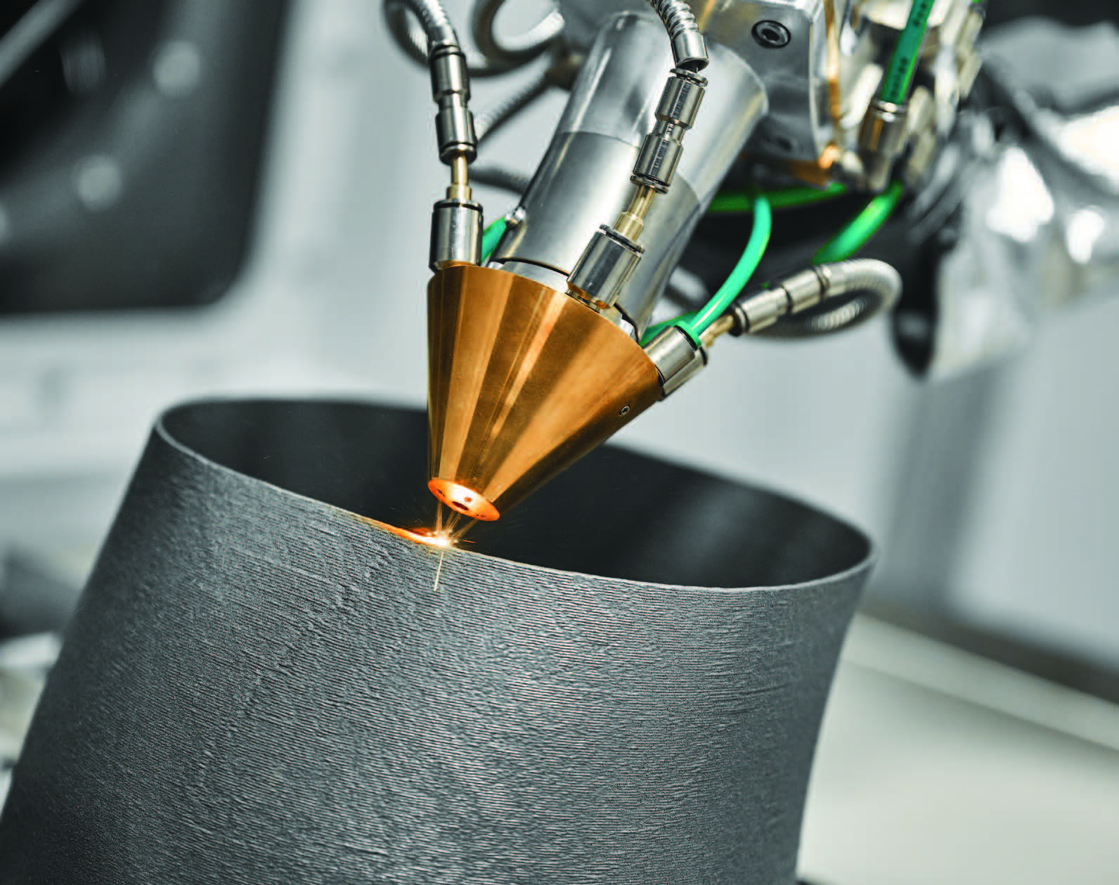
Directed energy deposition (DED). This involves depositing and melting metal powder or wire with a laser, electron beam or plasma arc. It is often used for repairing turbine blades and creating large structural parts.
•
Additive friction stir deposition (AFSD). This process uses a rotating tool to plastically deform and deposit solid-state metal feedstock without melting. It produces strong, defect-free parts in critical applications such as aerospace and defense.
Per Dr. Tony Schmitz, distinguished technical fellow, MSC Industrial Supply Co., powder bed fusion and DED have been more widely studied and implemented for initial AM industry applications—there is also significant interest in AFSD. Essentially, the deposition time and printing resolution inform the selection of the AM process.
Stainless steel, aluminum, nickel-based superalloys, titanium and cobalt-chrome are commonly used alloys.
Dr. Patrick Kwon, professor and chair, Department of Mechanical Engineering, San Diego State University, explains, “Some metals, such as titanium and aluminum, are prone to oxidation. Thus, such metal parts have to be produced with LPBF or EBM. Other metals such as nickel and ferrous alloys can be produced with BJP. Copper has been produced in EBM better than LPBF, I think, due to the reflection of the laser beam on copper powder.”
Nguyen adds that not all metal AM methods produce the same kind of part, and those differences carry through to machining and performance. He uses the following four examples.
•
In LPBF, a high-power laser fuses fine powder in 20-60 μm layers, resulting in parts with very high density (typically > 99.5%) and fine microstructures. For example, LPBF Ti-6Al-4V comes out with a martensitic α′ microstructure (needles ~1-5 μm thick) within prior-β grains ~50-100 μm; this makes the as-built material quite hard (e.g., ~36 HRC). Porosity in LPBF tends to arise from lack of fusion (if parameters are insufficient, causing irregular voids between scan tracks) or keyhole pores (if laser energy is excessive, trapping gas). Dimensional accuracy and feature resolution in LPBF are the best among these processes (small melt pool and powder = ~±0.1-0.2 mm tolerance on good machines). However, LPBF also induces high residual stresses due to rapid cooling—parts often require stress relief to avoid warping or cracking. From a machining standpoint, LPBF parts have a relatively rough surface (~10-15 μm Ra sidewalls as-built) with adhered particles, so finish machining needs to be planned. The material is equivalent to wrought in chemistry, but the microstructure (if left unannealed) can be harder on tools.
•
In EBM, powder is melted by an electron beam in a vacuum at elevated temperature. EBM parts (e.g., Ti-6Al-4V) solidify more slowly and at high chamber heat, yielding a lamellar α+β microstructure rather than martensite. This means as-built EBM Ti-6Al-4V is closer to an annealed structure (lower yield strength, more ductile), which can make it easier to machine once the abrasive surface layer is removed. EBM typically uses slightly larger powder (50-100 μm) and thicker layers (~50-90 μm), so surface finish is rougher (Ra ~20-40 μm is common) with a sandpaper feel. A unique aspect is that the surrounding powder is partially sintered to support the part during the build. So, an EBM part comes out encased in a sintered powder cake that must be grit blasted or cleaned off, leaving a matte surface with micro-notches where powder was attached. Porosity in EBM tends to be low overall (it can reach ~99.9% density), but lack of fusion can occur if beam parameters aren’t tuned. There are typically fewer gas pores since it’s under vacuum (no trapped gas in melt). Residual stresses in EBM are much lower—the preheated build (often 600°C-700°C for Ti) allows the part to stress-relieve in situ, so EBM parts usually don’t warp or crack, and sometimes can be used without post stress-relief heat treat. Accuracy of EBM is a bit coarser than LPBF (features might be ±0.2-0.5 mm, and small holes come out smaller due to the beam width). Machining EBM parts is often focused on removing the outer α-case (oxygen-rich surface from high-temp exposure) and any sintered debris. Once that’s off, the bulk material machines similarly to a casting or wrought material of the same alloy, but with large prior-β grain size that can cause anisotropic properties. For instance, EBM Ti-6Al-4V often has directional elongation differences but machines without the ultra-high tool wear of unannealed LPBF Ti, since it’s essentially pre-annealed by the process.
•
DED processes (such as laser blown-powder or Wire-Arc AM) produce parts by welding material onto a substrate. These parts typically have coarse columnar grains (often epitaxially growing layer-by-layer). The cooling rates are slower than PBF, so microstructures resemble castings or weldments, i.e., DED Inconel 718 will have large dendrites and perhaps Laves phases unless a subsequent heat treatment is done. Porosity in DED is usually from lack of fusion between passes or gas entrapment in the melt pool; densities around 98%-99% are common, and internal voids can be larger (like weld porosity). However, one advantage is that lack of fusion can often be mitigated by multi-axis motion to overlap beads. DED is relatively low resolution; typical as-deposited features might have ±0.5-1 mm tolerance or more, so substantial finish machining is expected. Surfaces are very rough; a wire-arc AM (WAAM) part can have a deposited surface roughness on the order of Ra 150-300 µm (visible weld ripples). Even powder DED (such as laser engineered net shaping [LENS]) yields ~50 µm Ra or higher. Thus, DED parts are often purposefully oversized and then 5-axis machined to final dimensions. DED builds, being essentially multi-layer welds, can accumulate significant residual stress, potentially leading to distortion or cracking in large parts, if not managed. Often, inter-pass cooling or intermediate stress-relief heat treatments are used for big DED builds. Machining DED parts is similar to machining a casting/weld structure—the material may cut easier if it’s in a softer, large-grained state, but a significant amount of material must be removed. Tools might see variable hardness if the part has segregated microstructures (e.g., harder carbides in some layers). Also, any oxide scale on bead surfaces should be removed (sometimes an initial grinding or milling pass is done just to get under the scale). Tool wear is usually manageable once past the outer scale; standard practices for machining cast or wrought alloy apply. One caveat, if the DED part wasn’t hot isostatic pressed (HIP) and has internal porosity, pockets can be exposed during machining which can affect surface finish or tool engagement (chip flow interruption).
•
BJP (with sintering) produces a very different kind of metal part. Here, a powder (often very fine, 5-30 µm) is glued then sintered, much like metal injection molding (MIM). The as-sintered microstructure is typically equiaxed grains with some residual porosity (i.e., ~95%-98% density is common unless HIP is applied). For example, BJP 17-4 PH stainless might show a homogeneous tempered martensite microstructure but with 2%-5% porosity remaining as small voids between particles. Surface finish of BJP parts is relatively good out of the furnace—Ra ~6-10 µm is typical for metal BJP after sintering because the powder is fine and there are no partial melt particles stuck on the surface (the sintering necks smooth out some roughness). However, there is often some dimensional shrinkage (~15%-20%) during sintering, and with that can come shape distortion. Tolerances for BJP are moderate—perhaps ±0.3 mm on a small part, but for larger parts one must account for shrink variation (designers often scale the initial model and use supports called “setters” during sintering). Since BJP parts are sintered in a furnace uniformly, they cool slowly—practically no residual stress remains (they’re essentially stress-relieved by the furnace cooling). Machining BJP parts can be akin to machining a (powder metallurgy (PM) part. If the part was not infiltrated or hot isostatic pressed, the residual porosity has to be considered, which can make the material slightly more abrasive (edges of pores can wear the tool) and can cause tool chatter if the part isn’t fully dense (less stiffness). Generally, though, BJP parts are machined with similar parameters as their wrought counterparts, perhaps with a slight reduction in feed to account for lower ductility. One also must be careful when clamping, since sintered parts can be a bit more brittle (until hot isostatic pressed). Often, critical features of BJP parts (such as threads or seal faces) are machined after sintering to meet tight tolerances and surface finish needs. The tool wear in those operations is usually not extreme—perhaps comparable to machining a casting of the same alloy—because the microstructure is uniform and relatively soft. For example, BJP 316L has yield strength much lower than wrought due to porosity, making it easy to cut, albeit at some cost to tool life from abrasiveness of pores.
 As far as tool wear during all of these processes, Schmitz observes, “Machining is ultimately a competition between the tool and workpiece materials. The tool wears at a rate which depends on these materials and the machining parameters. The same is true when the workpiece is additively manufactured.”
Friction issues that affect the AM printing process
As far as tool wear during all of these processes, Schmitz observes, “Machining is ultimately a competition between the tool and workpiece materials. The tool wears at a rate which depends on these materials and the machining parameters. The same is true when the workpiece is additively manufactured.”
Friction issues that affect the AM printing process
Nguyen explains the potential consequences of friction in AM processes—how they arise, why they matter and the ways they contribute to surface defects. The following examples highlight some of the most common friction-related problems and their impact on part quality.
•
Recoater bed interactions. A recoater is the component in powder bed–based AM processes that spreads a thin, even layer of powder across the build platform before each layer is fused. In powder bed fusion processes, friction between the recoater and the powder/part can introduce various defects. One common scenario is when the recoating blade (which spreads each new powder layer) contacts the partially built part due to an upstanding feature or warp—this can produce a telltale “witness mark” or streak in the powder layer. That streak indicates that the blade scraped the surface. It often results in a visible line or groove on the part’s side wall after sintering/melting the next layers. In severe cases, the recoater can crash (a hard frictional collision), shifting the powder bed or even knocking the part askew, causing layer misalignment or a build failure. Even minor blade-part friction, however, can shear off delicate features or supports; for example, a thin wall that curls up 0.3 mm from residual stress might get shaved by the blade, leaving a ragged edge or causing that layer to be under-filled with powder. These issues matter most in processes like LPBF or EBM where a recoater spreads powder every layer. Engineers need to factor friction into designs, for example avoiding tall, thin fins that might bend upward into the recoater’s path.
•
Powder bed shear. Another friction-related phenomenon is powder bed shear and disturbance. As the blade (or roller) moves across, it exerts shear force on the powder. If part of the previous layer wasn’t flat (i.e., powder clumped or a bit of spatter landed), the blade can drag that along, creating a streak of uneven powder. This shows up as lines of incomplete fusion or surface roughness on the part because some areas received a thinner powder layer after the streak (leading to lack of fusion in those spots). Essentially, friction can cause non-uniform layer thickness. A defective or worn recoater blade exacerbates this—a gouge in a metal blade will leave a recurring line of less powder, imprinted on each layer (producing a surface groove or even a crack line in the final part).
•
Spatter. This refers to tiny ejections of molten metal from the melt pool, propelled by recoil or gas pressure. Those spatter particles can land elsewhere on the powder bed, and when the recoater arrives, it can hit these semi-fused metal pellets like a bump. This can either push them, causing a streak, or get the blade to hop slightly, resulting in a local uneven layer. In the part, that might manifest as a small surface inclusion or a rough protrusion where the spatter particle was partially remelted.
•
Balling. This refers to a continuous melt track that breaks into droplets; often due to inadequate wetting or travel speed that is too high. These small metal balls solidify on the layer instead of a smooth track. When the recoater passes, it experiences friction trying to flatten these balls. Often the blade will flick some of them out or over, causing pits or extra powder mounds. On the part, balling leads to a rough, beaded surface texture and potentially lack-of-fusion voids under those beads. It is especially important for downfacing surfaces and low-angle overhangs where balling (dross) is more prevalent. Operators often see an increase in downskin (the downward-facing area) roughness due to this phenomenon. If balling is severe, the blade might even jam or ride up over a string of balled-up material, depositing excess powder in that region and causing a local layer geometry error.
Nguyen emphasizes that frictional interactions during recoating are critical to part quality. They can result in surface defects (streaks, grooves, raised rough lines) and internal flaws if layers aren’t evenly recoated. These issues are most pronounced in PBF processes when:
1.
a part warps or has features above the nominal layer height,
2.
excessive spatter or debris is present or
3.
the recoater itself has damage or is mis-set.
Best practices to mitigate these friction-related defects include using soft recoater blades or brush recoaters, which will deflect rather than scrape if they hit something; designing adequate supports and orienting parts to minimize steep overhangs (reducing risk of super-elevations contacting the blade); and ensuring the powder is dry and free-flowing, wet or clumpy powder increases blade drag.
“Ultimately, when recoater friction does occur, it shows up in the printed part as anomalous surface features, often requiring additional rework (grinding of a blade gouge line, etc.) or causing the build to fail outright,” Nguyen says. “Recognizing these signs during in situ monitoring (a sudden deep, guttural growl or a streak on layer images) is now a part of quality control in metal AM.”
However, when it comes to AM, not all friction is bad. Schmitz explains that in the case of AFSD (a solid-state process where wrought bar stock is severely plastically deformed to print metal parts layer-by-layer), frictional heating softens the bar stock sufficiently to enable it to be deposited without melting.
Hybrid manufacturing (additive and subtractive)
Hybrid manufacturing generally means additive and subtractive processes are integrated into a single machine tool. This integration reduces handling, ensures higher precision and enables complex designs that combine near-net-shape AM with high-accuracy machining.
“AM offers design flexibility and new opportunities,” Schmitz explains. “But it is often combined with machining to meet design requirements for surface finish and geometric accuracy of the final part. Hybrid manufacturing combines the capabilities of both AM and machining to produce parts that could not have been made otherwise. When machining additively manufactured preforms (intermediate shapes or structures that are created first and then further processed), a key consideration is the part stiffness. This is because the machining force required to remove material acts on the part. If the part is too flexible, conservative machining parameters must be selected and the machining time is increased. The associated machining cost can overwhelm the cost saving intended by minimum material use in the additive process. The design of preforms, therefore, should consider the printed part stiffness to enable machining after printing. A cost-based optimization of the preform design is a good strategy, where the costs associated with both AM and machining are considered.”
Schmitz emphasizes that the stiffness of the preform should be considered since it affects subsequent machining processes. “The location of the desired part within the additively manufactured preform must be known when programming the machining toolpaths in hybrid manufacturing,” he says. “The use of appropriate metrology, such as structured light scanning, to measure the preform can assist. Importing the part scan with fiducials that identify its coordinate system into the CAM software provides a method to ensure the desired part geometry is obtained after machining.”
The alloy composition can affect the machining process for hybrid manufacturing processes. For example, some alloys are more prone to adhesion to the tool surface, which can affect the surface finish. Selection of appropriate machining parameters and coolant strategies can achieve the optimal surface finish.
Best practices for improving production of AM metal parts
According to Poudel, the best ways to improve productivity while machining AM parts are to:
•
Optimize tooling. Since AM parts are a bit rougher, high-performance coating or use of lubricating agents in the milling tool improves the machining performance. Similarly, as there are inherent issues with AM such as high porosity and high residual stress, an assessment of stress concentration zone and avoiding concentrated load in those areas during machining will help with smoother operation.
•
Optimize cutting parameters and the toolpath to accommodate complicated AM-fabricated geometries.
•
Minimize additional post processing. Per customer requirements, if further post-processing can be avoided in the AM part, that would reduce a significant amount of time for final part production.
The surface finish during the milling/machining of additive manufactured parts
Kwon says that if the AM parts are fully densified and hot isostatic pressed, he would expect the surface finish to be as good as a traditionally manufactured part, with the following caveats: Because most AM parts are made by LPBF systems, the parts would have some process-induced residual stresses. In that case, it may not affect the surface finish, but could impact the tolerance of an AM part. Other factors that may affect the surface finish are defects such as voids and inclusions that make the requirement of a fully dense and pristine chamber environment necessary. For example, a small amount of oxygen can yield oxide particles by reacting with the metal powder. As such materials are being cut, they will impact the surface finish as well as increase tool wear.
Nguyen notes that as-built metal AM surfaces are significantly rougher than conventional machined surfaces, so finish machining is almost always required. Side walls (vertical surfaces) from LPBF typically have Ra ~8-20 μm average roughness, with a matte, sand-cast appearance caused by the “stairstep” layering and partially fused powder particles on the surface. When end-milling these surfaces, the initial passes produce intermittent cutting as the tool knocks off high spots (i.e., semi-sintered particles sticking out).
In contrast, upskin (upward-facing) surfaces (such as the top of a build) tend to be smoother, often ~5-10 μm Ra, because the melt pool solidifies against solid underlying material. Downskin surfaces (overhangs that were supported only by loose powder or minimal supports) are usually the most challenging; they often exhibit a scaly “dross” texture with Ra well over 20 μm due to gravity-induced sagging of unsupported melt metal. Nguyen uses the example of a downfacing 30-degree overhang on an Inconel 718 LPBF part that might have rough, partially fused droplets adhering underneath, which leave behind pockmarks or weld-like beads after the first machining cut. (Inconel is the trade name for a family of nickel-chromium-based superalloys known for their ability to withstand extreme heat, pressure, and corrosion.) Surfaces that had support contacts will have even more irregular scars or stub remnants once supports are removed. After an HIP treatment, the internal pores are collapsed (improving subsurface density) but the exterior roughness does not vanish—in fact, HIP can form a slight oxide scale that needs cleaning off. Therefore, machining AM parts usually involves removing a defined allowance (often ~0.5-1 mm) of material to get to good metal. Once that outer crust is milled away and any scale/support scars are gone, the machined surface finish can be brought to typical values (e.g., Ra <1.6 μm) like any other machined part. Notably, the machinist will observe that tool engagement is initially uneven (due to the rough as-built profile), but after the first semi-finish pass the surface starts to behave like a homogeneous material, revealing a shiny finish comparable to machining a casting after cleanup.
Poudel sees one of the biggest challenges of AM technology as its poor surface finishing because of a staircasing effect. “Also, the unbonded or partially bonded powder particles cause an uneven surface on the AM part,” he explains. “Hence, a lot of effort is being made to address this challenge—one of them being milling of the AM parts after they are fabricated. A milled AM part has a fine, machined texture with visible tool marks and patterns from the cutting process. These marks can further be reduced with polishing or other surface finishing techniques.”
Poudel adds, “The dimensional accuracy and smoothness of the surface improves significantly after milling as compared to the as-printed AM part. Milling removes the burrs and uneven surfaces created from partially melted metal powders. The build lines are also removed after milling. As per surface roughness, it varies depending on the material, cutting parameter and milling tool. For example, the as-printed SLM stainless steel part ranges from 10-20 microns of Ra whereas after milling it drops down to around 1-4 microns depending on the cutting parameter and cutting tool.”
How the metal powder type affects surface finishes
Kwon observes that the surface finish of the AM part depends on processing conditions but is largely impacted by the powder size. EBM, which limits the size of the powder due to the electron charge, typically uses much larger powders than more popular LPBF systems. Thus, the surface of EBM parts is much rougher when compared with LPBF parts.
Poudel cites the following four aspects of powers that determine the final surface finish.
•
Particle size. Smaller particles result in smoother final surface than larger particles due to thinner layers.
•
Particle shape. Spherical particles flow better and pack uniformly resulting in surfaces smoother than irregular-sized particles.
•
Material properties. Since different materials and alloys have different thermal properties (varying melting points, conductivity and solidification behavior), surface roughness changes according to material. For example, titanium produces a smoother surface than nickel-superalloys.
•
Powder quality. Any contamination in the feedstock powder causes oxidation and other defects resulting in poor surface quality.
Nguyen mentions powder reuse as another consideration. With repeated reuse cycles, powder can pick up moisture or oxygen and accumulate ultra-fines. This can slightly degrade surface quality over time; studies on Ti-6Al-4V have shown that reused powder (with more oxide) can increase roughness and porosity in the parts. However, if powder is properly sieved and conditioned, many users report minimal change in surface finish over multiple reuses.
The contribution of tribology to AM
Nguyen believes that tribologists can contribute to AM in four niche but important ways.
1.
During the AM machine operation, tribologists might help improve or select recoater blade materials/coatings that minimize sticking or abrasion by powder thus reducing streak defects.
2.
They might also analyze the wear of machine components (such as nozzle liners in DED or guide rails in powder beds) to improve maintenance schedules and longevity—these machines deal with powders (which are abrasive) and high-temperature moving parts, a classic tribology challenge.
3.
Regarding part usage, tribology comes into play because AM allows design of novel surface textures or lubrication channels. Tribologists can advise on post-process surface finishing or coatings for AM parts that will be in sliding contact or rolling contact.
4.
Tribologists can also leverage AM for surface texturing; printing micro-dimples or special patterns to retain lubricant. Tribology expertise can guide such designs to enhance performance.
“Finally, I’d add that those sourcing AM parts should consider qualification of the design itself: does the part take advantage of AM’s strengths (or at least account for its differences)?” Nguyen concludes. “If a part has critical surfaces involved in tribological performance (low friction, low wear), tribologists should be brought in to assess if the as-printed surface or proposed post-processing will meet those needs. Likewise, tribologists can help in selecting lubricants compatible with any surface porosity or roughness left on the part. Tribology considerations should be taken into account in the AM process (to mitigate machine wear and process friction issues) and in the part’s final application (to tailor surfaces and finishes for optimal performance). The intersection of AM and tribology is fertile ground: from designing self-lubricating lattice bearings to understanding powder flow in recoaters, a lubrication engineer’s insight can drive better outcomes in AM projects.”