Meet the Presenter
This article is based on a webinar titled Vehicle Fluids: New Tribology Challenges hosted by the American Society of Mechanical Engineers’ (ASME) Tribology Division and presented by Dr. Peter Lee on April 10, 2024. Courtesy of STLE, this article captures the core insights from this ASME-organized event. For more technical content from the ASME Tribology Division Webinar Series, visit the ASME Tribology Division’s website at www.asme.org/get-involved/groups-sections-and-technical-divisions/technical-divisions/technical-divisions-community-pages/tribology-division.
Dr. Peter Lee is an institute engineer and chief tribologist for the Tribology Research and Evaluations Laboratory at Southwest Research Institute and was responsible for establishing the world-class tribology research laboratories, developing new test techniques and helping clients find answers to their questions. As part of this research, he holds 10 patents, with five pending, has over 35 peer-reviewed papers and has given over 120 presentations internationally.
Lee began his career as a qualified motor vehicle technician (light and heavy duty) before attending the University of Leeds, UK, where he earned a degree in automotive engineering in 2002 followed by his doctorate in 2006 in engine tribology, developing techniques for the extraction and tribological testing of lubricants from various parts of the engine, including the piston assembly. In 2007 he was successful in his application for a Royal Academy of Engineering Research Fellowship. Through this five-year program, he continued research into engine tribology, as well as supervised undergraduate and doctoral students and lectured tribology to undergraduate and graduate students. In 2010 he accepted the invited position of principal engineer – tribologist at Southwest Research Institute and in 2011 moved with his family from York, UK, to San Antonio, Texas.
Lee has served as a TLT technical editor, is an associate editor for Tribology Transactions and is on the editorial board for the journal Wear. He was instrumental in establishing the STLE Tribology & Lubrication for E-Mobility Conference and has been on the STLE E-Mobility Conference Planning Committee since its inception in 2021. He is also an STLE Fellow, IMechE Fellow and UK Chartered Engineer. He is currently STLE Treasurer.
You can reach Lee at peter.lee@swri.org.

Dr. Peter Lee
KEY CONCEPTS
•
Electric vehicle fluid testing is an emerging research area, with standardization coming.
•
Commercial test rigs are now available, with more in development.
•
Application of DC or AC current increases wear over non-electrified tests, changes friction response and changes fluid and grease properties.
•
More work is needed to define test parameters and understand why electrification changes the response of tribosystems.
The objective of this article is to discuss new challenges for vehicle fluids. Specific topics of discussion are the following:
•
Internal combustion engine (ICE) vehicle fluid challenges
•
Electric vehicle (EV) fluid challenges
•
Effect of stray currents in electric drive units
•
Explore currently available commercial eTribology and eRheology test rigs
•
Rigs and collaborations (almost certainly not all encompassing)
•
National labs, universities and research institutes
•
Not covering industrial labs
•
More in-depth results
This article is based on a webinar presented by STLE Fellow Dr. Peter M. Lee, an institute engineer and the chief tribologist at Southwest Research Institute (SwRI), to the Tribology Division of the American Society of Mechanical Engineers (ASME) titled Vehicle Fluids: New Tribology Challenges. See Meet the Presenter for more information.
Dr. Lee states that there are real challenges within ICEs as they continue to develop architecture for improved efficiency. The very thin viscosities, such as 0W-16 oil, and emissions compatibility concerns with after-treatment systems are causing issues. Researchers are now looking at different fuels such as ammonia and hydrogen and their effects on lubricants—both with operating in the combustion chamber, and how it affects the lubrication and engine performance, across various types of powertrains, including hybrid vehicles.
There are many different types of vehicles all with different tribological challenges. Here are some of the vehicle fluid challenges:
• ICE
•
Continue to develop architectures and additive and coating technologies for improved efficiency
•
Running on 0W-16 and 0W-08
•
Continued emissions pressure and aftertreatments
•
Different fuels – ammonia, natural gas, hydrogen etc.
• Hybrid vehicles
•
Emulsion build-up
•
Lubricant changes due to emulsion, even when “burnt” off
• EVs
•
Compatibility with copper and coatings
•
Aeration, high speeds
•
Stray currents
•
Cooling
Vehicle fluid research
Dr. Lee states that research work is being undertaken to study effects of electrification on lubricants and resulting friction, wear and film thickness. In general, EV fluids is a rather new industry with testing capabilities catching up. It is typical for the industry to have lubricants arrive first, and then a need for standardization abilities to test that the lubricants work correctly follow afterward.
Overall:
•
New industry with testing capabilities catching up
•
ASTM working to bring in standards
•
OEMs working on draft lubricant specifications
•
New research areas
Dr. Lee says: “The previous paragraph here opens up new research areas, thus the presentation’s focus from this point forward is the research work that’s going on to understand the effects of electrification on the lubricants and resulting friction, wear and film thicknesses that are occurring there.”
What are some of the key components that drive EVs?
•
Three-phase AC motors (permanent magnet or induction) currently provide primary traction for all major battery electric vehicles (BEV).
•
In the case of BEVs, the battery pack supplies DC voltage to a high-frequency switching inverter, which then converts DC to AC for powering the traction motor(s).
•
Effects of induced shaft voltages and high voltage electric fields on friction and wear properties are not well understood.
Figure 1 shows that there is a common mode voltage. Lee explains: “On the top, the diagram shows a sine wave but a very rough sine wave—so inverters aim to change the DC to AC by changing the sine wave very quickly to actually get the motor to run, but this omits discharge that takes place, and that often goes through the shafts, and therefore ends up going through the bearings. Thus, the problems begin.”
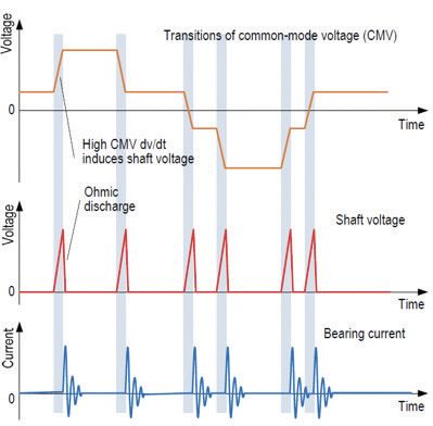
Figure 1. Transitions of common mode voltage (CMV). Figure courtesy of Southwest Research Institute.
Figure 2 shows the ideal voltage. Overall:
•
Common mode voltage (CMV): Voltage between the three-phase neutral and ground.
•
Inverters mimic a sine wave by switching voltage on and on off very quickly, generating non-zero CMV.
•
The rapid change in voltage over a very short period can generate currents often grounded through the bearing.
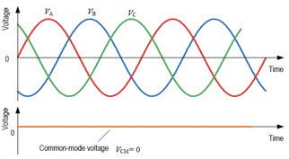 Figure 2. Ideal voltage. Figure courtesy of Southwest Research Institute.
Shaft voltage sources: historic causes
Dr. Lee explains: “When we think about electrostatic and magnetic effects, there are historic causes that have always been out there, particularly in things like wind turbines, e.g., white edge cracking, which can help us understand what is happening in electric vehicles’ systems.”
Electrostatic effects
•
Static friction inside the machine generates a potential between the rotating and stationary component.
•
High enough charge build-up could exceed breakdown voltage of thin film lubricant.
Magnetic asymmetry
•
Originates from manufacturing defects or imbalanced voltage supplied by inverter.
•
Generates low frequency, circulating currents.
Areas for tribological study
When it comes to areas for tribological study, Dr. Lee explains: “There are common rotating parts inside the EV, such as shaft bearings, electric motor bearings, transmission case bearings and wheel bearings; then there’s also gears, the seals that aren’t rotating, but the shafts are that are operating in the seals. There are also slip ring brushes and other electric floating components that are going to be affected.”
• Common rotating parts inside of an EV:
•
Bearings
• Electric motor bearings
•
Transmission case bearings
•
Wheel bearings
•
Gears
•
Slip ring brushes
Proximity to high voltage electric motors enhance risk of shaft voltage effects and/or electric field effects
Commercially available rigs
There are a limited number of commercially available rigs at this time, with more currently being developed. To date there is a bearing test rig that uses a deep groove ball bearing, a mini traction machine (MTM) and a company offering a rig with electrified modules, including block-on-ring, four-ball, reciprocating, fretting and pin-on-disc. There is also a company offering an electrified rheometer.
Dr. Lee adds: “Most of the work being done has been in non-industrial situations. There are some industrial companies that have bearing testers that they’ve electrified, but as far as in the research field, national labs as mentioned have been looking at micro cracking in electrified micro pitting test rigs.” There is also an increasing number of non-industrial research labs and universities with adapted rigs as e-testers.
Electrification of block-on-ring
Dr. Lee’s team electrified a block-on-ring
(see Figures 3 and 4), which was the very first one that was started a couple of years ago. Dr. Lee states, “The reason why we selected the block-on-ring was it’s a line contact which allowed us very quickly and easily start to understand if there was even an effect and whether there was anything worth investigating.”
• Start with block-on-ring architecture
•
Relevant test geometry for high-speed bearings
•
Familiar test concept with standard parts available
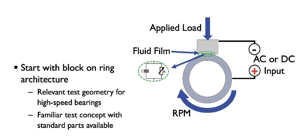
Figure 3. Electrification of block-on-ring. Figure courtesy of Southwest Research Institute.
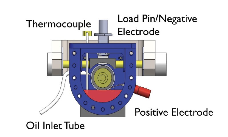
Figure 4. Block-on-ring. Figure courtesy of Southwest Research Institute.
Oil heating
Dr. Lee says: “One of the things we were cognitive of from the very beginning, due to earlier mentioned magnetic effects, frictional effect, etc., is we wanted to take heating of the oil effects away from the tribological contact, to make sure that everything that was happening in the process of heating and pumping oil was not affecting the results. We conducted the following experiment:
•
Heated oil setup separate from module due to need to remove effect of heater coil from EV environment.
•
Heat exchanger allows for hot oil without disturbing peristaltic pump.
•
System is temperature measured and controlled direct through test rig software at point of delivery.”
Electrical systems
Dr. Lee continues: “One of the hardest things to do when setting it all up is to be cognitive to isolate the block-on-ring components from the test machine.” Below is what was used for the DC power source and AC power source.
• DC power source
•
60V, 10A adjustable switching power supply
• AC power source
•
Switch mode amplifier
Systems were chosen based on experience with other programs at SwRI:
•
EV fluid durability testing on EV
•
EV fluid aeration study on electric drive units
•
Extensive battery lab studies
Table 1 shows multiple variables that were studied of three different lubricants. Dr. Lee says: “We notice the biggest difference with the variable speed test sequence.”
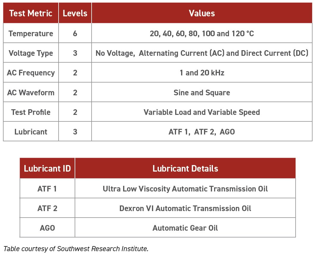
Table 1. Variables of interest. Table courtesy of Southwest Research Institute.
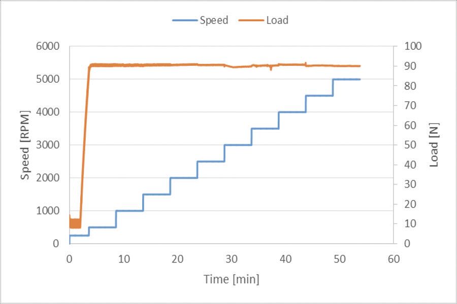
Figure 5. Final test sequence – variable speed. Figure courtesy of Southwest Research Institute.
“Figure 5 shows the final test sequence that was settled on which gave the best response—very short running,” Lee explains.
• Load
•
10 N start
•
Constant 90 N
• Speed
•
250 rpm, 2 min
•
500 to 5,000 rpm
• Time
•
52 min
• 30 V, 2A DC
• 2A, 10kHz AC
Dr. Lee continues “Figure 6 shows two test runs; the left hand, the one above the other, shows the same run, just repeated. The same with the right-hand side. The product that was tested is ATF 1 (automatic transmission fluid), which was the low viscosity oil. There is a difference between AC and DC, and there is more wear with DC.”
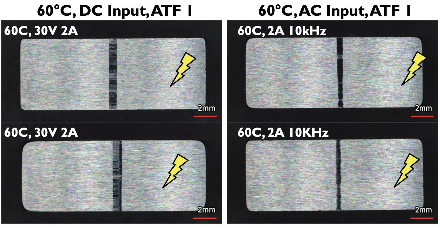 Figure 6. Wear results. Figure courtesy of Southwest Research Institute.
Dr. Lee says: “We did three measurements, ends and middle of the wear scar, and we only called it valid if we had a coefficient variance of less than 10% as per ASTM standards.”
Lee says: “Figure 7 shows friction response for block-on-ring testing. In all cases, the coefficient of friction (CoF) approached the same steady value, 0.14. Gradual with no current, quicker with DC; thus, there is a current affect on the lubricant that effects friction.”
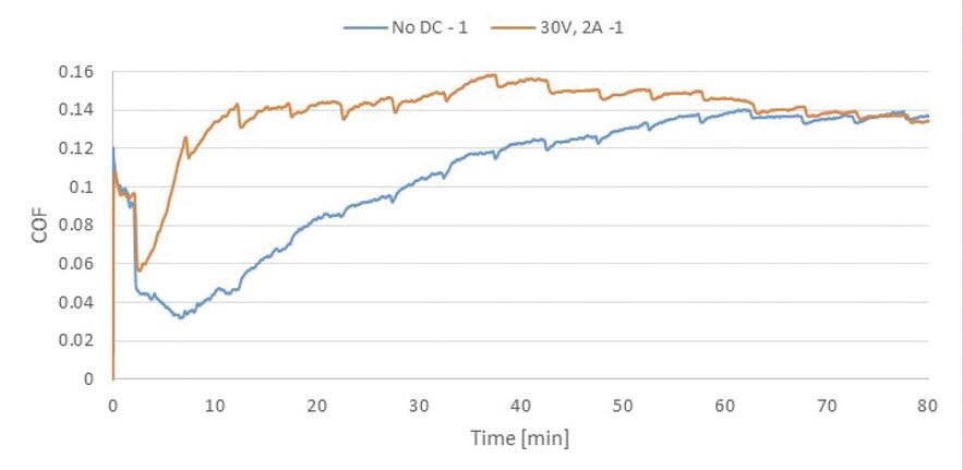
Figure 7. Friction results. Coefficient of friction (CoF) comparison at 25°C – DC input. Figure courtesy of Southwest Research Institute.
After finding notable differences in wear on the blocks between non-electrification and AC and DC electrification, Dr. Lee’s team proceeded in electrifying an MTM with the help of the manufacturer. Three runs were conducted. Figure 8a shows results with ULV ATF tests without AC or DC power. Good repeatability between the three runs was evident. Figure 8b shows results when either AC or DC current is added. The results show that AC or DC current affect the results, increasing traction and reducing repeatability.
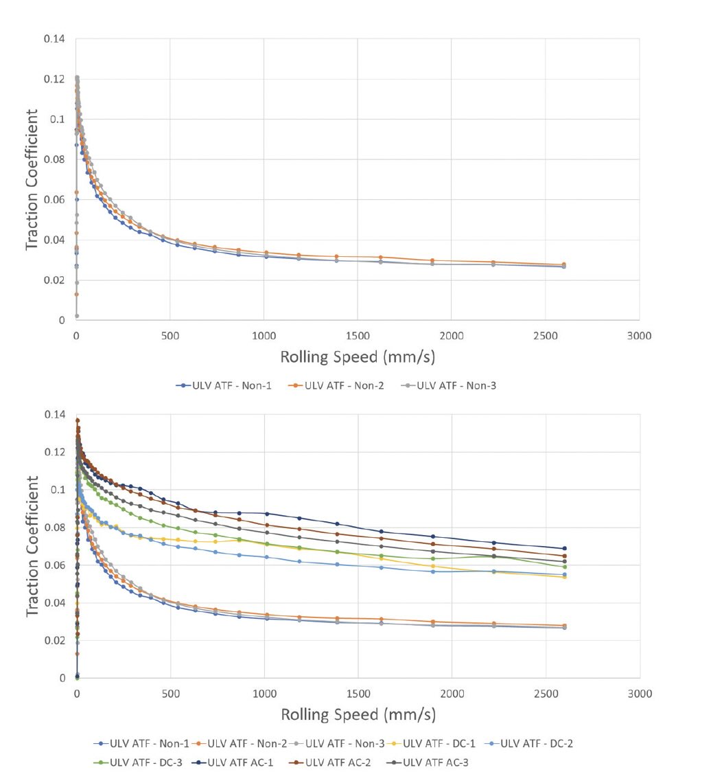 Figure 8. ULV ATF 100°C. a.) No AC and DC. b.) +AC + DC. Figure courtesy of Southwest Research Institute.
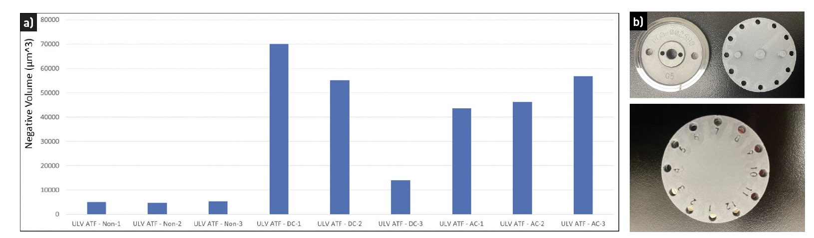 Figure 9. Test results. Figure courtesy of Southwest Research Institute.
Figure 9a shows test results, and Figure 9b shows that there were 12 locations where wear was analyzed, which gave an average wear as well as whether the wear was consistent around the disc. Tests results were concluded as follows:
• Nomenclature
•
DEXRON VI ATF – Non-3 = {oil} – {electrification}-{run#}
• End of test wear analysis
•
White light interferometer
•
12 equally spaced areas around the wear track
•
Average volumetric wear of measurements (µm3)
•
White light images of wear
Figure 9a shows all results. First three columns show no electrification, the next three show results with DC added and the final three with AC added. Repeatability is poor with AC and DC added, and wear is significantly higher than with no current added.
In addition, wear scars
(see Figure 10) were reviewed and the results are similar. Non-electrified results are much better; the electrified version results in wear and pitting, and other evidence shows that presence of electrification can cause more surface oxidation.
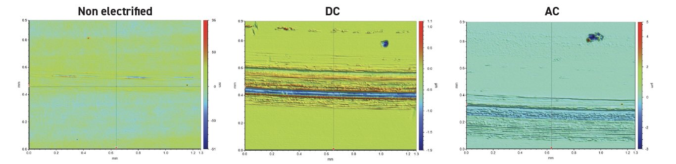
Figure 10. ULV ATF wear results. Figure courtesy of Southwest Research Institute.
Additional considerations: Many additives in lubricants are polar molecules. Dr. Lee states: “If they are polar molecules, the question is, is the electrical current having an effect upon them? And is this why we see more affect under DC than we see under AC? Because the DC is able to align them and not confuse them, whereas under the AC they are rather bouncing backward and forward. There is also some evidence that the presence of electrification can cause more surface oxidation, and so that can affect what is happening here.”
He continues, “STLE Past President Dr. Ali Erdemir and Dr. Leonardo Farfan-Cabrera have been exploring the oxidation rates across different tribological contacts. Their test results suggest that passing DC current increases CoF and wear of dry sliding contacts while it slightly reduces CoF but increases wear significantly for lubricated contacts due to accelerated oxidation by electrification.”
Other learning is that if the test is not set up properly, there is high chance of damage occurring. For example, large pits in the wear scar due to electrical discharges may occur. Figure 11 shows pitting results.
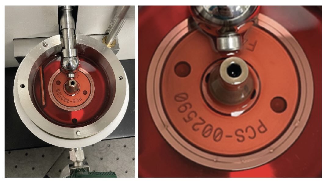
Figure 11. Pitting results due to electrical discharges. Figure courtesy of Southwest Research Institute.
Effect of electrification of rheological behaviors
Electro-rheology testers are built around the MCR series rheometers
•
Many configurations available
•
Support from the manufacturer
•
Offer same rheological analysis for EV fluids as currently offered for ICE drivetrain fluids
Dr. Lee says: “The electrification has an effect on the rheological behavior. So it isn’t just the viscosity, but some other things also change.”
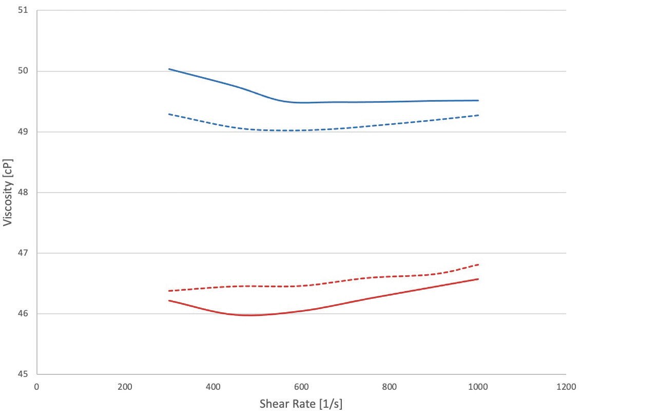
Figure 12. Electro-rheology: viscosity of new and used transmission fluid. Figure courtesy of Southwest Research Institute.
Figure 12 shows effects of electrification on a transmission fluid rheology. Blue lines are new fluid, and red lines are used (with about 10,000 miles). Dr. Lee explains: “Figure 12 shows viscosity, but this was done in the electro-rheometer. The blue lines and the red lines are shown here. The blue is new ATF, the red is used ATF, the same ATF after it’s been run in the electrified drive unit and then taken out, tested, and it was 10,000 miles in this instance. The solid lines are without electrification, and the dotted lines are with electrification. Data shows very different behavior: Higher viscosity with new ATF as would be expected. But then when you add electrification, viscosity is dropping. But when you take used ATF and add electrification, viscosity increases. Obviously there is contamination in the lubricant after 10,000 miles. This was a new electric drive unit (EDU) during run-in; likely there is a higher contamination amount of metal particles present than it would normally have in a longer drivetrain drive session. This graph shows an interesting behavior, and it shows that we’re needing to start to look not just at new lubricants but at used ones as well and how they’re starting to behave.”
Testing conducted as follows:
• AC or DC current
•
Applied across the cup and bob
•
The bob is electrically isolated from the spindle
•
AC – 0 to 350 V, 0 to 10 kHz
•
DC – 0 to 12.5 kV, 0 to 1 mA
• Test conditions
•
Temperature: -10°C to 200°C
•
Shear rate: 0.1 1/s to 3000 1/s (depending on fluid viscosity)
• Custom bob manufactured with smaller gap for higher shear rates
• Example: commercial ATF
Figure 13 shows switching experiments on different ATFs.
• Steady shear rate
• Switching 350V AC, 10 kHz on and off at different time intervals
•
5 min versus 15 min
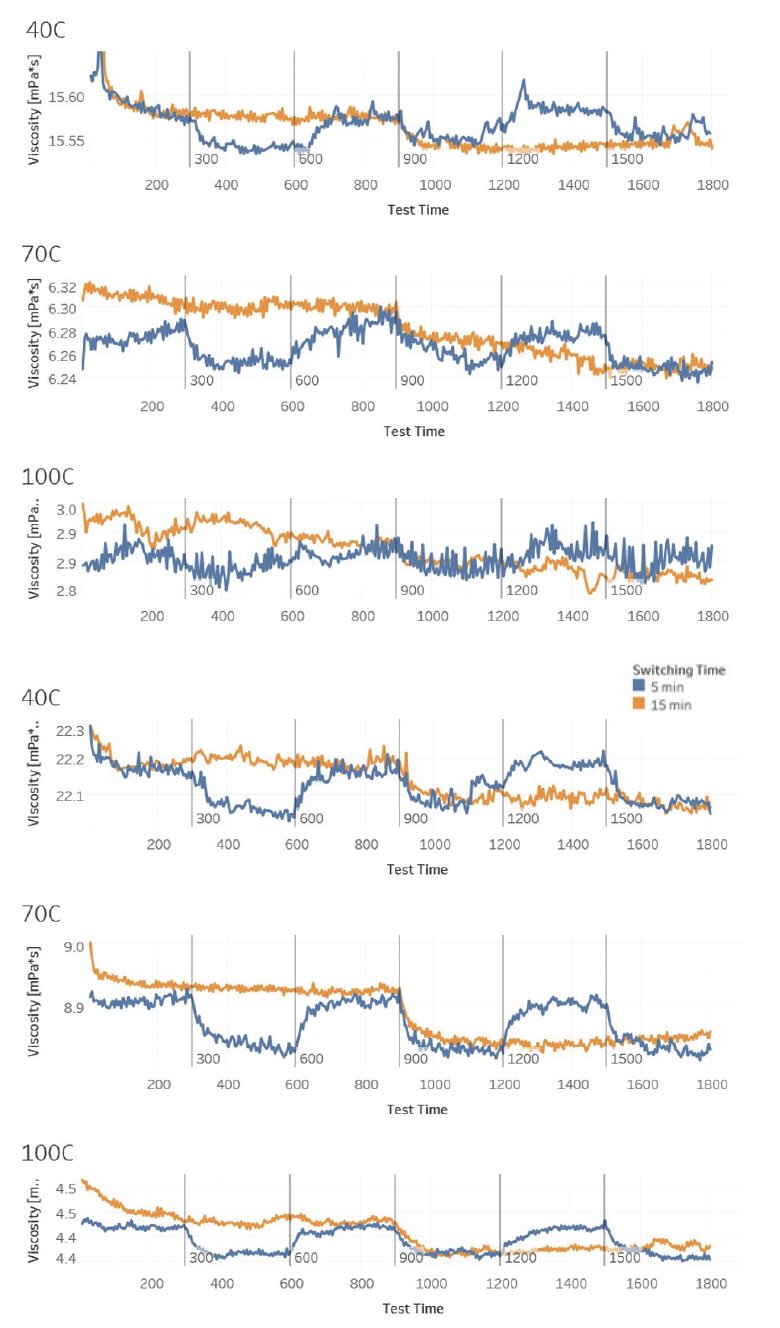
Figure 13. Switching experiment of different ATFs. Figure courtesy of Southwest Research Institute.
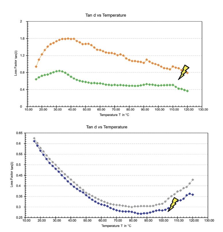
Figure 14. Parallel plate testing results. Figure courtesy of Southwest Research Institute.
Results of switching experiments show that power on or off affects viscosity immediately. Dr. Lee explains: “Figure 14 shows test results of switched experiment with different ATFs. What we have here is blue lines where we switched at five minutes and orange lines where we switched at 15 minutes. And this is the viscosity at 40, 70 and 100°C. The graph shows that we can turn on and off power, and we can literally turn on and off the viscosity change. It really is immediate and, sometimes it lasts a little bit. The lower part of the graph shows that it took some time to respond and the viscosity to come back up after this switch. But generally it’s almost instantaneous it really is just like turning on and off a light switch.”
Figure 14 shows test results on parallel plate of two different grease types. Spark images show electrified lines, and the rheological changes can be seen from electrification. Dr. Lee explains: “We’re seeing a difference in loss factor, so tan delta, which is the modulus over the storage modulus, and that’s starting to change the rheological behavior of these greases through electrification and non-electrification.”
•
Frequency sweep to temperature sweep curve at 10 Hz
•
Applied 30 V, 2A DC
•
Loss factor (tan delta) = loss modulus/storage modulus (G”/G’)
•
Loses elasticity with applied DC
Testing conclusions:
Dr. Lee says: “An application of DC or AC current increases wear over non-electrified tests, and it changes the friction response. In all cases, it increased the traction. Friction response was slightly different, and it changes this for both fluids and greases. This has been seen in other universities and national labs—it’s a common phenomenon; it’s something that’s happening. We have seen the end result of it in electric drive units that we’ve had to tear down and look at here. It shows there’s options to test lubricants in electrified environments and opportunities to develop lubricants specifically for these environments. There’s lots of work that needs to be done, both to define test parameters and understand why electrification changed the response of the tribosystem. There’s still a lot of work out there that needs to be done.”
To summarize:
•
Application of DC or AC current:
•
Increases wear over non-electrified tests
•
Changes friction and traction responses
•
Changes fluid and grease properties
•
These responses have been seen by other establishments:
•
Universities
•
National labs
•
Shown options to test lubricants in electrified environments and opportunities to develop lubricants specifically for these environments
•
Lots of work needed to define test parameters and understand why electrification changes response of tribosystems
Summary
There are some commercially available electrified rigs available, with more coming. In addition, many aftermarket electrified (AE) rigs available for use today. Electrification of rigs results in:
•
Variable changes in friction
•
Variable changes in film thickness (different lubricants, used, new)
•
Increased wear over non-electrified in all tests—generally DC more than AC
•
Changes in lubricant behavior
Unfortunately, there is noticeably small amount of research in this field to date and a very few published papers. There is a need to test lubricants in electrified environments and opportunities to develop lubricants specifically for these environments.
FOR FURTHER READING
1.
Lee, P.M., Sanchez, C., Frazier, C., Velasquez, A. and Kostan, T. (2023), “Tribological evaluation of electric driveline lubricants in an electrified environment,”
Front. Mech. Eng., 9. Available at
https://doi.org/10.3389/fmech.2023.1215352.
2.
Lee, P.M., Sanchez, C. Moneer, M. and Velasquez, A. (2024), “Electrification of a Mini Traction Machine and Initial Results,”
Lubricants, 12 (10), 337. Available at
https://www.mdpi.com/2075-4442/12/10/337#.
Dr. Yulia Sosa is a freelance writer based in Peachtree City, Ga. You can contact her at dr.yulia.sosa@gmail.com.