Electric motors
By Tyler Housel, Contributing Editor | TLT Lubrication Fundamentals November 2025
The four Maxwell equations that give all the information needed to understand classical electromagnetics.
Electric motors may be the most common (nonliving) motive device on Earth. They operate efficiently across a wide temperature range in environments from the deep ocean to outer space with a simple design that requires little maintenance. Electric motors come in all sizes and are always available at the flip of a switch. Like tribologists, they are one of the unsung heroes of our industrialized world.
There are a few different designs, but all electric motors use a rotor-stator configuration to convert electric current to rotational motion. Generally, the only lubrication point is a set of bearings on each side of the rotor shaft that allow free rotation, manage the load, reduce friction and ensure that the rotor and housing remain aligned. But the true magic happens in the stator where an applied current creates magnetic fields in free space that cause rotation by alternately attracting and repelling magnets (permanent or electromagnets) in the rotor.
Last month’s TLT Lubrication Fundamentals article concluded with the four Maxwell equations that give all the information needed to understand classical electromagnetics. These equations define charge, electric and magnetic fields and show how they interact. Eventually people figured out how to get the fields to cooperate and extract motion out of current (motors) as well as current out of motion (generators). Rather than assume everyone memorized the Maxwell equations, it’s best to start by showing them again in Table 1. The key to making an electric motor is in the fourth equation because a current (i) passing through a wire creates a magnetic field (B). Hans Christian Oersted conducted the earliest known experiments in this area and produced a magnetic field strong enough to deflect a compass needle at close range. Although this was an interesting effect, it requires a much stronger magnetic field and some creative engineering to power an electric car.
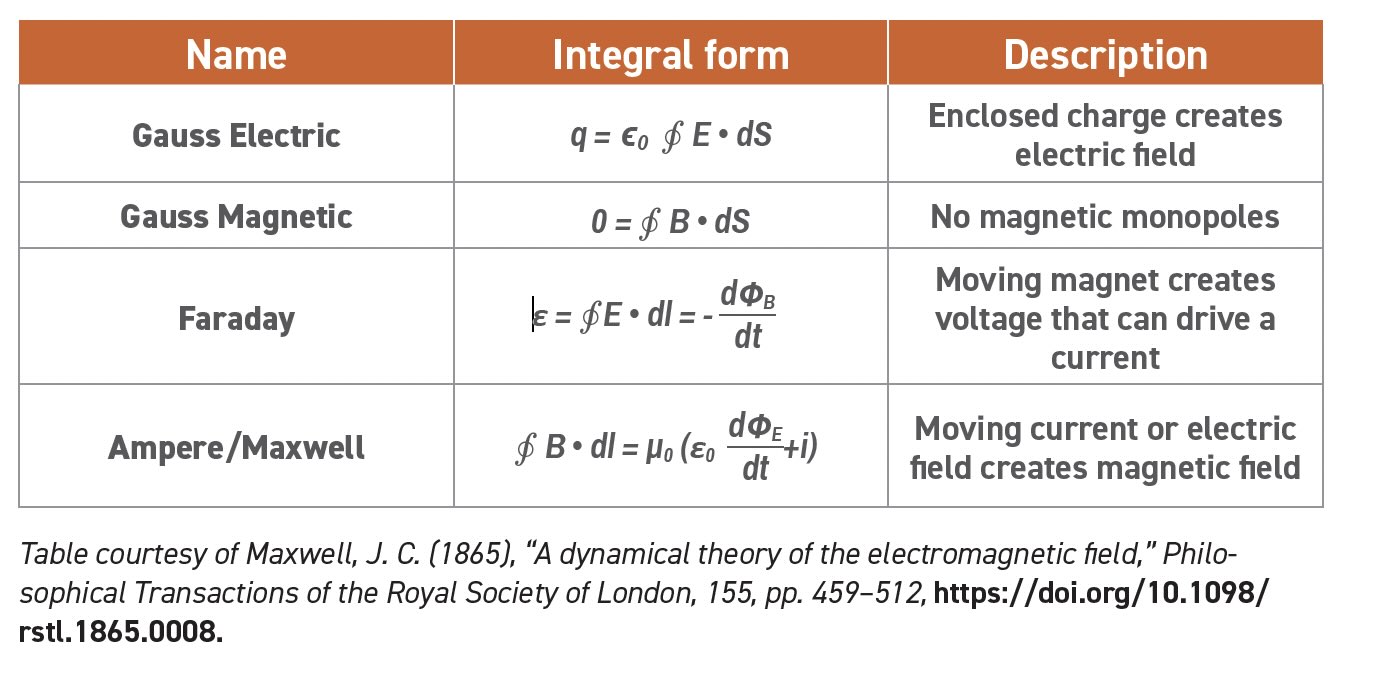
Table 1. Maxwell’s equations
Wires
The middle and left side of the periodic table are home to the metal-forming elements like iron and aluminum that have a one or more electrons beyond the number needed to fill their lowest energy electron shells. Oxygen readily takes up these extra electrons to form stable oxides which make up most of the rocks and minerals on Earth.1 Rocks do not conduct electricity because the electrons are locked into ionic or covalent bonds between neighboring atoms. On the other hand, metals are conductive because extra electrons are loosely associated with individual atoms and can easily move from one atom to the next.
Ancient Sumerians learned to make metallic copper by smelting malachite (copper carbonate hydroxide) with charcoal to drive off the carbon and oxygen atoms.2 Copper was interesting and valuable, so ancient metallurgists experimented with other ores and eventually developed bronzes, iron and other metals. But they made metal for weapons, tools and jewelry; electrical conductivity was just a happy accident. And because many metals are ductile, they can be formed into wires that conduct electricity over a long range with little resistance.
Permanent magnets
Quantum mechanics teaches that electrons are defined by four quantum numbers that describe their energy level, orientation and spin. Electrons fill the lowest energy levels first and the aforementioned “extra” electrons end up in large, unfilled orbitals. These electrons are charged particles and can interact with a magnetic field. Aluminum (for example) is not magnetic because the electron magnetic fields cancel out. However, some metals like iron, cobalt and nickel are attracted to a magnet because their electrons can align with the magnetic field as discussed in last month’s TLT Lubrication Fundamentals article.3
When the magnet is removed, the alignment disappears as most fields return to their disordered state. But if the external field is strong enough to alter the crystal structure, the magnetic regions can be frozen in place, and the iron will become a permanent magnet.4 The alignment can last a long time under ambient conditions. Geologists have even used the orientation of naturally occurring magnetic crystals to document changes in the Earth’s magnetic field occurring over the last 250 million years.
Everyone is familiar with classic iron magnets, and technologists have learned to create much stronger permanent magnets with improved processing techniques and alloys that often use rare earth elements such as neodymium. These are more expensive but can significantly improve the performance of an electric motor.
Electromagnets
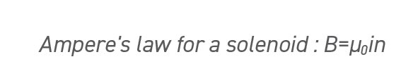
Permanent magnets are useful but not nearly as clever as electromagnets. Remember from the Maxwell equations that a current in a wire will cause a magnetic field. The "right-hand rule" teaches that our fingers show how the field wraps around the wire when a current flows in the direction of our thumb around the wire as shown in Figure 1. If the current flows through a loop of wire as in Figure 2, notice that all of the field lines inside the loop point downward (toward a North pole). A solenoid is a type of electromagnet made from a coiled wire that allows the magnetic fields of all the loops to point in the same direction. Applying Ampere’s law (the reference can provide the detailed calculation), the magnetic field inside the solenoid is proportional to the current and the number density (number of turns per unit length) of loops.5
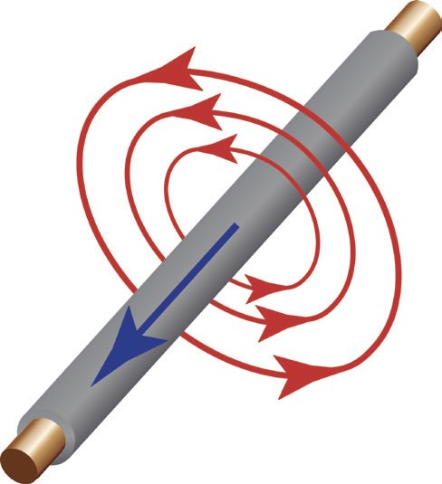
Figure 1. Magnetic field lines around a wire carrying a current. Figure adapted from User: Stannered, CC BY-SA 3.0, via Wikimedia Commons.
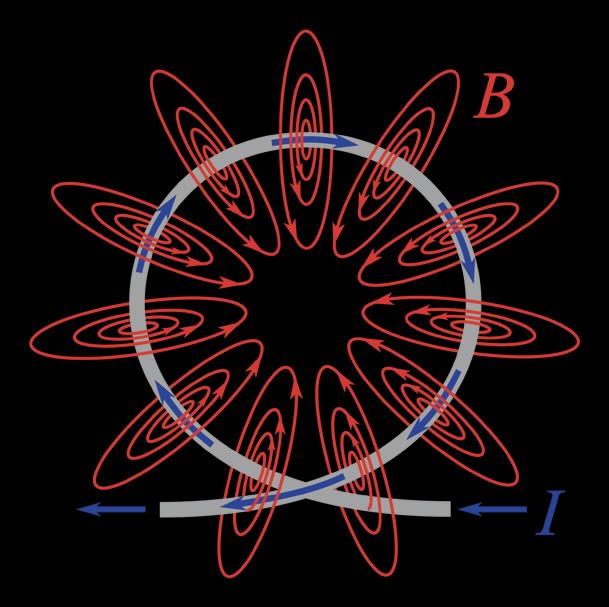
Figure 2. Magnetic field lines around a loop of wire. Figure courtesy of Chetvorno, CC0, via Wikimedia Commons.
There are two important takeaways from this equation. First, the magnetic field increases with every loop so that you get the same magnetic field from 100 loops of a 1 amp current or one loop of a 100 amp current. We’ve all been shocked with 5,000 volts of static electricity, but old electricians have been known to say “it’s not the voltage that kills you, it’s the current.”6 If a young electrician ignores this advice, they don’t get to be an old electrician. So electric devices like the motor shown in Figure 3 are much safer using dense coils of wire instead of higher current to maximize the magnetic field.
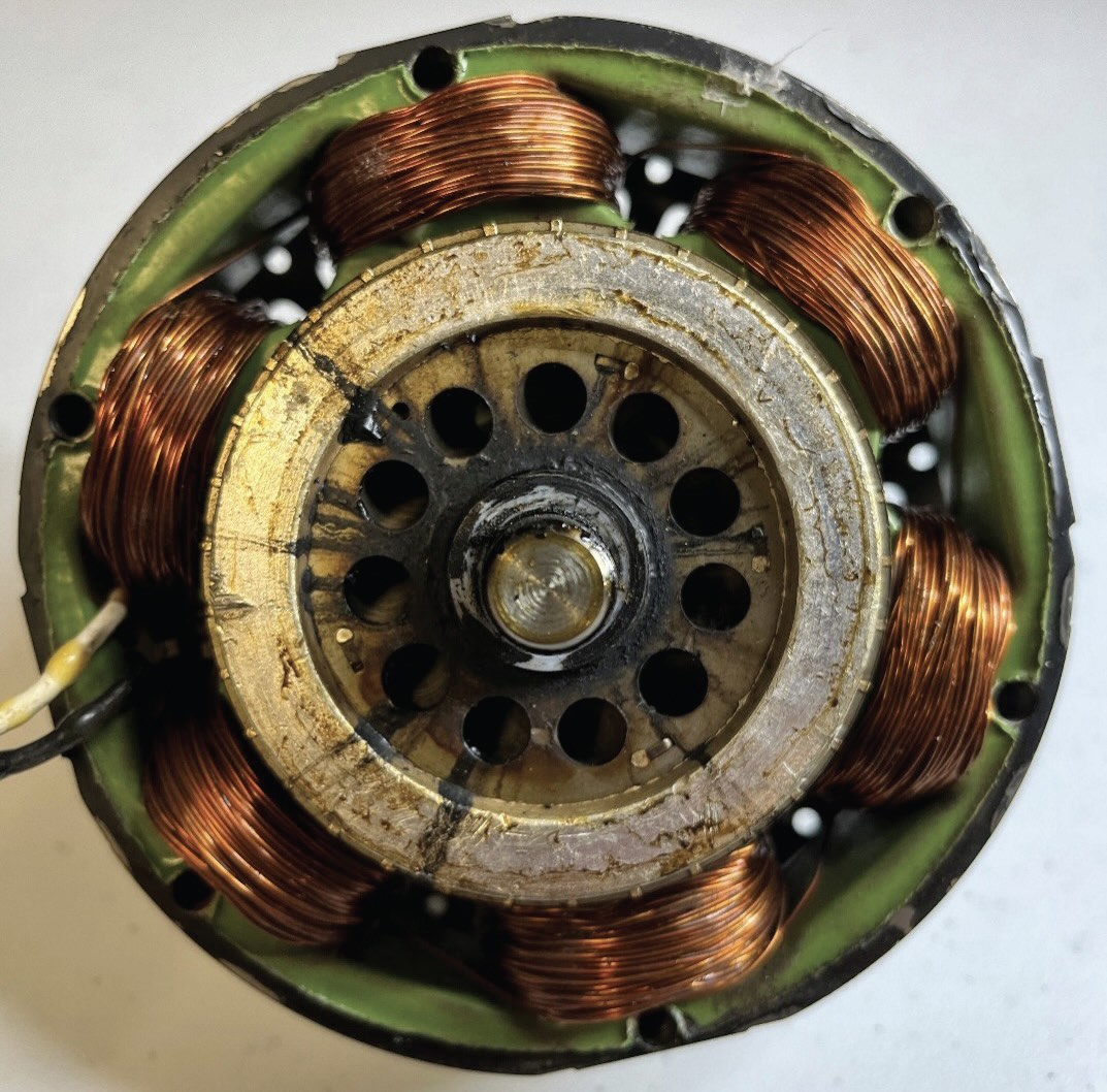
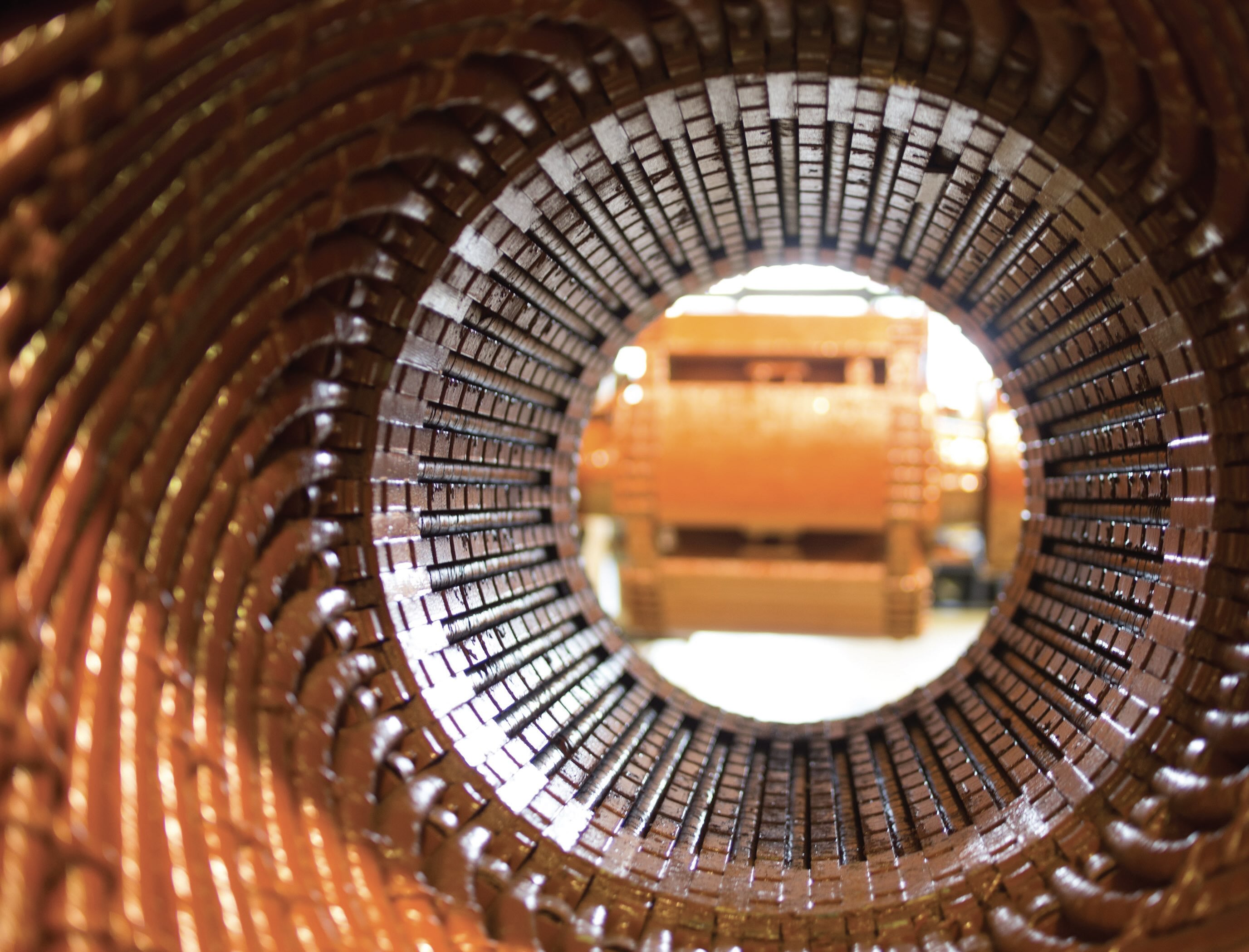
Figure 3. Coils of wire increase the magnetic field strength.
The second takeaway is that the magnetic field switches direction when the current is reversed as demonstrated with a simple experiment in Figure 4. The battery pack provides around 6 volts of DC current that flows from the red to the black lead wires (electrons flow black to red). When the red lead is attached to the top of the solenoid coil, current flows downward (clockwise as seen from the top) creating a North pole at the bottom of the coil. This attracts the South end of the compass needle because the Earth’s North magnetic pole is near the geographic South pole. When the red lead is attached to the bottom, the current and field directions are all reversed and the compass needle now points North. With all the conventions for North/South/positive/negative, it can be hard to remember which way is up. Scientists use different right-hand rules in electromagnetics, vector multiplication, torque rotation and stereochemistry to determine directions in three dimensions. I remember hearing that left-handed students had an advantage in physics because they could use the right-hand rule and write at the same time.
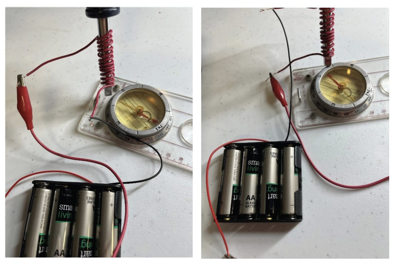
Figure 4. The magnetic field flips when current is reversed.
Electric current to rotation
The key elements of an electric motor are shown in Figure 5. In this simple design, there are an even number of electromagnets in the stator (six in this diagram). They are wired so that the current paths of adjacent electromagnets are in the opposite direction so an electromagnet showing a North pole is always between two showing South poles. Permanent magnets are usually used in the rotor and again they alternate from North to South facing the stator. Although the stator is physically stationary, the fields are determined by the current which moves through the wires.
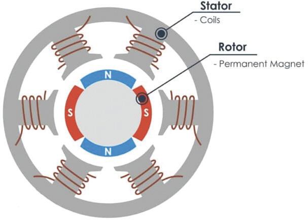
Figure 5. Schematic of an electric motor or generator. Figure courtesy of www.mechatronics.com, CC BY-SA 4.0, via Wikimedia Commons.
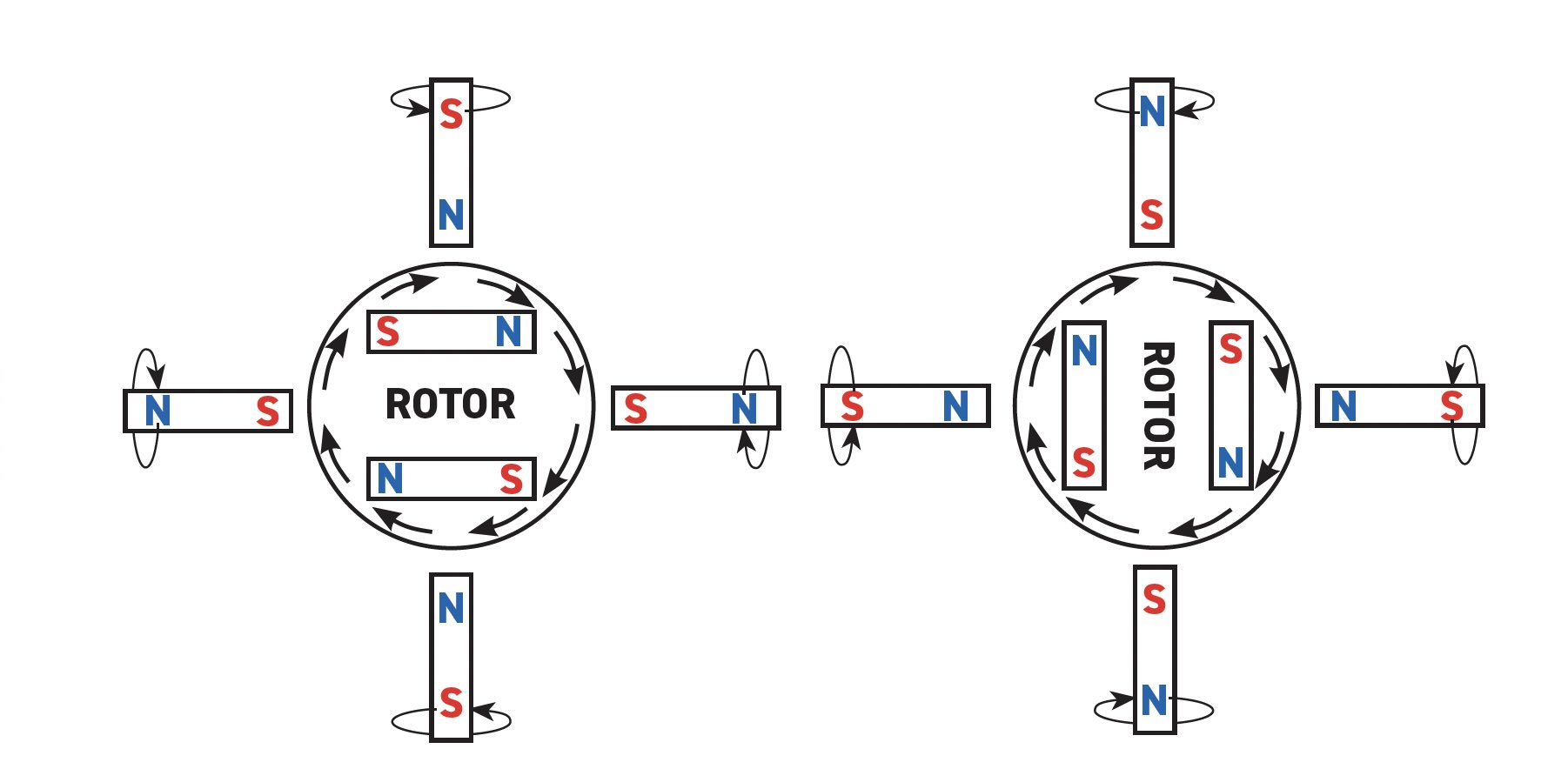
Figure 6. Reversing current drives the rotor clockwise.
The left side of Figure 6 shows the magnetic orientation when the current is switched on. Of course, opposite poles attract and same poles are repelled, which pushes the rotor clockwise. But as the rotor arrives at its most stable (South up) position, the current reverses and flips the fields of the electromagnets. Now the stable position has moved ¼ turn clockwise and the rotor follows. Like a horse chasing a carrot on a stick, the rotor continues to rotate as long as the current reverses.
Types of electric motors
Electricaltechnology.org lists at least 30 different types of electric motors, and they are grouped into two main categories: AC and DC.7 With a third type (AC/DC) that is often used for generating loud music.
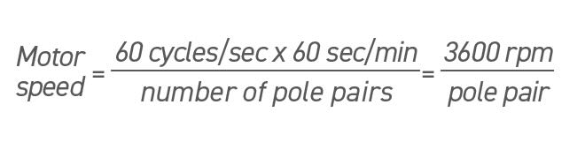
AC motors run on alternating current and are a natural fit for producing reversing fields in the stator. A typical household electric plug connects to a 60 Hz alternating electric current. Each half cycle drives the rotor from a North to a South pole, so a motor with four alternating poles needs two cycles to make a complete rotation. A synchronous AC motor uses 60 Hz current to drive a motor at 3,600 rpm or integral fractions depending on the number of poles. This design is efficient but the motor can only spin at one speed.
Direct current (DC) always flows in the same direction, so DC motors use different techniques to change the current flow as the rotor spins. One mechanical design uses brushes and a split ring commutator to switch the direction of the current. If the current enters from the left, it can be directed up or down depending on the position of the commutator as shown in Figure 7. Since the rotation causes the current to reverse, both must occur at the same rate, and the motor’s speed is determined by the electric energy input and load.
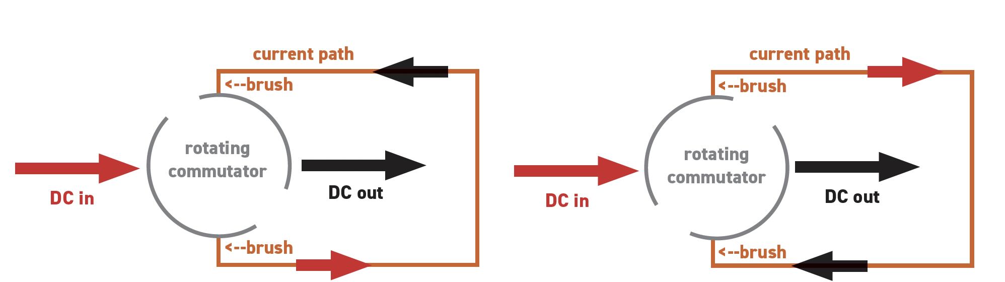
Figure 7. Rotating commutator reverses the current path.
These basic designs lie at the heart of most electric motors, while many innovations in the mechanical and electronic configuration optimize their performance to allow them to perform in an amazing array of applications. Electric generators are a closely related topic and complete this introduction to electromechanics.
Bonus topic: Electric generators
Most people plug devices into electric outlets without thinking about how the power is generated. Now that we’ve covered electric motors, it might be obvious that a generator operates on the same principle but in reverse. Although windmills, gas turbines and bicycle cranksets spin at much different speeds, they all provide rotational energy. If we use this energy to drive the rotor in Figure 5, the permanent rotor magnets will create an electromagnetic field (EMF) in the coiled wires according to Faraday’s law (see Table 1). When the circuit is closed, the EMF will push an induction current through the wire. Classic TV fans will remember that the electric power on Gilligan’s Island was provided by a bicycle powered generator. This gives me a great idea for a retirement project.
SI electromagnetic units
The International System of Units (SI) defines seven base units with exact values determined by international agreement. All other measurements are derived from these seven. The May TLT Lubrication Fundamentals article showed how meters (m), seconds (s) and kilograms (kg) are combined to measure critical tribological concepts such as motion, work, pressure, energy, viscosity and friction.8 Adding the Ampere (A or amp) expands the SI measurement system to cover electromagnetics as shown in Table 2.9 Although all of these measurements are derived from the base units, be forewarned that it is virtually impossible to think of the physical significance of combinations like [kg m2/A2 s3], which is better known as an Ohm.
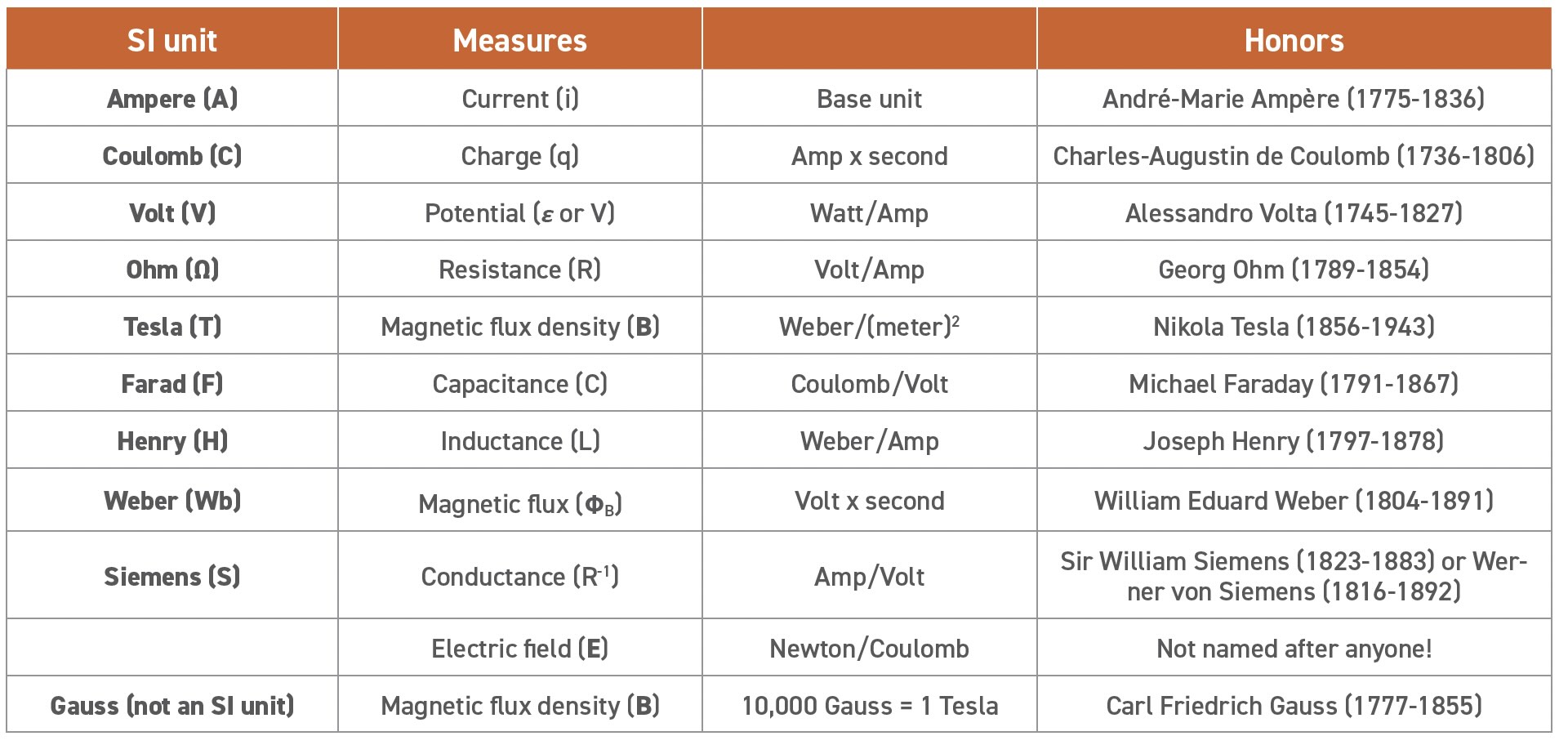
Table 2. SI electromagnetic units
REFERENCES
1. Housel, T. (2025), “The periodic table,” TLT, 81 (3), pp. 30-34. Available at www.stle.org/files/TLTArchives/2025/03_March/Lubrication_Fundamentals.aspx.
2. www.copper.org
3. Housel, T. (2025), “Maxwell’s field equations,” TLT, 81 (10), pp. 30-36. Available at www.stle.org/files/TLTArchives/2025/10_October/Lubrication_Fundamentals.aspx.
4. www.madehow.com/Volume-2/Magnet.html
5. www.hyperphysics.phy-astr.gsu.edu/hbase/magnetic/solenoid.html
6. www.electronicproducts.com/things-only-electrical-engineers-know-its-not-the-voltage-that-kills-you/
7. www.electricaltechnology.org/2021/01/types-of-electric-motors.html
8. Housel, T. (2025), “The metric system,” TLT, 81 (5), pp 28-32. Available at www.stle.org/files/TLTArchives/2025/05_May/Lubrication_Fundamentals.aspx.
9. www.nist.gov/pml/owm/metric-si
Tyler Housel is a technologist for Hnuco Technologies and is based in Lansdale, Pa. You can reach him at tylerhousel@comcast.net.