Compressor lubrication fundamentals
By Dan Holdmeyer, Contributing Editor | TLT Lubrication Fundamentals February 2024
There are details to watch out for when lubricating a compressor.

At the end of the January TLT Lubrication Fundamentals article, we discussed various compressor designs and how some compressors utilize multiple stages to get to higher pressures. We also noted that we needed to cool the air between the stages for efficiency and safety reasons.
I started to explain the relationship between gas pressure, volume and temperature using the various gas laws of Boyle’s, Charles’ and Gay-Lussac’s leading to the Ideal Gas Law: PV=nRT (pressure times volume equals number of molecules times R the gas constant times temperature). Two things happened—I filled up a whole page without actually concluding my explanation of the need for cooling and as I reread the page, I nearly fell asleep. So, I’m going back to my Missouri farm boy experience to understand multi-stage and single-stage compressor system design needs.
I remember inflating a wagon tire in the field with a hand driven tire pump. By the time the tire was inflated properly, the cylinder on the tire pump was so hot I could not hold onto it with my bare hands. Compressing air not only increases the pressure but also raises the temperature— significantly! In the field I was only raising the tire pressure to 35 psig (Pounds per Square Inch Gauge pressure, or pressure above atmospheric pressure). In many industrial applications, air pressure is raised to between 90 and 110 psig, and that raises the high-pressure air temperature to around 500 °F, if not cooled.
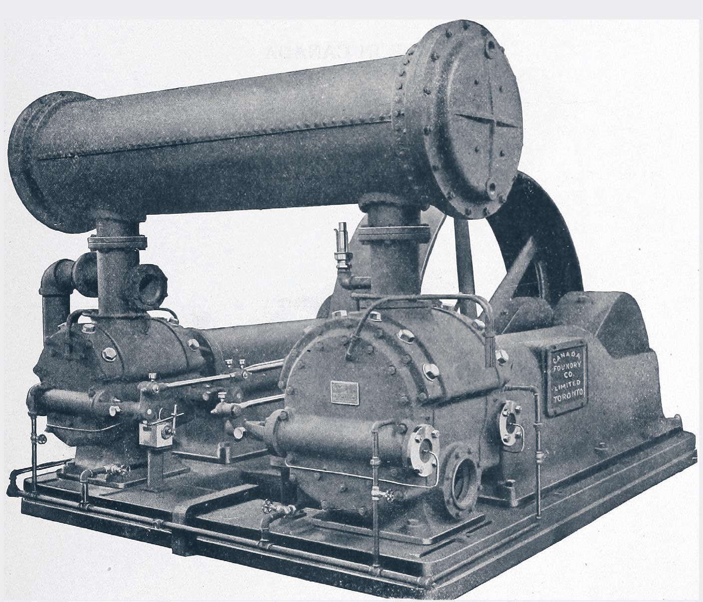
However, if the air is compressed to 110 psig in two stages, the final discharge temperature from the second stage will be around 245 °F, with the air being cooled between the stages. This is a more reasonable temperature for the compressor seals, lubricants and even the metallurgy to handle. Figure 1 shows a two-stage reciprocating compressor where you can see the intercooler connecting the two cylinders. Also note the cylinders’ sizes are different. The first stage is the larger cylinder on the right. The compressed volume of pressurized air from the first stage is cooled by the intercooler before it goes to the smaller second stage cylinder on the left, where the air is compressed to an even smaller volume and higher pressure. Higher pressure compressors may have more stages, with each cylinder, in the case of reciprocating compressors, being smaller than the previous stage’s cylinder with higher pressure. A four-stage compressor is the most I’ve come across. I’ve also seen multi-stage centrifugal, axial flow and rotary screw compressors.

Figure 1. Two-stage reciprocating compressor.
Back on the farm, we did have a single- stage shop air compressor. It did not need multiple stages nor an intercooler even though we would run the tank air pressure up to 100 psig. This was doable because the compressor was not compressing the air to 100 psig in one stroke of the compressor piston. It was taking relatively small amounts of atmospheric air condensing to a few pounds above atmospheric pressure. Continuing to push more and more compressed air resulted in the 100 psig in the tank. The temperature would rise but not nearly as much as compressing the air to 100 psig in one stroke.
Another concept I learned from the shop air compressor was that liquid water comes out of the air when the air is pressurized and then cooled or allowed to cool. Whenever the compressor was not in use for more than a day, we released the compressed air from the tank to remove the water from the tank. If the water was left in the tank, the tank would corrode over time and eventually fail, i.e., develop a hole. Thus, after most air compressors, the discharge air goes through a cooler and separator to separate the water from the air. Water not only can cause corrosion throughout the system but will cause erratic operation of, and damage to, the pneumatic tools powered by the air.
Additionally, a receiver is often in place before the point of use of the pressurized air and after the cooler and separator. The receiver can store pressurized air allowing the compressor to shut down occasionally, when pressurized air demand is low. Additionally, the receiver will dampen the pulsing of air pressure resulting particularly from a reciprocating air compressor, or multiple compressors in a system, starting and stopping.
The cooler and separator not only remove water from the compressed air but are designed to remove the oil used in the compressor carried downstream with the compressed air. Although the oil does not lead to corrosion throughout the system, it can lead to liquid pooling in low points in the compressed air piping stopping air flow, can lead to Occupational Safety and Health Administration (OSHA) violations if too much oil is dispersed in the air and will lead to excess oil consumption.
The compressor crankshaft and piston rod bearings in Figure 1 are splash lubricated via the lubricant in the crankcase sump. The cylinders are closed off of the crankcase and are lubricated via a separate mechanical force feed lubricator (MFFL).
Single-stage shop air compressor cylinders are open to the crankcase and the oil is splashed up to lubricate the cylinder, rings and bearings. Thus, some oil does get into the compressed air. The lubrication requirements in the crankcase are mild, as they are for the cylinders and rings in these relatively small shop compressors running intermittently. A rust and oxidation inhibited (R&O) oil ISO VG 100 or 150 is often used in these compressors. Many of the owner’s manuals recommend a nondetergent SAE 30 oil, which an R&O ISO VG 100 falls into that category.
Lubrication requirements of the cylinders and rings can be much more severe in larger, higher pressure, continuous running reciprocating compressors (see Figure 1) and may require a lubricant with higher performance characteristics. Additionally, splash lubrication from the crankcase is not reliable enough for properly lubricating the cylinders and rings of larger compressors. Thus, an MFFL is used to provide lubricant to the cylinders and rings. Many MFFLs have a separate reservoir to allow for a different lubricant to be used in the cylinders versus what is in the crankcase.
The MFFL meters out precise amounts of lubricant to each cylinder and any rod packing that may be part of the compressor. Too little oil results in excessive cylinder and ring wear and may allow corrosion of the metals from any moisture in the air. Too much oil in the cylinder will form oxidized oil deposits in the cylinder and ring groves, but more critically on the exhaust valves. Eventually the deposits prevent the closing of these exhaust valves reducing the compressor efficiency by allowing compressed air to return to the cylinder and be compressed again. This continual recompressing of the air raises the temperature higher to the point of the deposits on the exhaust valves getting “red hot” and possibly igniting the atomized oil in the compressed air. This results in either an explosion or fire in the compressor. Neither are good. It is critical to follow OEM recommendations on the oil feed rate of each lubrication point the MFFL lubricates.
Rotary screw compressors have replaced reciprocating compressors in many manufacturing plants because of their reliability and efficiency. The two mating internal rotors may be driven by precision machined gears to maintain the small clearances between the rotors relative to each other and the housing. The gears and bearings must be lubricated, but the lubricant also may be injected into the air intake to help seal those clearances. When oil free compressed air is needed, oil is not injected in the air. Another variation is that one rotor is driven via external mechanical driver, and it drives the other rotor. No gears are used in this application, but a lubricant injected into the air is needed to protect the rotors.
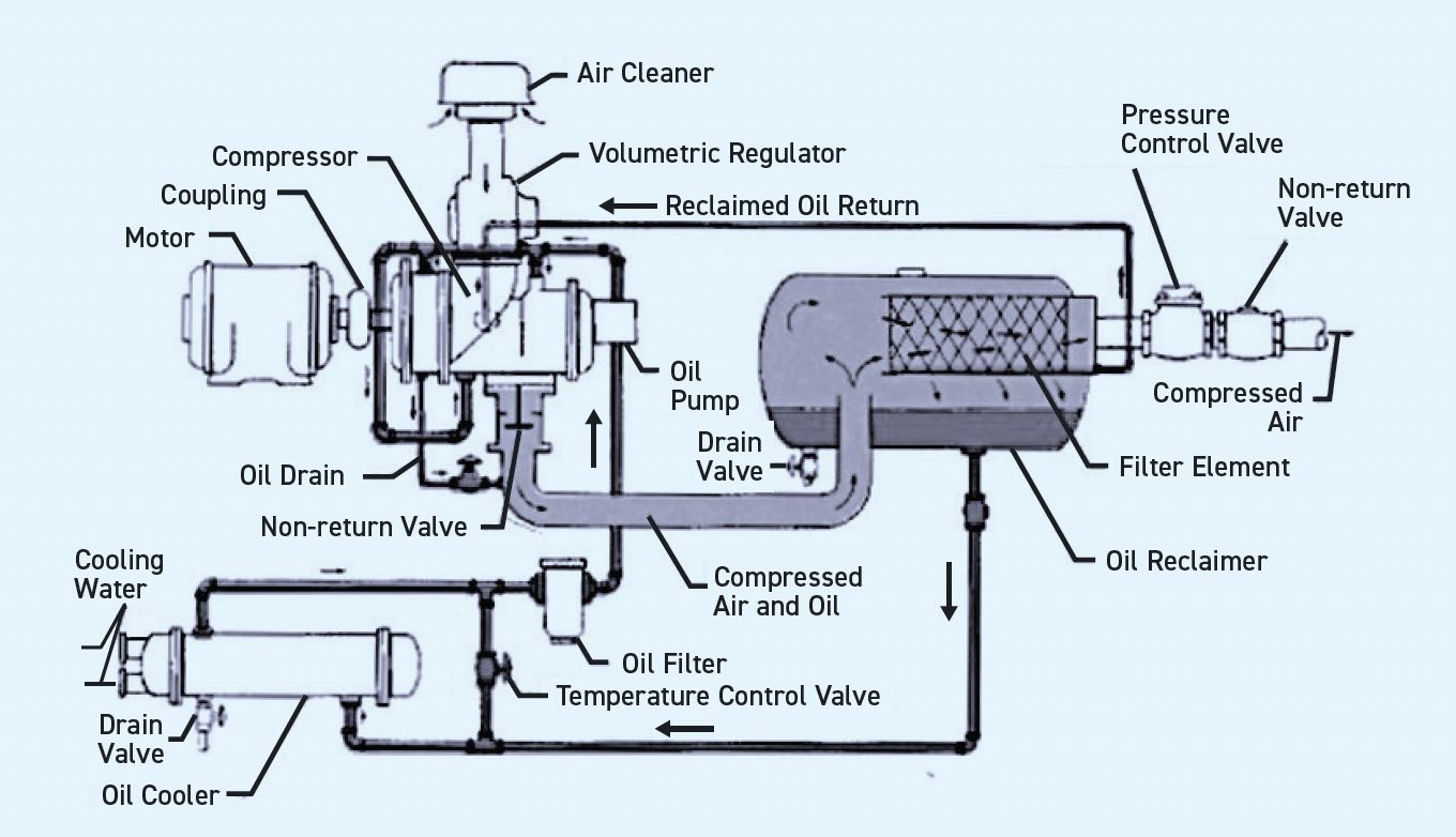
Figure 2 shows a typical rotary screw compressor lubrication circulation system with separator and cooler. An oil pump driven by the compressor lubricates the bearings and gears on each end of the compressor and into the air intake. Compressed air, with a small amount of oil in it, then enters the separator where the oil and any water condensate are removed from the air before it goes to a receiver (not shown) where more liquids are allowed to drop out. An oil cooler not only maintains the proper oil temperature and viscosity but also helps remove water.

Figure 2. Rotary screw compressor lubrication system. Figure courtesy of the STLE Annual Meeting Basic Lubrication course compressor module.
Rotary lobe compressors require lubrication of their bearings and timing gears, usually by splash lubrication from the sump housing the gears. The bearings on the opposite end of the compressor from the geared side may be grease lubricated. Synthetic lubricants may be used in rotary lobe compressors, even though the oil is not in contact with air because the application is hot, and the oil reservoir is relatively small. A circulating lubricant system may be incorporated for large compressors or high temperature applications.
The lubrication points on dynamic compressors, whether they are centrifugal or axial flow, are critical but relatively simple compared to compressors whose lubricants encounter the gas being compressed. Usually an ISO VG 32, 46 or maybe 68 R&O oil is recommended for these dynamic compressors.
Air compressor lubricant formulations require excellent oxidation resistance, particularly when the lubricant is injected into the air. Corrosion inhibitors and demulsifiers also are critical because of the water content in compressed air. Air release and anti-foam characteristics enable recirculation of the oil within the system.
Many air compressor oils are formulated with synthetic bases stocks to extend lubricant life from a common 2,000-hour oil drain interval (ODI) with a mineral-based oil to 10,000+ hours with synthetic based fluids such as diesters, polyol esters, polyalphaolefins (PAO), silicones and polyglycols.
We’ve mostly been discussing air compressors, but a major consideration in what lubricant is used in compressors is the gas being compressed if the lubricant contacts the gas. Chemically active gases such as chlorine, hydrogen sulfide, hydrogen, oxygen and air may require no lubricant comes in contact with the compressed gas. Oxygen for breathing applications, such as a scuba tank, is a good example. And, yes, air is considered chemically active because of the oxygen and nitrogen potential reaction with lubricants to form deposits and thus the use of synthetic lubricants to extend the lubricant life.
Compressing hydrocarbons, such as natural gas, refinery gas and acetylene, raises another somewhat unique challenge. Since mineral oils and some synthetics also are hydrocarbon based, the compressed hydrocarbon gas will easily comingle with the lubricant. Most hydrocarbon gases being compressed are made of much shorter hydrocarbon chains than lubricants and, thus, will lower a hydrocarbon-based lubricant’s viscosity out of recommended range. Therefore, other base fluids may be required such as polyglycol.
Lubricant base stock is particularly critical when compressing the various fluorocarbon and ammonia refrigerants for refrigeration applications. Polyol esters are commonly used with hydrofluorocarbon (HFC) refrigerants, whereas naphthenic mineral oils or PAOs are used with ammonia.
Compressor lubrication is quite simple for relatively low-pressure air compression, but when you get into higher pressures and other gases compressed, the lubricant selection gets more complicated. Hopefully it is helpful to know what to watch out for when lubricating any compressor.
Dan Holdmeyer is retired from Chevron Lubricants and is based in Washington, Mo. You can reach him at dan.holdmeyer@gmail.com.