Bearings
By Dan Holdmeyer, Contributing Editor | TLT Lubrication Fundamentals October 2023
The best lubrication regime depends on the type of bearing and the application in which it is used.
One of the simplest types of bearing is the plain bearing, or journal bearing, where a shaft is supported by bearing material shaped concentrically with the shaft. The length of the shaft that is within the bearing width is called the journal, and, thus, the name journal bearing (see Figure 1). The bearing metallurgy ideally is softer than the shaft metal. This design dictates that the bearing wears out before the shaft, which is ideal in that it is far less expensive and difficult to replace the bearing compared to replacing the shaft. Proper lubrication, however, will extend the bearing life, possibly to the life of the equipment.
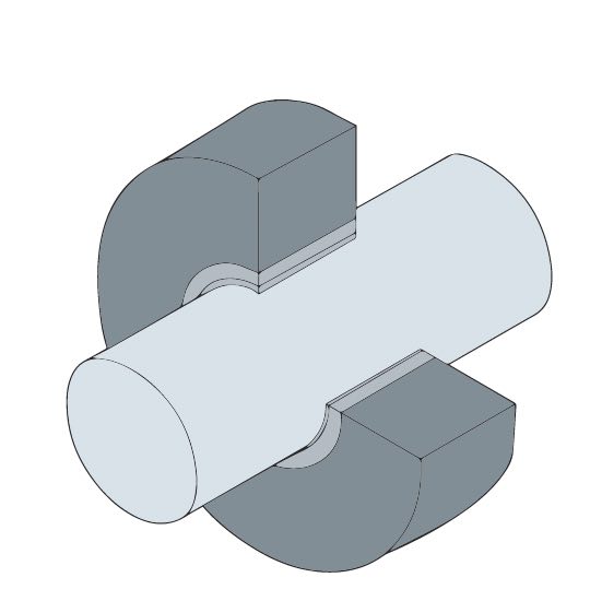
Figure 1. Plain, or journal, bearing.
Linear bearings, another form of journal bearings, are often overlooked as bearings. They may also be called slides, guides or ways.
Rolling element bearings are comprised of an inner race, an outer race and elements that roll between the two races (much more complicated than a plain bearing). The rolling elements are held in place by a cage to keep them evenly spaced between the inner and outer races (see Figure 2). These rolling elements reduce bearing friction with minimal lubrication and are sometimes referred to as anti-friction bearings, but that does not mean no friction; thus, we still need to lubricate and protect these bearings.
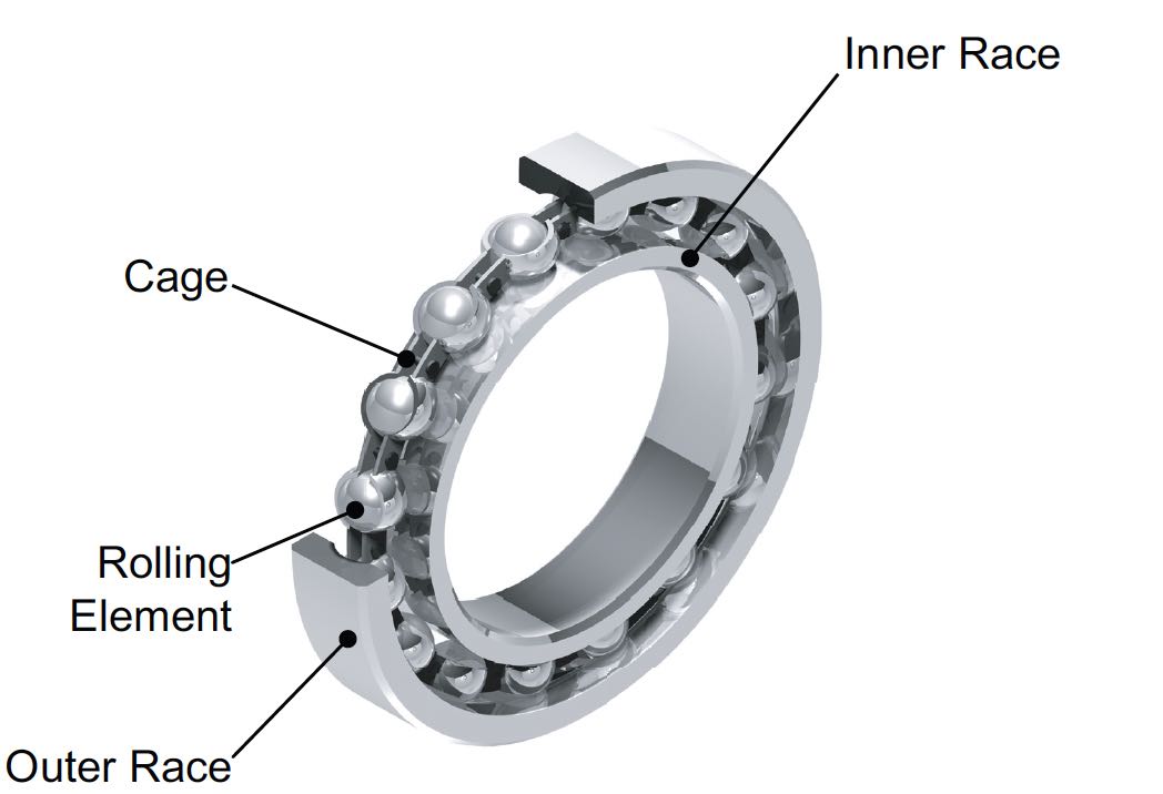
Figure 2. Rolling element bearing components.
Rolling element bearings are classified by the shape of the rolling elements incorporated. Figure 3 shows just a few bearing types. Some bearings have two rows of rolling elements between the races and are simply called “double row,” or “double barrel roller,” bearings, for example. Double row bearings are used to support heavier radial loads relative to their single row counterparts. Additionally, roller bearings in general have greater load carrying capacity than ball bearings.
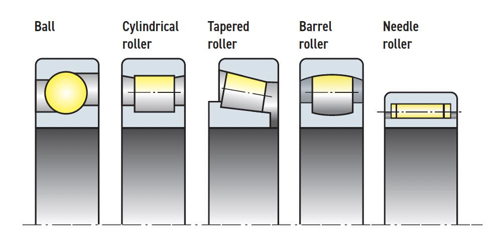
Figure 3. Various rolling element types.
Most often the outer race is held stationary with the inner race attached to a rotating shaft. Common applications are in turbines and gearboxes where the bearings support the rotating shafts. The steer axle bearings of rear-wheel-drive cars are an example of the inner race remaining stationary and the outer race rotating. These bearings not only carry a radial load from the weight of the vehicle but also must carry axial load when the car turns right or left. The bearings need to keep the wheel from sliding left or right off the axle. Tapered roller bearings are commonly used in this application and are frequently referred to as “Timken” bearings, after one of the first companies that designed and manufactured automotive tapered roller bearings. Figure 3’s tapered roller bearing image shows the taper of the rolling element and the angular contact of the races with the rolling elements. Looking at the orientation of the image, one can see that the bearing would not allow the outer race to move axially from right to left. However, a force from left to right would separate the bearing. Therefore, two of these type of bearings are placed on the steer axle, one to handle thrust to the right and the other to handle thrust to the left, keeping the wheel on the shaft.
The ball bearing in Figure 3 also can handle some axial load due to the opposing “lips” of the inner and outer race. This particular configuration would resist a left to right thrust on the outer race. The barrel roller bearing also can resist some axial thrust. Neither of these will resist a great deal of axial load as the edges on the races will wear more rapidly and eventually fail. Needle and cylindrical roller bearings are used in radial load applications only—no axial load.
A side note on barrel roller bearings is, because of the shape of the rollers and the outer race, they can handle slight shaft misalignment without damage. These double row barrel roller bearings are common in the paper making industry. The bearings can withstand slight flexing of the large drying rolls suspended within the paper machine.
Now let’s get back to axial thrust loads. Helical gears and turbines produce significant axial loads. Thrust bearings are commonly used in these, and other applications that generate thrust loads, to keep the rotating shafts in place. Thrust bearings do not support any radial load. The races are orientated 90 degrees to the races of radial load bearings (see Figure 4). Another type of thrust bearing used in many turbine applications is the tilting pad thrust bearing. The tilting pad thrust bearing uses tilting pads to develop an oil film wedge against a thrust collar to resist the axial load versus rolling elements.
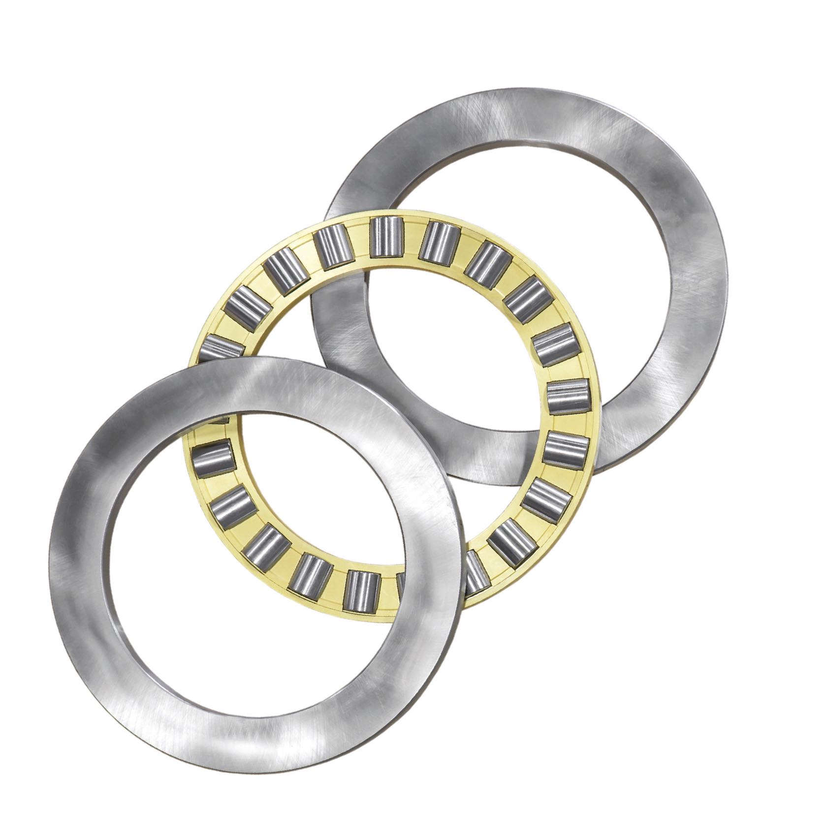
Figure 4. Thrust bearing.
Let’s review some of the variables that affect lubricant choice for various bearings, such as temperature, speed, load and system design.
The system design usually dictates whether to use grease or oil in journal and rolling element bearings. Some advantages of grease lubricated bearings are a less expensive design, less leakage from the bearing requiring less lubricant, less lubricant is squeezed out of the lubrication zone when the unit is shut down, thus, providing lubricant film almost immediately at system startup reducing wear and grease acts as a sealant to keep out dirt, dust, water and other environmental contaminants. Disadvantages of grease are it does not remove heat from the bearing and there are limits to effectiveness under high speed and load conditions. The April 2022 TLT Lubrication Fundamentals article titled “Regrease properly” discusses quantities and frequency of regreasing journal and rolling element bearings. Lubricant cleanliness and purging of the bearings also were discussed.
Journal bearing design may include grooves extending from the point of oil or grease lubricant entry to distribute the lubricant across the width of the bearing. Different groove patterns are utilized depending on the bearing application and the application of the lubricant. Some bearings only have grooving in the upper half of the bearing or away from the load carrying zone of the bearing. Other bearings may have grooving throughout the internal circumference of the bearing. However, it should be noted that grooves in the bearing load zones reduce the load carrying capacity, which is taken into consideration when sizing the bearing and recommending the right oil viscosity.
High speed, heavy loads and high temperatures in steam and gas turbines dictate the use of oil versus grease. Most of these turbines utilize journal bearings and have a lubricant circulation system to supply lubricant to the bearings. The circulating lubricant helps keep the bearings relatively cool. The lubricant circulation also removes contamination from the bearings. When the turbine is up to operating speed and temperature, the bearing lubrication is in the hydrodynamic lubrication regime or full fluid film lubrication. This was covered in the July 2022 TLT Lubrication Fundamentals article titled “The Stribeck curve.”
Oil viscosity requirements for journal bearings vary from as low as 12 centistokes (cSt) to as high as 350 cSt at operating temperature, all depending on the journal speed, or revolutions per minute (rpm), and whether the load is steady and moderate. If the bearing is heavily loaded or is expected to experience shock loads, another speed versus viscosity curve is used to determine an ideal, slightly higher viscosity than with the steady and moderate load. The recommended minimum operating temperature viscosity is then used on an ISO viscosity grade (VG) temperature versus viscosity chart to determine what ISO VG has the minimum viscosity at the system operating temperature to achieve hydrodynamic lubrication. This usually occurs when the lambda ratio reaches 3, or the lubricant film thickness is three times the combined root mean square of the surface roughness of the bearing and journal. The ISO VG calculation also can be used to determine what oil ISO VG in a grease to use in slower journal bearings where grease may be used.
Now, let’s consider the lubrication regime of turbine bearings at startup, well below the rpms required to reach hydrodynamic lubrication. Many turbine lubrication systems utilize hydrostatic lubrication to separate the journal from the bearing during the startup of the turbine providing enough oil to produce a mixed-lubrication regime before a full fluid can be established. At startup, an oil pump generates oil flow into the bottom of the bearing to the grooves in the bearing and lift the journal off the bearing surface. Once hydrodynamic lubrication is achieved the hydrostatic pump is no longer required to maintain a lubricant film, a full fluid film.
Automotive engine bearings also are lubricated via circulation system; however, they are not hydrostatically lubricated before the engine starts. The automotive bearings rely on residual engine oil in the bearing and antiwear additives to protect the bearings during startup.
Journals float on an area of lubricant film due to the conforming surface of the bearing to the journal. Rolling element bearings have a point of contact between the ball rolling elements and the raceways, and a line of contact between the rollers and raceways. In both cases, these are non-conforming surfaces and are key to developing an elastohydrodynamic (EHD) lubrication regime. The pressures exerted on the bearing races and rolling elements are in the range of 300,000 psi, which deforms the metals instantaneously and momentarily traps the oil in the contact zone. Under these pressures the oil’s viscosity also momentarily increases the oil’s viscosity exponentially to separate the rolling element from the race. EHD lubrication calculations involve surface roughness, rolling element type, temperature and speed to determine the proper ISO VG. EHD lubrication is a complex subject that we will have to address in another article.
The type of rolling element and the cage that maintains the elements positions dictate the maximum speed a bearing may run safely. Both bearing size and rpm determine the actual speed of the rolling elements of the bearing. Therefore, bearing OEMs utilize the “NDm” factor, or value, to express the maximum operating range for the bearing. The NDm factor also offers a general guide to maximum factor allowed for oil and for grease lubrication (see Table 1).
Table 1. Maximum NDm factors for lubrication
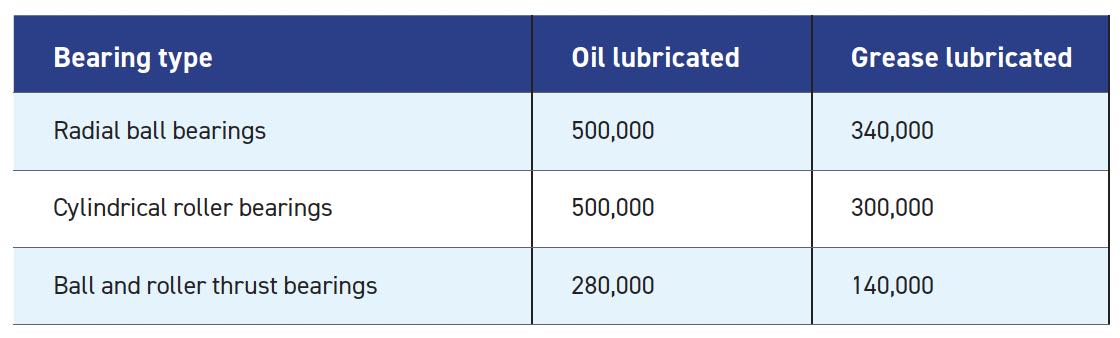
The NDm factor is a product of bearing rpms (n) times the sum of the inner race bore (d) and the outer race outside diameter (D) in millimeters, all divided by 2, or NDm = n(d + D)/2.
The DN factor, perhaps a predecessor to the NDm factor, only utilized the inner race bore in millimeters times the rpm to get the DN factor. Most rolling element bearing OEMs have stopped using the DN factor in favor of the NDm factor, because of the wide rolling element size variations. The NDm factor equation essentially takes the pitch circle, or average diameter of the bearing race diameters, times the rpms to determine the factor.
Rolling element bearings require significantly less oil than journal bearings. This is partially why greased rolling element bearings can go so long between regreasing. The rolling elements push the grease out of the way of the rolling elements just enough to not interfere with the rolling elements but not so far as to not contact each other. The rolling elements continue to swipe against the grease, wicking just enough oil to lubricate the bearing. Interestingly, high speed rolling element bearings require low oil viscosity, as expected, but they work better with a stiffer, or higher NLGI grade, grease (see the May 2022 TLT Lubrication Fundamentals article titled “Grease fundamentals: What color grease is best?”). The stiffer grease does not slump back into the path of the rolling elements, which would cause additional resistance in the bearing and overheating.
Similarly, oil baths, whether maintained via a bottle oiler, oil baths or oil circulation system, can cause extra internal friction. The oil level should only be up to midway of the bottom rolling element. This provides enough lubricant to protect the bearing but not so much as to cause interference in the rolling of the elements and overheating. More oil is not necessarily better.
Bearings are often designed to be “sacrificial” to protect more critical components of a system or machine. However, with today’s higher performing lubricants and better metallurgy, using the right lubricant and the application of it, the bearing may last the lifetime of the equipment. In fact, more bearings are “packed for life” with long-lasting lubricants, never needing relubrication. As the name implies, packed-for-life bearings are expected to last the life of the equipment.
Dan Holdmeyer is retired from Chevron Lubricants and is based in Washington, Mo. You can reach him at dan.holdmeyer@gmail.com.