Fundamentals of hydraulics: Reservoir designed to do more than hold the fluid
By Dan Holdmeyer, Contributing Editor | TLT Lubrication Fundamentals June 2023
When proper maintenance protocols are followed, a reservoir’s design ensures that the pump keeps working efficiently.
Last month we discussed hydraulic pump type designs, their limits, advantages and disadvantages. They are positive displacement pumps that generate flow, not pressure. The pump may appear to be the most critical component, but it cannot work or survive without proper design, arrangement and maintenance of other components. What are the many key components in common hydraulic systems?
Let’s first look at the reservoir that holds the system’s fluid for circulation. For industrial applications, a general rule of thumb for reservoir capacity is three times the system’s total pumping capacity. For example, in a system with two pumps, one has a 20 gallon per minute (gpm) capacity and the other a 30 gpm capacity, for a total system capacity of 50 gpm. The reservoir should then have a capacity of 50 x 3, 150 gallons. This allows the fluid three minutes of “residence” time in the reservoir to cool, release entrained air, demulsify water and drop out particulate contamination.
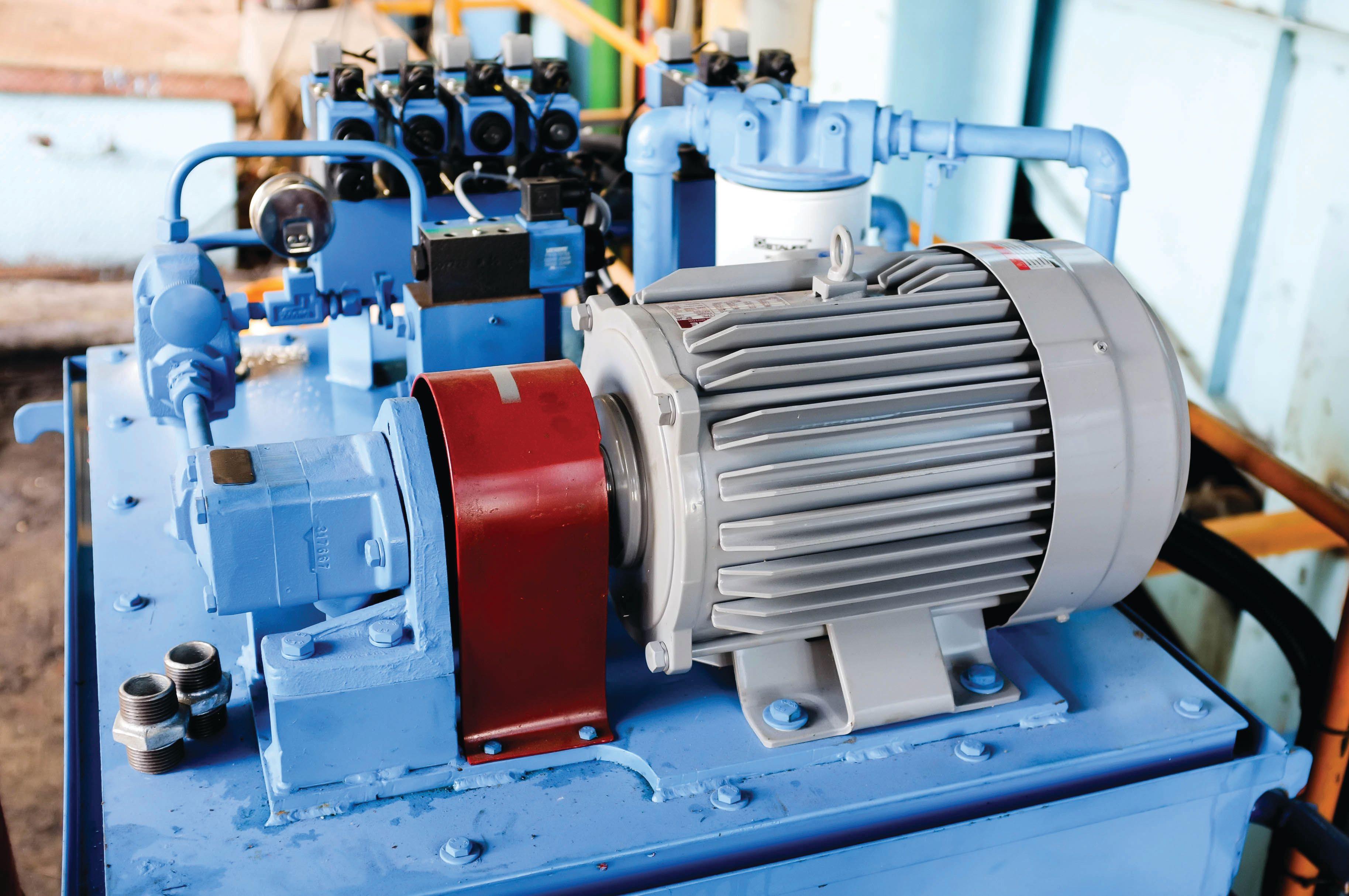
To save space and reduce weight, mobile equipment hydraulic system reservoirs are proportionately smaller and thus rely on additional oil coolers and filtration to remove heat and particulate matter, respectively (see Figure 1). To deal with water, some OEMs pressurize the reservoir to help keep out water, while others recommend dispersant additives in the oil to keep the water from agglomerating and going through the system without protection of any oil.
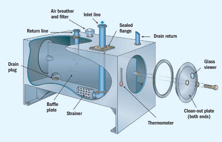
Figure 1. Hydraulic reservoir components.
Baffles are installed inside the reservoir to prevent fluid returning from system circulation going directly to pump inlet with minimal residence time. The baffles are of various designs. Some are solid forcing the fluid to flow over the top of the baffle to remove water and particulate contamination. Others may be taller, perforated or have other openings so any foam is held back from the pump inlet area.
The bottom of the reservoir is usually sloped towards a drain. The drain is not only used when a fluid change out is required but can be used to drain any water that has accumulated. It is common practice in humid or wet environments to open the reservoir drain after a period of downtime to remove water.
A cleanout cover enables wiping down a drained reservoir of sediment, wear debris and varnish when a system fluid change out is needed. This procedure is often not performed in an effort to get the system back online; however, it will likely lead to a system failure or at least erratic operation. Imagine pouring in a fresh charge of clean hydraulic fluid into a reservoir that has been in operation for years collecting dirt, wear debris and degraded oil products at the bottom of the tank. When the fluid is poured into the reservoir, all of that sediment is stirred up and suspended in the fresh fluid. When the hydraulic system is subsequently started, all that suspended sediment is drawn into the pump causing excessive wear, pumped through the system filter possibly plugging it prematurely and forced into system valves causing them to get stuck or operate erratically.
Following a pump failure, the reservoir should be drained and cleaned via the clean- out cover because a lot more wear debris will be in the system from a pump failure than from normal operations. The system filters also should be replaced following a pump failure. Again, this system cleanup is often skipped after a pump failure because an unscheduled failure has already put production behind schedule and maintenance is pressured to get the system back online as quickly as possible.
A fluid level gauge is a must on a hydraulic system reservoir. Many are clear sight gauges that also may have a thermometer to monitor reservoir fluid temperature. A single long sight gauge enables monitoring fluid level, foam formation, fluid discoloration and possibly water contamination. Some reservoirs may have multiple level gauges to see into different sections of the reservoir. Some gauge designs only indicate fluid level.
Fluid level is important for the obvious reason of needing fluid to circulate and to transfer power, but there are other reasons to keep optimum reservoir fluid levels. Piping moves returning fluid from circulation to the reservoir end below the optimum fluid level to avoid introducing additional air into the fluid. If the fluid level is low and below the return line end, air is beat into the fluid causing foam and air entrainment that may not entirely dissipate. Additional foam will impede heat radiation from the reservoir and may overflow from the reservoir causing slip and fall hazards. Air entrainment that reaches the pump inlet will likely cause aeration and erosion damage to the pump, and erratic hydraulic actuation due to the compressibility of air. (For more information on cavitation, see the February 2022 TLT Lubrication Fundamentals article title “Air entrainment, aeration, cavitation and foaming: How are they related?”)
Similarly, air is allowed to enter the pump inlet if the fluid level is low, and the fluid level does not have to expose the pump inlet to allow air to enter. A vortex forms as oil is drawn from a relatively thin layer of fluid covering the inlet and allows air to be drawn in with the fluid. Aeration and erosion damage follows.
Multiple optimum fluid levels may be appropriate for certain hydraulic systems. A hydraulic lift or elevator has a large single acting cylinder that holds large amounts of fluid when fully extended, and not so much when the lift is lowered. The optimum reservoir fluid level is different for different cylinder positions. Knowledge of the hydraulic system operation is helpful in knowing the proper fluid level to target.
Because hydraulic fluid levels fluctuate significantly, reservoirs need to be able to “breathe” air in and out to compensate for changing fluid levels. All hydraulic systems do breathe, some more than others. Even pressurized reservoirs have fluid level, and thus air head space, changes. Non- pressurized reservoirs have breathers. These breathers have particulate filters, or should have, to reduce the amount of particulate that enters the system. In humid environments, breathers should be fitted with a desiccant breather that removes particulate and moisture from the air.
Most desiccant filters change color as the desiccant reaches its moisture absorbing capacity to indicate when to change out the filter. Closer observation of this color change reveals from where the moisture is entering the system. Desiccant color change in the filter closest to the external air filter entrance indicates moisture from the environment is collecting in the filter, which is why the desiccant filter is in place. That is good. However, if the desiccant color change starts closest to where the air is being “exhaled” from the reservoir, moisture is coming from the system, possibly due to an oil cooler leak or water entering the system via a faulty seal that needs to be identified and corrected.
Another common filter in hydraulic reservoirs is a magnetic filter, which is just a magnet submerged in the fluid. The magnet collects ferrous wear debris to reduce component wear. The collected wear debris is usually quite fine and indicative of normal wear. Large metal pieces collected on the magnet indicate more catastrophic wear and potential failure.
Electric immersion heaters may be used if the hydraulic reservoir is exposed to a cold environment and needs to startup quickly. It is critical that the heater is sized properly to not prematurely oxidize the oil. A common, somewhat conservative, rule of thumb for hydraulic fluids is to not use a heater with a watt density above 10 watts per square inch. These units need to be checked periodically to keep them clean and in good operating condition.
Ideally, the reservoir has an oil sampling port for periodically pulling an oil sample for analysis. The sample port assists in pulling a representative sample consistently from the same part of the system without opening the system and exposing it to potential contamination. The fill cap usually screws tightly against a screwed in strainer. The strainer is there to prevent foreign objects from entering the system, but it also makes it difficult to grab an oil sample. Thus, a sample port is a helpful addition if the original reservoir was not designed with one.
Pump placement relative to the reservoir fluid level is another design consideration. Many pumps are mounted on top of the reservoir, which works fine if the pump inlet piping is not restricted. If the inlet piping has multiple elbows or is not equal to the inlet port in diameter, or is dented/crushed, the fluid flow to the pump is restricted. If restricted enough, the fluid pressure at the pump inlet may be lowered enough to pull air in the oil to come out of solution leading to cavitation in the pump causing excessive, premature wear. Ideally, the pump inlet is mounted below the fluid level so there is a positive head pressure pushing the fluid into the pump. This is particularly important with certain water containing fire resistant hydraulic fluids. The higher density of water requires a greater pressure drop, or a “vacuum,” at the pump inlet to raise the fluid up to a pump on top of the reservoir. Some systems use a gear pump to “prime” the primary hydraulic pump to minimize cavitation.
Many hydraulic systems have an intake screen to stop large particulate and rags from entering the pump. Intake screens require cleaning when they are plugged. That sounds obvious but is often overlooked, or not considered unless the cleanout cover is removed. A plugged intake screen also will lead to cavitation. So, if the sound like marbles or gravel flowing through the pump is heard, the inlet piping or intake screen may be the culprit. (For more information on cavitation, see the February 2022 TLT Lubrication Fundamentals article titled “Air entrainment, aeration, cavitation and foaming: How are they related?”)
A few thoughts on reservoir maintenance versus design. Always check the fluid level as we discussed. Check oil and air filters. Some are changed on a calendar basis, others have delta pressure gauges to indicate need for a change, and desiccant filters typically change their color to indicate they need to be replaced. Make certain the fill cap is in place and tight. Check the grommets and other seals around piping and removable plates to make sure they are in place and do indeed seal out contaminants. Keep dirt and debris off the reservoir to minimize the chance of contaminating the system and to allow the reservoir to radiate heat away. Part of the reservoir’s function is to remove heat from the fluid, but if the reservoir is covered in a blanket of dust and dirt, it cannot dissipate the heat effectively.
Next month we’ll delve into other hydraulic system components and maybe some of their lesser-known characteristics.
Dan Holdmeyer is retired from Chevron Lubricants and is based in Washington, Mo. You can reach him at dan.holdmeyer@gmail.com.