KEY CONCEPTS
•
Rolling element bearings in applications where they are at standstill for extended periods of time are more prone to false brinelling, and with recent supply chain constraints, it is seen as a growing type of wear.
•
A number of screening tests are available to examine lubricants, materials or coating while designing bearings and lubricants.
•
Carefully selected lubricating grease can help prevent false brinelling or extend the time until damage occurs.
False brinelling often occurs when a lubricated rolling bearing is stationary during transport either by sea or rail or if a bearing deliberately performs only very small oscillating movements.
1 STLE member Dr. Carl Hager, a tribology specialist, The Timken Co., says, “It is a common type of rolling element/raceway wear that can occur in bearings when they are oscillating/dithering/vibrating and not fully rotating. This can be associated with the application operating conditions, or something that occurs during system transport or lock down.” False brinelling wear marks are caused by micromovements associated with very low-amplitude oscillation/vibration between the rolling elements and the raceways. Hager adds: “If false brinelling is not addressed, the system will require service to replace the bearing due to excessive running vibration or end of bearing life due to raceway fatigue. Depending on the system, the wear particles may cause other issues. They can cause wear or denting on other bearings and gears that share the same lubricant or housing. If the bearing is greased and sealed, the trapped debris may cause raceway and rolling element wear. This can lead to excessive internal bearing clearance, seal wear, lubricant leakage, etc.”
This article provides an overview on the mechanism of the problem, key test methods to identify the issue and also discusses wear mitigation strategies with optimized tribological solutions as key methods to reduce false brinelling wear and further bearing damage.
Recognizing false brinelling failure
False brinelling is a form of fretting wear.
1 Hager explains, “Brinelling is the damage associated with overload of non-rotating rolling element bearings. The contact stress, at the roller/raceway interface, exceeds the yield strength or elastic limit of the materials. This causes roller spaced indents on the raceways. Fretting is small amplitude oscillation (fretting describes the motion). Fretting can be defined by oscillation amplitudes shorter than the contact length in the direction of motion. Fretting wear, wear associated with fretting motion, between rolling elements and raceways can produce roller spaced wear tracks. At first glance, the damage may look like brinelling. After further examination, it is determined that the damage is not brinelling or false brinelling.”
All definitions of false brinelling include roller spaced raceway damage. Not all definitions include fretting wear. Sometimes people add the mechanistic term “fretting corrosion.” Explaining fretting corrosion, Hager says, “Unfortunately, fretting corrosion is a term used in two different ways. First, it is often used to describe localized corrosion in regions of fretting—essentially, fretting assisted corrosion. Second, it can be used to describe fretting wear, when corrosion or chemically assisted wear is a primary damage mechanism.” R. B. Waterhouse published the book “Fretting Corrosion” in 1975. His book included the following definition: “fretting corrosion—a form of fretting in which chemical reaction predominates.”
2 Hager continues, “For metallic material contacts, the wear damage often starts via an adhesive mechanism. The produced wear debris may oxidize. Trapped abrasive oxide particles can accelerate wear. If the debris or surfaces oxidize, people will often identify it as fretting corrosion. False brinelling is fretting wear damage between rolling elements and raceways, regardless of severity, wear mode or debris/surface oxidation/corrosion.”
Rachel Januszewski, a research assistant, Imperial College London, UK, explains that false brinelling and fretting corrosion are both fretting types of surface damage. Fretting-type damage occurs because of small amplitude motion between surfaces, the motion usually being due to external vibrations. False brinelling is the specific name given to fretting in rolling element bearings, and fretting corrosion is often used when the damaged contact is unlubricated. In steel contacts, red oxidized ferrous debris is often produced. In unlubricated fretting corrosion, the appearance of the debris is often described as “cocoa,” and in lubricated false brinelling, the debris mixed with lubricant sometimes leads to the bearings being described to be “bleeding.” False brinelling results in craters that are evenly spaced around the rings and have a relatively polished appearance from the wear that distinguishes them from brinelling craters that are formed by heavy impacts, Januszewski says.
STLE member Dr. Johan Leckner, a professor in Lubricant Design at KTH Royal Institute of Technology, and a group technical manager, Axel Christiernsson International AB, concurs that false brinelling and fretting corrosion can be difficult to differentiate. He explains: False brinelling occurs in a lubricated contact under mixed lubricating conditions causing the formation of wear particles mainly consisting of magnetite (Fe
3O
4). In an unlubricated contact, the wear will instead be in the form of hematite Fe
2O
3, which is more abrasive and will cause fretting corrosion. In a reality, the lubricant can be pushed out of the contact leading to roller/raceway fretting corrosion. It is, therefore, often hard to differentiate the two, says Leckner.
STLE member Dr. Markus Grebe, a scientific director of the Competence Center for Tribology, Mannheim University of Applied Sciences, Germany, says that there also are other failure types which can be connected or mistaken for false brinelling. He explains: As the name false brinelling suggests, the trough-shaped marks can be mistaken for plastic indentations, e.g., due to an assembly mistake or an overload. In the uncleaned state, however, tribologically induced false brinelling damage shows a dark coloration (reddish brown to black) of the grease as a result of the entrained particles. The shape of the depressions also is not quite as precise as in the case of a plastic impression. In addition, with plastic deformation, bulges usually form at the edge of the trough due to the displaced material, Grebe adds. He continues: Standstill marks can often be seen in the inner adhesion zone and the damage zone around it (micro-slip area)
(see Figure 1).3 In this zone, wear phenomena known from fretting (tribo-oxidation, local adhesion, disruption) dominate. Standstill marks also can occur as a result of classic contact corrosion. In this case, however, there is no adhesion zone in the center, no tribologically induced signs of wear and often further traces of corrosion in other areas, says Grebe.
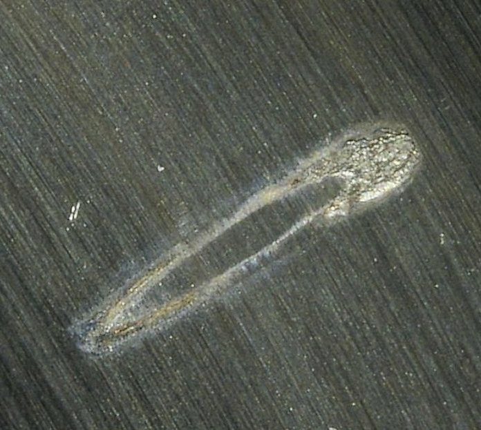
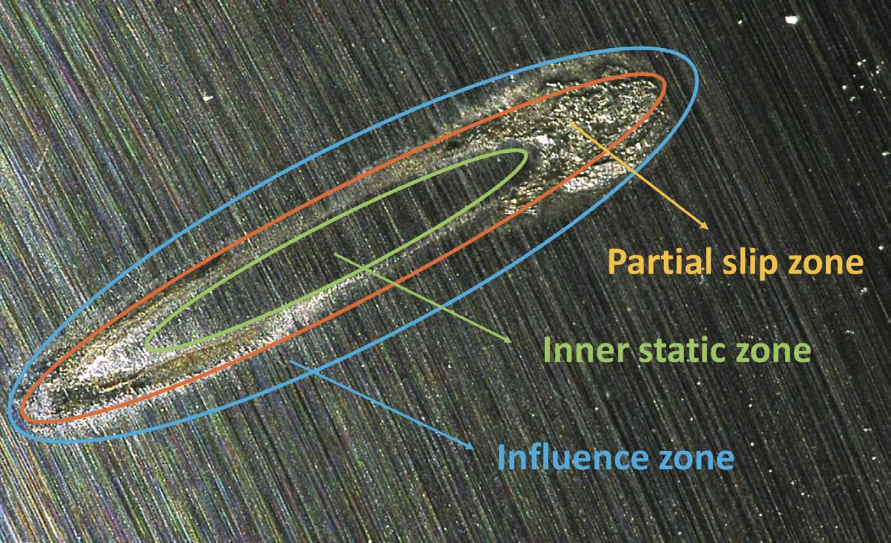 Figure 1. Distinctive areas of a standstill mark. Figure courtesy of Mannheim University of Applied Sciences.
STLE member Jacob Bonta, a product development chemist, Valvoline Global Operations, adds that when false brinelling occurs in bearings, it can set off a chain of other damage modes that ultimately lead to failure. False brinelling causes grooves to form in races that change the surface roughness. When a bearing is operated after this damage occurs, the rolling elements pass through these areas of varied roughness causing excess vibration and generating wear debris. This debris further accelerates the degradation of the bearing, rapidly increasing the wear rate of the components. These damage modes are self-enhancing and only accelerate with operation time, ultimately leading to premature failure, says Bonta.
Besides what is previously mentioned, electrical damage also can be difficult to distinguish from false brinelling. Electrical damage results in a “corrugation” or “fluting” effect to rolling surfaces, which can sometimes be similar to false brinelling; however, electrical fluting also will often show signs of discoloration from surface burning.
How false brinelling occurs
Grebe states that when analyzing why false brinelling occurs and the cause mechanisms, the first step is to clearly distinguish between two cases of damage: classical false brinelling, in which deep depressions form (from which the name also was derived), and so-called standstill marks, in which there is a change in the surfaces in contact (predominantly tribooxidation, adhesion, disruption) but in which no depressions will form.
3 The decisive factor here is the ratio of the length of the rolling element’s rolling motion (x) to the width of the Hertzian contact surface (2b). With x/2b ratios > 1, the contact point is opened cyclically. For ratios smaller than 1, at least part of the contact area always remains closed. Within the contact area, a stationary stick zone and an area with partial micro-sliding is formed. Figure 2 illustrates different scenarios.
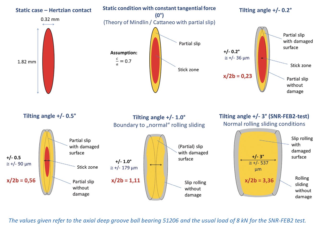 Figure 2. Several scenarios of false brinelling occurrence. Figure courtesy of Mannheim University of Applied Science.
Grebe further notes: “The damage mechanisms also can be derived from these kinematic and contact mechanical boundary conditions. If the contact point is opened, the viscosity and the reflow behavior play a decisive role. If the lubricant manages to relubricate the friction point in the short time of opening the contact, no damage usually occurs. If it fails to do so, there is insufficient lubrication, and the typical signs of wear occur. The resulting wear particles quickly lead to a thickening of the remaining grease and, thus, further reduce the flow so that the damage then quickly escalates.” He continues: “With x/2b ratios <1, the whole thing is much more complicated. Here, the lubricant can hardly flow into the closed contact zone (only via micro-roughness and microcapillary forces). As a result, the f low behavior plays a lesser role. Instead, the “lubrication behavior” plays a decisive role. Polar lubricants that show a good natural lubricating effect, such as esters or polyalkylene glycols (PAGs), often perform better. Ultimately, no lubricant can completely prevent damage under these critical conditions; at some point even the last protective molecules will be worn out. In our experience, only thin layers such as diamond-like carbon (DLC) or tungsten carbide/carbon (WC/C) or regular opening of the contact through larger oscillating movements or rotation can help in the long term.”
Januszewski concurs that metallurgy also can be used to reduce brinelling damage by selecting hard materials that also have good adhesion resistance. From her experience, DLC coatings also have been found very effective against false brinelling damage.
Grebe continues, “Basically, problems occur much more frequently with grease lubrication than with oil lubrication, as the mobility of a grease is limited to a desired extent and, thus, the risk of deficient lubrication phenomena is higher.” He adds, “Both of the previously mentioned operating conditions occur, for example, in the blade bearings of wind turbines—the very small pivoting movements in the case of a vibration load and the larger ones in the case of deliberate blade displacements. Vibration loads usually lead to standstill marks. All rolling bearings are at risk here that are exposed to significant vibrations and stand still for long periods of time, such as in construction machinery, pumps but also in drives and gearboxes of electric vehicles. Classic false brinelling damage is often found, for example, in greaselubricated systems that perform small positioning tasks.”
Januszewski adds that the only way to prevent rather than alleviate false brinelling is by mechanical design to inhibit vibrations or to isolate the bearings from the source. The damage can be reduced under false brinelling conditions by ensuring that bearing elements do not rock in the same position for long periods of time, e.g., by using an auxiliary mechanism to continuously rotate machine parts in a slow, steady motion to distribute the lubricant and the wear,
4 Januszewski states.
Furthermore, there are some underlying mechanisms of false brinelling, and there also are ways to prevent them, says Januszewski. She explains, “An important part of the false brinelling mechanism is lubricant being pushed out of the rubbing area by a combination of the small amplitude motion between the surfaces and the high local pressure. The small amplitude of the motion can neither fully entrain lubricant nor push wear particles and reaction products out of the contact area. These lead to severe adhesive and abrasive wear conditions.” Per Januszewski, the only way to fully prevent false brinelling is to stop the motion between the surfaces by preventing or isolating the contact from vibrations. If this is not practical, then false brinelling damage can be reduced by changing the external loadings or geometry to reduce stresses or by selecting a suitable lubricant with surface preparation and contact conditions that allow for it to easily penetrate the contact.
Test methods for false brinelling palliatives
There are few tests which can help with evaluation of tribological properties of greases to prevent false brinelling. Januszewski refers to ASTM D4170, the industry standard for quantifying the false brinelling performance of greases. ASTM D4170 is named “Standard Test Method for Fretting Wear Protection by Lubricating Greases.” The test was originally developed to predict the fretting performance of greases in wheel bearings of passenger cars shipped long distances. The specified tester operates with two ball thrust bearings, lubricated with the test grease, oscillating at a prescribed frequency and load
(see Figure 3). Fretting wear is determined by the change in the mass of the bearing races.
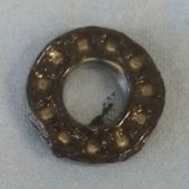
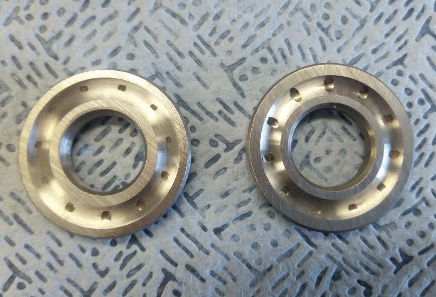 Figure 3. The fretting wear test machine specimens: a.) discolored grease after testing, b.) test using low viscosity grease and c.) test using high viscosity grease. Figure courtesy of Imperial College of London.
“Custom-built rigs have been used for study as well as simple bench top rigs such as the high frequency reciprocating rig (HFRR) and SRV, which stands for Schwingung (oscillating), Reibung (friction) and Verschleiß (wear),” Januszewski adds.
Bonta explains that false brinelling tends to occur in bearings that spend time under idle conditions where they experience vibrations, such as during the shipping of machinery. False brinelling also can occur in bearings that only move slightly through their rotational range during use, such as steering components or oscillating devices. Thus, a test seeking to determine the utility of a grease for protecting against this damage mode should attempt to emulate the conditions that cause it as closely as possible—generally, Bonta says, this means moderate to high contact stresses, low temperatures and small amplitude oscillations. Within the industrial testing techniques, there are a few that can be useful for evaluation of grease performance under these conditions. As with Januszewski, Bonta also advises on a use of the ASTM D4170 test. Although, Bonta adds, this method has suffered significant repeatability issues recently, however, due to problems related to the quality of the thrust bearings used in the test. He adds that the ASTM D7594 fretting wear test performed on the SRV is a more recent evaluation developed for greases and has been shown to be useful for understanding protective qualities under these conditions. There are numerous other modified and non-standard techniques employed to attempt to emulate the conditions that lead to this wear type in order to best understand how to avoid it, Bonta says.
Grebe gives more details on ASTM D4170. He explains, “In order to simulate false brinelling damage or standstill marks in the laboratory, it is important to correctly reproduce the real x/2b ratios in the laboratory. The so-called Fafnir Fretting Test according to ASTM D4170 runs with an oscillating angle of +/-6 degrees, which means an x/2b ratio of about 5.5. The SNR-FEB2 test
(see Figure 4), which is mainly known in Europe, runs with +/-3 degrees, which means an x/2b ratio of 3.4. Standstill marks, for example, can be mapped with a laboratory test developed at the Competence Centre for Tribology in Mannheim, where the x/2b ratio is about 0.6. Per Grebe, another test used is a ripple test of the Department of Process Metallurgy and Metal Recycling (IME) of RWTH Aachen University, which is required by wind turbine manufacturers, and also belongs to the category of standstill tests. There, the micro-sliding movements in the contact point result from the elastic deformations of the balls and raceways due to the alternating normal force load in a hydraulic pulsator test rig. At this point, it also must be pointed out that the test proposed as a replacement for the Fafnir test on the SRV test rig in a ball/plate configuration is a pure sliding friction test (without rolling motion). “This is therefore more of a classic fretting test, which, in my opinion, can only relatively poorly represent the conditions in a rolling bearing,” says Grebe. Lubricants can help prevent false brinelling.
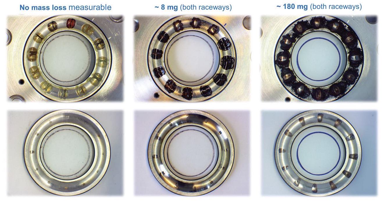 Figure 4. Examplaric mass losses in the SNR-FEB2 test. Figure courtesy of Mannheim University of Applied Sciences.
Leckner concurs that oscillating bearing tests like the Fafnir Fretting Test (ASTM D4170) or SNR-FEB 2 are full bearing tests and are useful, but he also points out that they are fixed to one test condition (oscillation angle, frequency or load), which might not reflect the conditions in a real application. Therefore, he also suggests that in order to rely on a test for protection against false brinelling, a full bearing test that reflects the conditions (contact pressure, motion and temperature) of the application in mind is needed.
In addition, Leckner continues, from his experience and research, most of ball-on-disk experiments do not have any correlation to false brinelling damages in bearings, so he would caution against relying too much on these type of tests.
5
Lastly, there are computer simulations used to screen for bearing performance, but they are not ideal to predict lubricant performance in a bearing, says Grebe. He explains, “Computer simulation is a good way to simulate micro-sliding in contact as a function of geometric conditions, for example. The sliding paths and the energy input can be calculated. However, it is necessary to determine static and dynamic friction values. It is therefore not possible to calculate the effect of lubricants or to predict their influence. In addition, the flow into the contact zone is not yet taken into account, especially in the case of standstill markings.”
Role of lubricants in false brinelling prevention
Lubricants can help prevent false brinelling. Januszewski says, “Lubricants that can access the rubbing area help to mitigate false brinelling damage by providing a separating layer between the surfaces.” Many rolling element bearings that suffer from false brinelling are designed to prevent against other damage types. For example, transported vehicles only have their bearings stationary, and subjected to vibrations, during this period. The viscosity selected will normally be higher for running under “usual” conditions than the low viscosity needed for reflow and resupply of the lubricant to the contact area to reduce false brinelling damage. Additionally, most bearings are grease lubricated, which can reduce the ability of the lubricant to flow and replenish the contact.
Grebe agrees that in principle, it is possible to prevent false brinelling with a lubricant, good ref low behavior and the lowest possible base oil viscosity, which are favorable. However, care must be taken that this does not lead to other problems in normal operation (frequent relubrication intervals, problems at high temperatures), he says. Grebe continues that for standstill marks, the lubricant must be able to form a separating film in the closed contact for as long as possible. Solid lubricants, polar base oils and also physically effective friction modifiers help here for a certain time. Basically, it is very difficult to predict whether a lubricant can prevent standstill marks or not. So far, it is still not clear which influencing factors and interactions dominate, Grebe adds.
According to Bonta, a careful selection of lubricant components also plays a critical role in lubricant performance in applications. For applications that are susceptible to false brinelling, formulation choices can be made to help minimize or prevent this damage mode from occurring. As mentioned earlier, in false brinelling, bearings are usually exposed to vibrations under stationary or small oscillatory conditions. Bonta says, “One factor to keep in mind is the lack of full rotation to distribute grease evenly across the elements of the bearing, which can lead to oil film loss in the contact zone. Using a lower base oil viscosity or softer consistency grease can help to alleviate this issue but may be limited in its effectiveness. The major factor in preventing this damage mode is to ensure proper additive selection. There are a vast number of tribologically active chemistries available to provide enhanced protection to greased components, but many are not suitable to prevent false brinelling. Most additives provide protection by chemically reacting with the bearing surfaces to form a barrier film between moving components, which helps prevent wear between contacts. These chemical reactions require a certain level of energy be present in a system in order for them to proceed and form protective films similar to the diagram shown in Figure 5. This energy is mostly supplied during the operation of bearings in the form of thermal energy. Due to the low energy conditions present in the system that experience false brinelling, many additives do not achieve sufficient energy to overcome their activation barrier and, thus, are not suitable to prevent this issue.”
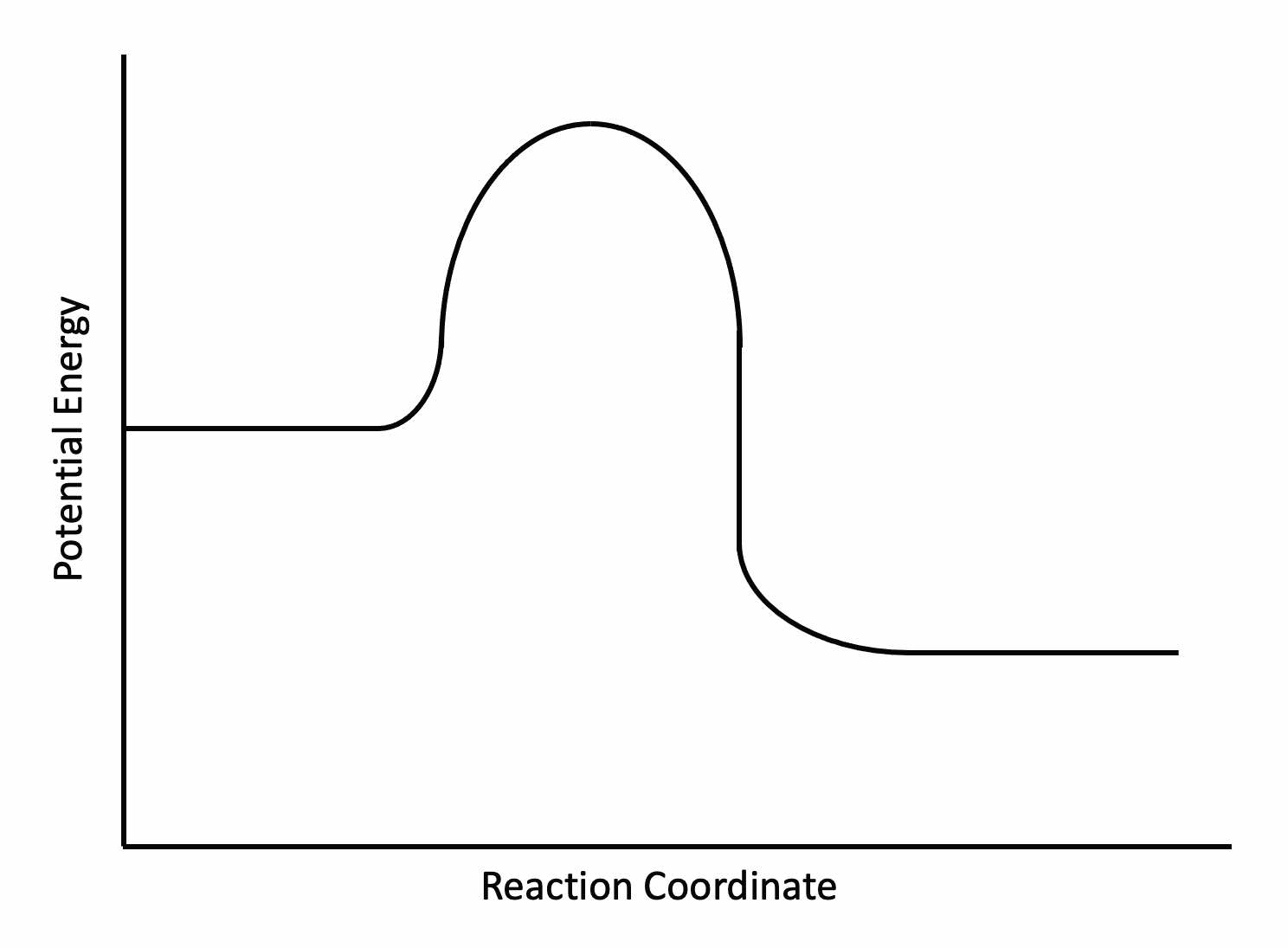 Figure 5. Activation energy chart for tribofilm formation. Figure courtesy of Valvoline Global Operations.
Bonta continues, “By selecting tribologically active components that require very little energy to react, or that work through non-reactive modes, greases that are protective against false brinelling can be designed.”
Januszewski agrees: “Additives can be very successful at reducing the damage. In order to mitigate against false brinelling damage, the additive tribofilms need to be able to survive the imposed oscillating conditions and form very quickly before significant damage takes place. Traditional antiwear additives such as zinc dithiophosphate (ZDDP) can be effective against false brinelling, and some friction modifiers such as organic friction modifiers (OFMs) are able to reduce the wear under the imposed boundary conditions.”
Leckner says that it all comes down to having a lubricant that can relubricate the oscillating contact; the thickener type and additives are unimportant if this is not achieved. Therefore, the motion (more specifically, the frequency and the ratio between the movement of the rolling element and the size of the Hertzian contact area) needs to be matched with the lubricant. For larger motions and/or lower frequencies, it is possible to use a somewhat higher oil viscosity and a medium high oil release. For high frequencies and/or smaller motions, a low base oil viscosity promoting high oil release is essential to relubricate the contact
6,7 (see Figure 6).
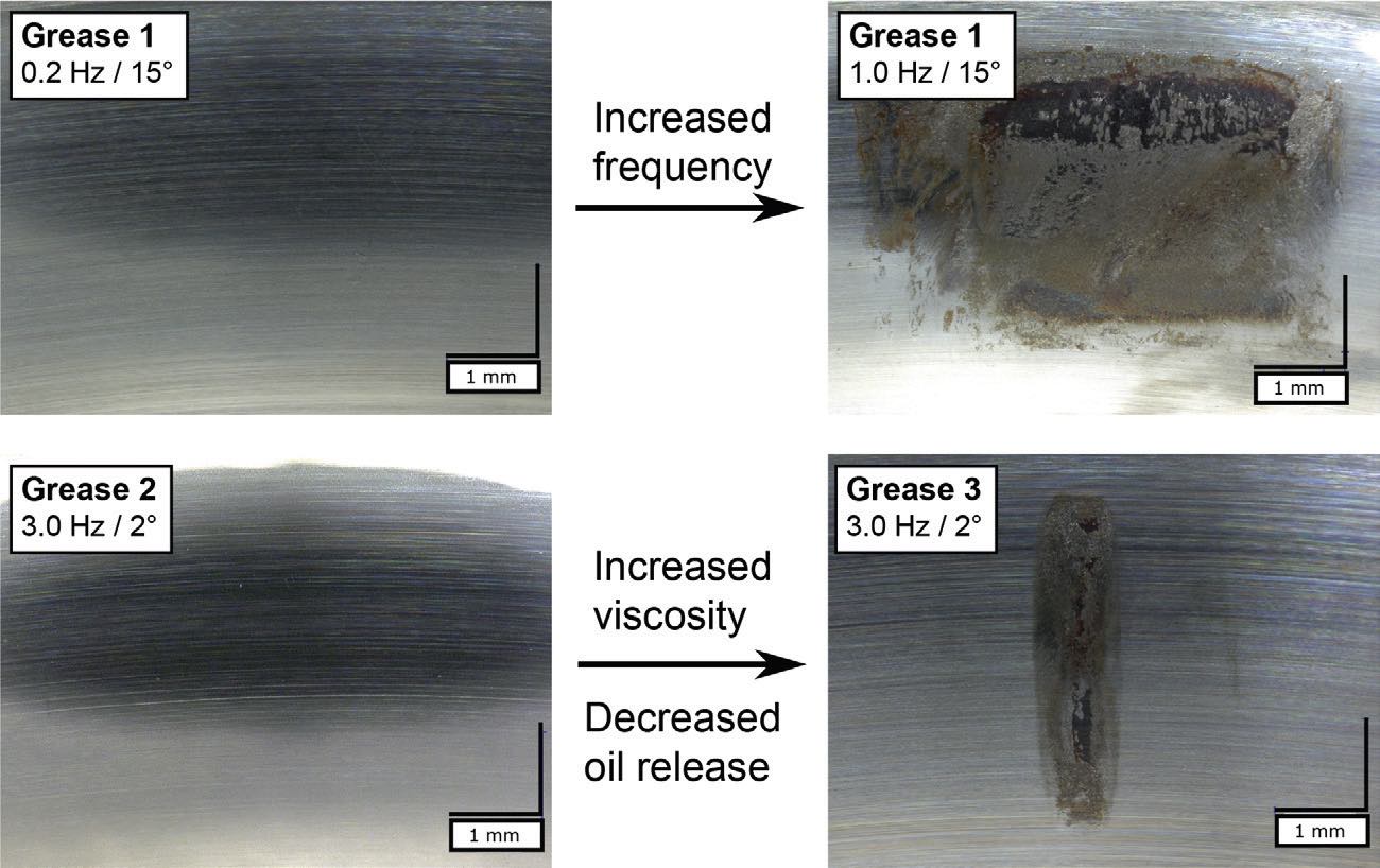
Figure 6. Fretting in oscillating angular contact ball bearings (7208) for three greases with the same thickener and base oil type. Row 1: The effect of only increasing the oscillation frequency at larger x/2b ratios. Row 2: The result of changing from a lower base oil viscosity grease to a higher base oil viscosity grease at low x/2b ratios. Figure courtesy of Sebastian Wandel, Leibniz University Hannover.
Lubricating grease-related strategies to mitigate false brinelling
According to Leckner, unfortunately there is no silver bullet to mitigate false brinelling with a lubricant, but there are greases that manage to prevent damages better than others, e.g., greases with low base oil viscosities and high bleeding rates show the least wear, since the bleed oil can reflow in the contact zone
3 in some applications. In general, for a good protection, the lubricant properties must be matched to the oscillation motion.
Leckner explains: “For example, in a wind turbine pitch bearings application, the mode of operation (the active pitch control) imposes an oscillating motion on the bearing. This bearing will never experience full rotations, only smaller and larger oscillating motions. For this, an optimal grease is designed to protect against fretting. Here oil release is the most important parameter; both additives and thickener are secondary. If oil is not reaching the contact, the additives and the thickener will not reach the contact either.”
He continues: “There also are applications that are designed to operate in full rotations but have vibrations imposed on them from some external force when at standstill (e.g., transportation damages, standstill markings, etc.). In this case the grease design cannot be all about fretting; it needs to be designed around the main purpose of the bearing. The additives and thickener system are the primary focus as they have to support the normal mode of operation of the bearing, but also there is a need to add fretting protection. The optimal grease would be designed for the application but should be able to provide rather high oil release. Thus, additives and the thickener are more important as during the normal operation mode, tribofilms can be built that have a potential to protect against fretting at standstill. Great performance can be achieved with numerous additives and thickener systems; it is all about tuning the grease specifically for the application.”
Bonta states, “Careful formulation of greases can help prevent false brinelling from occurring. Critical to this formulation is an understanding of the environmental and operating conditions of the bearings as well as key parameters associated with the bearing geometry and metallurgy chosen. With this information, laboratory testing can be done to emulate these conditions and inform the choice of materials used in the grease.”
Januszewski adds that a carefully selected grease thickener and a base oil viscosity also can play significant role: “Greases with polyurea and calcium sulphonate thickeners are both effective in laboratory tests, as are lubricants with low base oil viscosity,” she says. “The consistency and base oil bleed of a grease also influence the wear with those most able to allow lubricant flow being more effective,” Januszewski adds.
Looking into the future, there may be solutions based on surface-active ionic liquids, if they can be delivered to the contact, says Leckner.
Lubricant analysis after false brinelling occurs
Bonta says that it can be very difficult to determine false brinelling damage in bearings through lubricant testing. The symptoms of this damage mode can be excess vibration or heat generation within the bearings, but it quickly leads to a complex set of contributors from wear debris and lubricant contamination that lead to failure. Elemental analysis of lubricants can indicate excess levels of wear metals present, which can suggest a high wear rate. Particle analysis also may detect wear debris, again suggestive of the damage.
Leckner explains: “The damage marks on the bearing race are so characteristic that normally there is no need to analyze the lubricant to understand what is going on. However, looking for iron in the sample of a lubricant will help—mainly magnetite in the early onset of fretting corrosion and later also the presence of hematite when the damages have progressed to fretting corrosion.”
In-application related practices to reduce false brinelling
Bonta says that beyond the choice of a grease to help mitigate the occurrence of false brinelling, there are several practices which can be applied to reduce the occurrence. For example, running in of bearings before shipping can help evenly distribute greases and form protective films. Also, the use of bearing locks during shipping can prevent the small oscillations than can lead to the damage. The condition is often observed in units that spend significant time in an idle or standby state. Regular operation of equipment for a short period to ensure consistent lubricant distribution can be helpful. Another common environment that can cause this damage mode is in paired units in close proximity where one is used as a backup, such as in power generation applications. The operating unit causes vibration in the standby unit, which can lead to false brinelling and ultimately failure after operation. Separation of paired units or mechanical isolation can help prevent the damage from occurring, Bonta says.
Leckner suggests relubricating the contact by rotating the bearing every now and then. It does not even have to be a full rotation; a larger motion also will do the trick.
Grebe says that a skilled machine operator can hear that false brinelling has occurred and can prevent further damage to the unit. He explains: “Deep hollows, as they occur in false brinelling, lead to significant vibrations when rolling over. When turning slowly, one notices detent positions. Standstill marks can only be recognized at an advanced stage by an increase in vibrations and noise during normal operation. However, a clear assessment is only possible during disassembly and this only if the initial damage features have not yet been covered by consequential damage (e.g., abrasion or pitting). Although these standstill markings appear to be quite inconspicuous, they have been shown to significantly reduce bearing life.
Summary
It is usually easy to identify bearing damage but often difficult to prevent it or to determine the cause. As discussed previously, in many cases, bearing damage may be due to a combination of causes. Many times, a complete investigation is required of mounting, installation and related components. According to industry experts that shared their knowledge in this article, there are multiple strategies available to prevent false brinelling. Unfortunately, as discussed, none of the strategies are perfect. With recent supply chain constraints, false brinelling occurs more often than ever before; bearings within finished products (machinery, generators, etc.) are shipped around the world and multiple times re-routed or caught in between destinations and/or are waiting on the final assembly in warehouses. Future studies will hopefully look into the problem from a more holistic approach.
REFERENCES
1.
Lin, C.L., Fallahnezhad, K., Brinji, O. and Meehan, P.A. (2022), “Mitigation of false brinelling in a roller bearing: A case study of four types of greases,”
Tribology Letters, 70 (1), p. 22.
2.
Waterhouse, R.B. (1975),
Fretting Corrosion, Pergamon Press, Oxford.
3.
Grebe, M., Molter, J., Schwack, F. and Pol, G.l. (December 2018), “Damage mechanisms in pivoting rolling bearings and their differentiation and simulation,”
Bearing World Journal, 3, VDMA-Verlag, Print ISSN 2513-1753, Peer-Reviewed.
4.
Grebe, M. (2021), “Influence of vibration induced standstill marks (fretting) on bearings of e-drives,” 2021 STLE Virtual Annual Meeting & Exhibition.
5.
Schwack, F., Bader, N., Leckner, J., Demaille, C. and Poll, G. (2020), “A study of grease lubricants under wind turbine pitch bearing conditions,”
Wear, 454, 203335.
6.
Wandel, S., Bader, N., Schwack, F., Glodowski, J., Lehnhardt, B. and Poll, G. (2022), “Starvation and relubrication mechanisms in grease lubricated oscillating bearings,”
Tribology International, 165, 107276.
7.
Wandel, S., Bader, N., Glodowski, J., Lehnhardt, B., Leckner, J., Schwack, F. and Poll, G. (2022), “Starvation and re-lubrication in oscillating bearings: Influence of grease parameters,”
Tribology Letters, 70 (4), 114.
Dr. Yulia Sosa is a freelance writer based in Peachtree City, Ga. You can contact her at dr.yulia.sosa@gmail.com.