Fundamentals of hydraulics: Pascal’s principle and pump designs
By Dan Holdmeyer, Contributing Editor | TLT Lubrication Fundamentals May 2023
Pump types vary in efficiency, resistance to contamination, pressure limits and other factors, but they all work according to the same principle.
Hydraulic systems transmit power via fluid to perform specific work. Water was used as the hydraulic fluid long before any oil. Oil is nearly universally used today due to its wear and corrosion protection.
A basic hydraulic system has a reservoir to hold the fluid, a power source usually in the form of a pump, valves to control flow and a linear or rotary actuator to perform specific work. There are many additional components to the typical hydraulic system that we will also discuss.
A hydraulic jack represents the simplest form of a hydraulic system. A lever is attached to a small piston in a cylinder to draw the fluid from the internal reservoir through a check valve and then to move the fluid past another check valve into a larger cylinder and piston. Finally, a control valve can be opened to allow the fluid to return to the reservoir. The small piston and cylinder driven by the lever action are the pump in the hydraulic jack. The larger cylinder and piston are the linear actuator that lifts the heavy object.
The jack capitalizes on Pascal’s principle and formula. Basically, part of Pascal’s principle is that a liquid-filled, enclosed container will exert pressure equally to all parts of the container. The formula is Force (F) equals Pressure (P) times Area (A), F = P x A or P = F/A. Thus, the fluid pressure in the small cylinder of the jack mentioned previously, depicted in Figure 1, is equal to the pressure in the large cylinder.
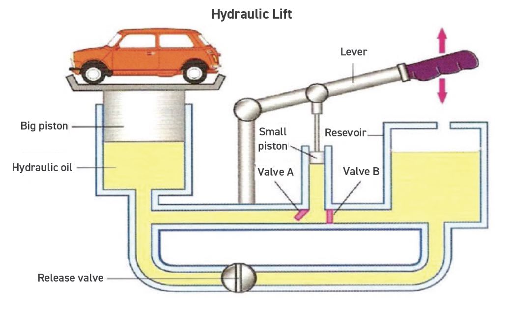
Figure 1. Application of Pascal’s principle.
Since, according to Pascal’s principle, the pressure applied to the small piston surface area (F1/A1) equals the pressure applied to the larger piston surface (F2/A2) and because the larger piston has a larger surface area, the force on the piston must increase proportionately. If the lever’s piston has a 1 square inch of surface area and a force of 20 pounds applied, the pressure in the system would be 20 psi (P = F1/A1). If the larger piston has a surface area of 100 square inches (100 times the size of the small piston), the force on the large piston would be 100 times that of the force on the small piston, 2,000 psi. Or, using Pascal’s formula of F = P x A, the pressure is 20 psi, and the large piston surface area is 100 square inches, so 20 psi (P) times 100 square inches (A) equals 2,000 pounds. This force multiplying effect of hydraulics enables moving large objects with relatively little inputted force. The “cost” for this multiplying effect is the multiple small piston cycles required to move the large piston any distance.
More complex hydraulic systems utilize rotary pumps to convert mechanical energy, typically from an engine or electric motor to hydraulic energy. The pump generates hydraulic energy by creating flow of the hydraulic fluid. Positive displacement pumps are used in hydraulic systems. “Non-positive” displacement pumps, or centrifugal pumps, simply cannot maintain the pressures required of hydraulic systems. The pump does not generate the pressure. It only generates fluid flow.
Positive displacement pumps deliver a predetermined fluid volume for each revolution of the pump. The principle involves sealed chambers in the pumps that increase in volume at the inlet side and decrease in volume at the outlet side of the pump. The outlet side of the pump may sometimes be called the pressure side; however, the pump does not generate the pressure. It only generates fluid flow.
Pressure in the hydraulic system is generated by the load, or resistance of the system. The hydraulic fluid is relatively incompressible and, thus, as more fluid is pushed into the confined space of the hydraulic system, the pressure rises to increase the force exerted on the system actuator forcing it to work. In the hydraulic jack example previously mentioned, the actuator work was the lifting of a heavy object like a car.
Hydraulic pump specifications do list a maximum pump pressure, but that is the pressure above which the pump will fail. If the force to lift the heavy object requires pressure greater than the pump pressure rating, the mechanical energy driver of the pump will likely continue driving the pump and break it in a catastrophic manner. Similarly, the hydraulic system hoses and piping have maximum pressure specifications above which they will burst. In fact, all the system components have a maximum pressure rating.
A pressure relief valve is a critical safety device in hydraulic systems. The relief valve is placed downstream from the hydraulic pump and upstream from the rest of the system. It is set to approximately 150 psi below the lowest pressure rating of all the system components. The relief valve opens at the pressure setting and returns the fluid to the reservoir. The energy in the high pressure fluid is converted to heat when the fluid is “dumped” back to the reservoir at atmospheric pressure without doing any work. Continued “dumping” of the hydraulic fluid energy through the relief valve will cause excessive heat in the system that will shorten oil life and potentially deteriorate system seals and hoses. Therefore, other methods are preferred to maintain the proper pressure but not go beyond the pressure rating of any system components, that we’ll discuss later.
The most common positive displacement pump designs used in hydraulic systems are categorized as gear, vane and piston pumps. Gear pumps are the simplest and, thus, the lowest cost to build relative to vane and piston pumps. The gear pump also has a lower efficiency and pressure limit relative to vane and piston pumps. All hydraulic systems are susceptible to hydraulic fluid contamination, but the gear pump has the best resistance to contamination. Gear pumps also are more tolerant of higher vacuum pressures at the pump inlet compared to vane and piston pumps. Generally, gear pumps are relatively inexpensive and, thus, are more economical to replace then repair the pump. They are commonly used where constant flow and pressure are needed in dirty environments such as mobile equipment.
Figure 2 shows the flow of fluid through the gear pump, between the gear teeth and pump housing, away from the meshing of the teeth. The gear teeth spacing against the housing create sealed chambers to transport the fluid from the inlet to the outlet. The re-meshing of the gear teeth collapses the size of the sealed chambers forcing the fluid out of the pump.
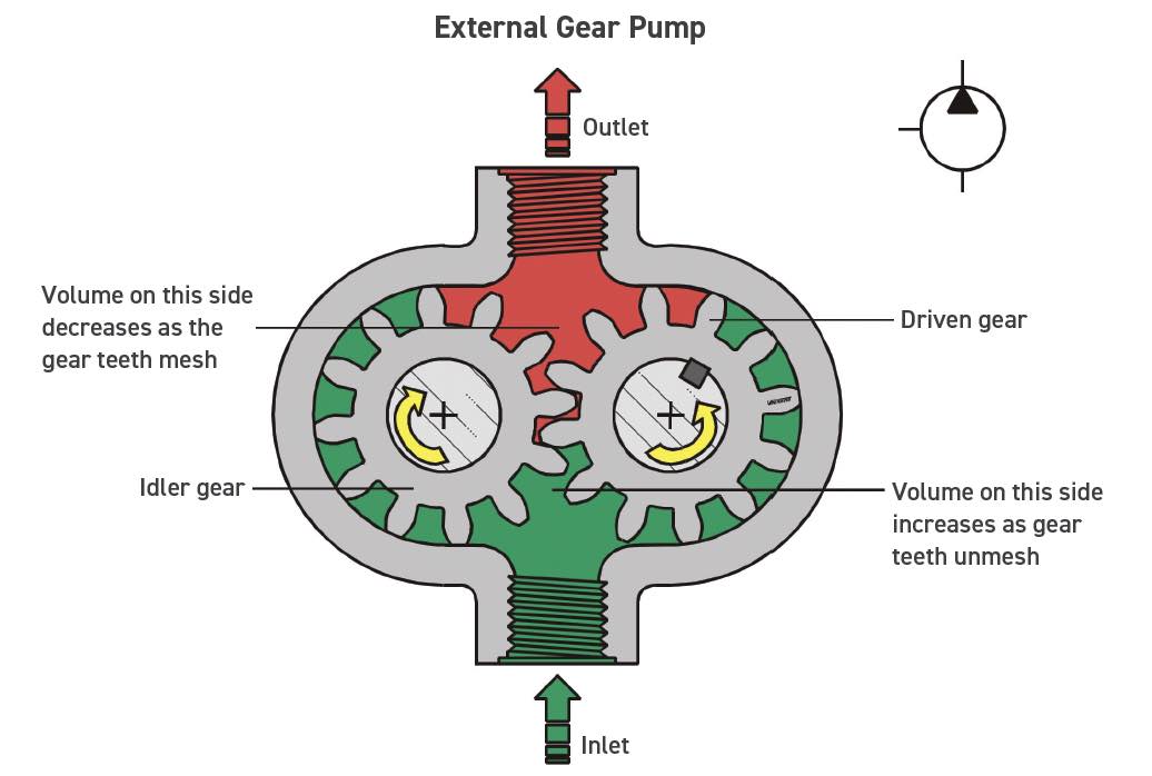
Figure 2. Gear pump.
Figure 3 shows a simple vane pump. It basically contains a rotor offset inside of the pump chamber or ring. As the rotor rotates, vanes slide in and out in slots of the rotor to create sealed compartments that expand in volume at the pump inlet and diminish in volume as they approach the pump outlet pushing the fluid into the pressurized side of the pump.
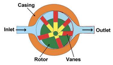
Figure 3. Simple vane pump diagram.
Higher pressure vane pumps have an oval ring with the rotor centered in the chamber. This allows for the higher pressure of the outlet ports to be opposite each other, thus balancing the load on the rotor shaft bearings. This diminishes the need for oversized bearings to handle the load. These pumps are called balanced vane pumps.
Vane pumps can have higher allowable pressures and better efficiency compared to gear pumps. The vane pump is more susceptible to damage due to fluid contamination. However, to reduce the cost and difficulty of repairing worn pumps, many designs keep the rotor, vanes and ring together as a cartridge that can easily be removed and replaced as a unit without having to buy a complete pump. Vane pumps are common in industrial applications because of their relatively quiet operation and ease of repair.
Some vane pumps are variable volume pumps that, as the name implies, can deliver various volumes of fluid into the system per revolution. It is still a positive displacement pump, but the sealed chambers within the pump can be varied to deliver variable volumes per revolution. Variable volume vane pumps are not very common.
Piston pumps, however, are often preferred for variable volume pump applications. Figure 4 depicts the basic design of an axial variable piston pump. The pistons are parallel to each other and attached to the swash plate. The angle of the swash plate, relative to pump shaft or axis, dictates the stroke distance of the pistons in the cylinder block. When the swash plate is perpendicular to the axis, the pistons simply rotate in the cylinder block without pumping any fluid. As the angle of the swash plate increases, the piston stroke distances increase, and the volume of fluid per rotation increases proportionately (see Figure 5).
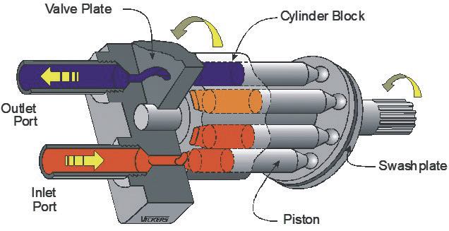
Figure 4. Variable volume axial piston pump.
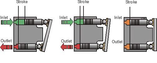
Figure 5. Swash plate angle dictates fluid volume displacement.
Some axial variable volume piston pump swash plates are designed to change the angle positively and negatively from perpendicular effectively reversing the inlet and outlet ports of the pump. Simplistically speaking the hydraulic drive system of a skid steer, or zero-turn mower, has one of these axial variable volume pumps on each side of the machine with the swash plate of each pump controlled by a lever. The fluid output of each pump goes to an actuator motor connected to the drive wheel(s) on the respective side of the machine. Push both levers fully forward and it is full speed ahead. Keep one lever forward and pull the other fully back and suddenly you are spinning around. Move both levers to their center positions and the machine stops. Without changing the pump or engine rpms, the skid steer can go from stopped to full speed ahead, full speed in reverse or, if you want to joy ride a little, you could spin clockwise or counterclockwise. Spinning at high speed or for too long may lead to operator dizziness and is not recommended.
Variable volume pumps may be designed with pressure, or load, sensing capabilities to limit pressure build up in the system and, thus, protect it similarly to, and possibly in replacement of, the pressure relief valve mentioned previously. System pressure will push the variable volume pump to a neutral, or near neutral, position as the system approaches the set maximum pressure. All systems have some internal leakage and, thus, to maintain the system pressure, the pump still needs to supply the pressurized system with some oil flow to maintain the pressure. The advantage of this mechanism for pressure control is that it doesn’t create the additional heat created by a relief valve dumping the full volume of pressurized fluid flow back to the reservoir. The pressure sensing controlled pump generates a minimal fluid flow to only replace internally leaked fluid.
Axial piston pumps also have non-variable volume variations. They are in-line pistons with a fixed swashed plate or a bent-axis type pump. The cylinder block housing of the bent-axis pump is at a fixed angle relative to the axis of the input shaft, thus creating the piston stroke. Fixed displacement pumps produce flow proportional to the piston size, number of pistons and rpms.
Piston pumps not only are preferred for variable volume applications but also offer much higher system pressures, some as high as 10,000 psi, compared to vane and gear pumps that may go as high as 4,000 psi. Additionally, piston pumps are more efficient and can generate maximum torque at low speeds, which is key for vehicle drive applications. Gear and vane pumps have more internal leakage between the sealed chambers of the pump and, thus, do not generate as much torque at low speeds. Piston pumps are more expensive than vane and gear pumps making them not practical for lower pressure systems where they are not needed.
Next month, we’ll talk about some of the other hydraulic system components. At first glance, the system pump may appear to be the most critical component, but it cannot work or survive without proper design, arrangement and maintenance of other components. The reservoir, for example, must do a lot more than simply store the hydraulic fluid.
Dan Holdmeyer is retired from Chevron Lubricants and is based in Washington, Mo. You can reach him at dan.holdmeyer@gmail.com.