Meet the Presenter
This article is based on a Webinar presented by STLE Education on Nov. 9, 2022. Understanding and Controlling Water Dilutable Metal Removal Fluid Failure is available at www.stle.org: $39 to STLE members, $59 for all others.
John Burke recently retired from Quaker Houghton. He received his engineering degree from the University of Dayton in 1971. He has more than 50 years of experience in the metalworking industry. He has 11 U.S. patents and many international patents. He is the author of two chapters in the book “Metalworking Fluids, Third Edition.” Burke has been an instructor for the STLE metalworking fluids education course for the past 26 years. He is an STLE Certified Metalworking Fluids Specialist™ (CMFS). Burke also is an associate editor for the STLE-affilicated journal Tribology Transactions. He received the STLE P.M. Ku Award in 2006 and has been an STLE Fellow since 2011. In 2015 he received the John A. Bellanti Award for dedicated service from ILMA. Burke received Governors Awards in Ohio and Tennessee for waste minimization projects. He received an award from U.S. President George Bush at the White House in 1991 for advances in waste minimization.
You can reach Burke at john.burke@quakerhoughton.com.

KEY CONCEPTS
•
Metalworking fluid (MWF) failure happens; however, there are effective ways to control it.
•
Selection of a robust MWF technology is critical for a machining site.
•
Basic understanding of an MWF technology will significantly benefit end-users.
All figures and tables courtesy of Quaker Houghton.
In machining of high precision parts, the dimensional variation of the cutting process is very critical. The demand for high quality and fully automated production places a lot of emphasis on the cutting process, which has a major contribution to part quality. Metalworking fluid (MWF) has been a key factor to machining performance and a key contributor to increase the effectiveness of machining systems. In this way, MWFs (i.e., metal-removal fluids) play an important role in minimizing production time, cost and energy in different machining operations. Maintaining and operating MWFs is a huge cost driver for the user.
1 Understanding and controlling MWF failures can greatly reduce the volume of the MWF used and, thus, the overall machining cost of the site.
This article is based on an STLE Webinar presented by STLE Fellow John Burke, CMFS, consultant to Quaker Houghton. See Meet the Presenter for more information.
This article gives an overview of the five basic failure mechanisms of an MWF, steps on how to control these mechanisms and then a brief summary. It will cover water dilutable fluids.
What causes an MWF to fail?
As shown in Figure 1, MWF changes over time, which is caused by a number of reasons. There are five primary failure mechanisms that cause fluids to fail. They can act independently or in combination with each other:
1.
Attack by positively charged contaminants
2.
Effects of negatively charged contaminants
3.
Effects of extraneous oils (tramp oils)
4.
Loss of pH
5.
Effects from microorganisms (bacteria and fungus).
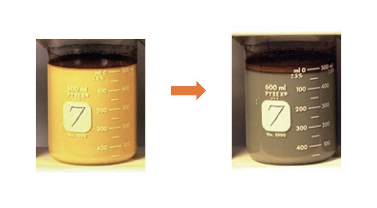 Figure 1. MWF changes over time.
There also are less common failure mechanisms that can be equally damaging to the fluid. When performing MWF troubleshooting, some additional failure mechanisms should be considered:
•
High shear forces—cavitation
•
High temperatures: +180 F
•
Oxidative reactions
•
Galvanic reactions
•
Evaporation of alkaline components— amine loss
•
Evaporation of light oil fractions
•
Leaching of zinc, lead and copper
•
Hydrolytic stability of biobased esters
•
Selective additive stripping— defoamers, oil-like components
•
Poor cold-water mixing
•
Freeze/thaw stability
•
Poor initial mixing
•
Poor grounding/stray direct currents/storage tank.
However, if an MWF is well-managed, there are many benefits to a site, which vary on site conditions:
•
Cleaner and safer working environment
•
Less waste to dispose
•
Extend the life of the MWF
•
Improve tool life and the consistency of metal-removal processes
•
Reduce overall operating cost.
MWF (coolant) makeup cycles
The MWF is a key variable. If an MWF is required to make a part, then as that MWF changes in quality or quantity, it also has an effect on final part quality.
Figure 2 shows a fluid that was filtered to 30 microns; additionally the following items were used:
•
Basic emulsified oil
•
Cast iron grinding
•
Water hardness = 120 mg/L.
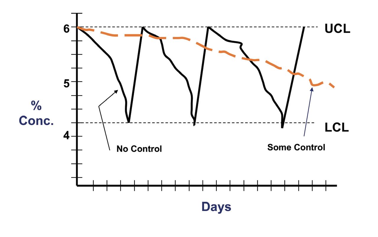 Figure 2. Coolant makeup cycles (UCL = upper control limit, LCL = lower control limit).
Cast iron fines were removed from the system within minutes of chip formation. The fluid lasted beyond 18 days.
There are multiple variables in the metal-cutting process
(see Figure 3). Any one of these variables can affect finished part quality; however the condition of an MWF is a key variable. If an MWF is needed to make a part, then as that MWF changes in quality or quantity, it will have an effect on final part quality as well.
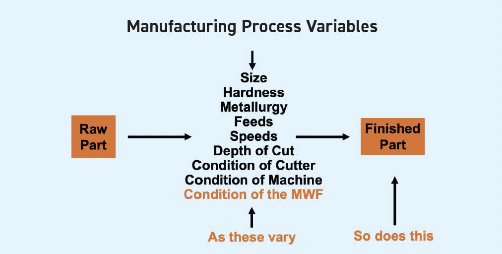 Figure 3. Manufacturing process variables.
Can failure rates be modified?
An experimental trial was conducted on 15 machines. All machines were doing the same job, including cutting the same type of metal, making the same parts. The first week of the trial, samples were taken from the sumps of the 15 machines. Sample #1 and Sample #15 were left as is, filled with control fluids, while all the other samples were adjusted with better water, filtration, biocides and combinations thereof. Figure 4 shows that some of the fluids look better, then others after one, five and 15 weeks of operations. All fluids were still making parts, albeit not very well in the case of #1 and #15. The test ended at the 15-week period, mostly due to the fact that production suffered, and workers complained of odors. Samples #9, #10 and #14 were still making good parts.
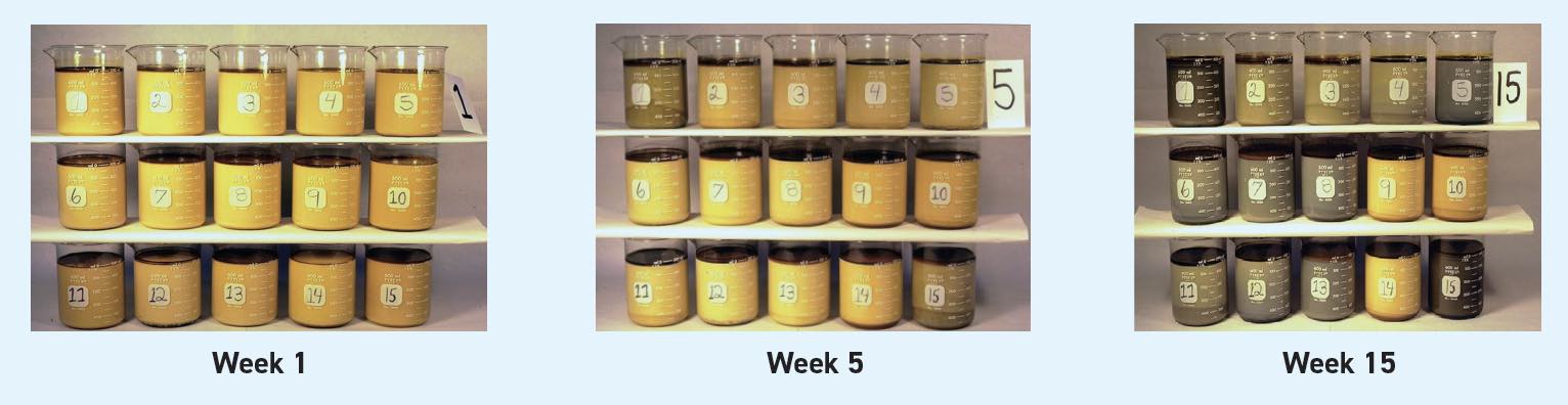 Figure 4. MWFs experiment: Visual results after 1 week, 5 weeks and 15 weeks.
At the end of this experiment, certain samples looked better than others; Sample #10 had some control with biocide and filter, and Sample #9 showed the best results
(see Figure 5). Sample #9 used purified “low hardness” water, was filtered to 30 microns, then pH was adjusted upward to 9.0, water was used prior purified by reverse osmosis (RO) and a triazine biocide was added in small doses throughout the trial. Note, the tramp oil was not removed during any part of this testing. Clearly, or at least visually, the failure rates can be modified.
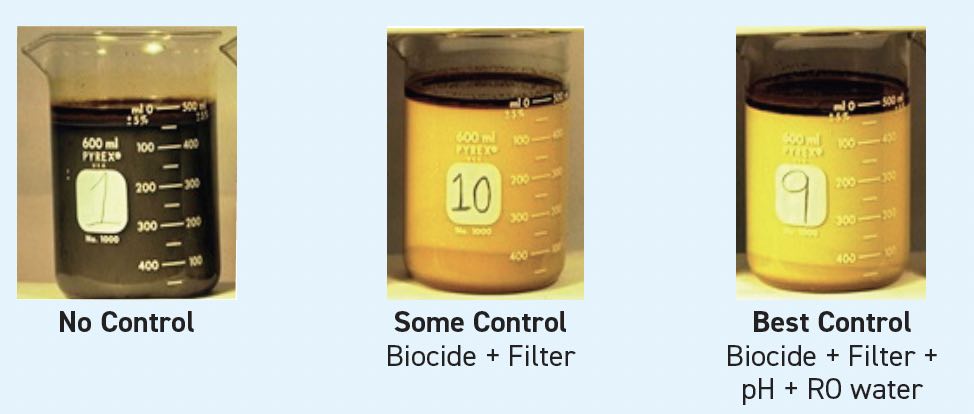 Figure 5. MWFs experiment: A closer look at the visual results after 15 weeks.
Although Sample #9
(see Figure 6) looked good, there was still a significant amount of tramp oil in the fluid, and the fluid was starting to phase separate. It was clearly not as good as observed in the first week of the trial. The questions to be answered:
•
This fluid “looks good,” but can it machine at optimum feed and speeds with it?
•
Is it still safe to the worker?
•
Should this fluid be discarded?
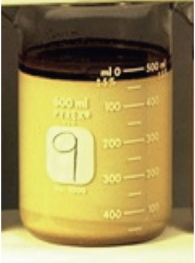 Figure 6. Sample #9.
Tool life versus time
Figure 7 shows another experiment. The process was a turning of SAE 8620 steel (gear steel), and coated carbide inserts were used. It started with the plant water, which was rather hard, and at a later time water hardness was lowered to 205 mg/L. The machining performance of the fluid was increased from 12 weeks to 16 weeks, a 30% improvement. However, tool life continued to decline since only one failure mechanism was addressed. Pushing the fluid past 16 weeks continues to show a decline in tool life. In other words, there can be a point of diminishing returns; while fluid life can be extended, the tool life (productivity) will decline.
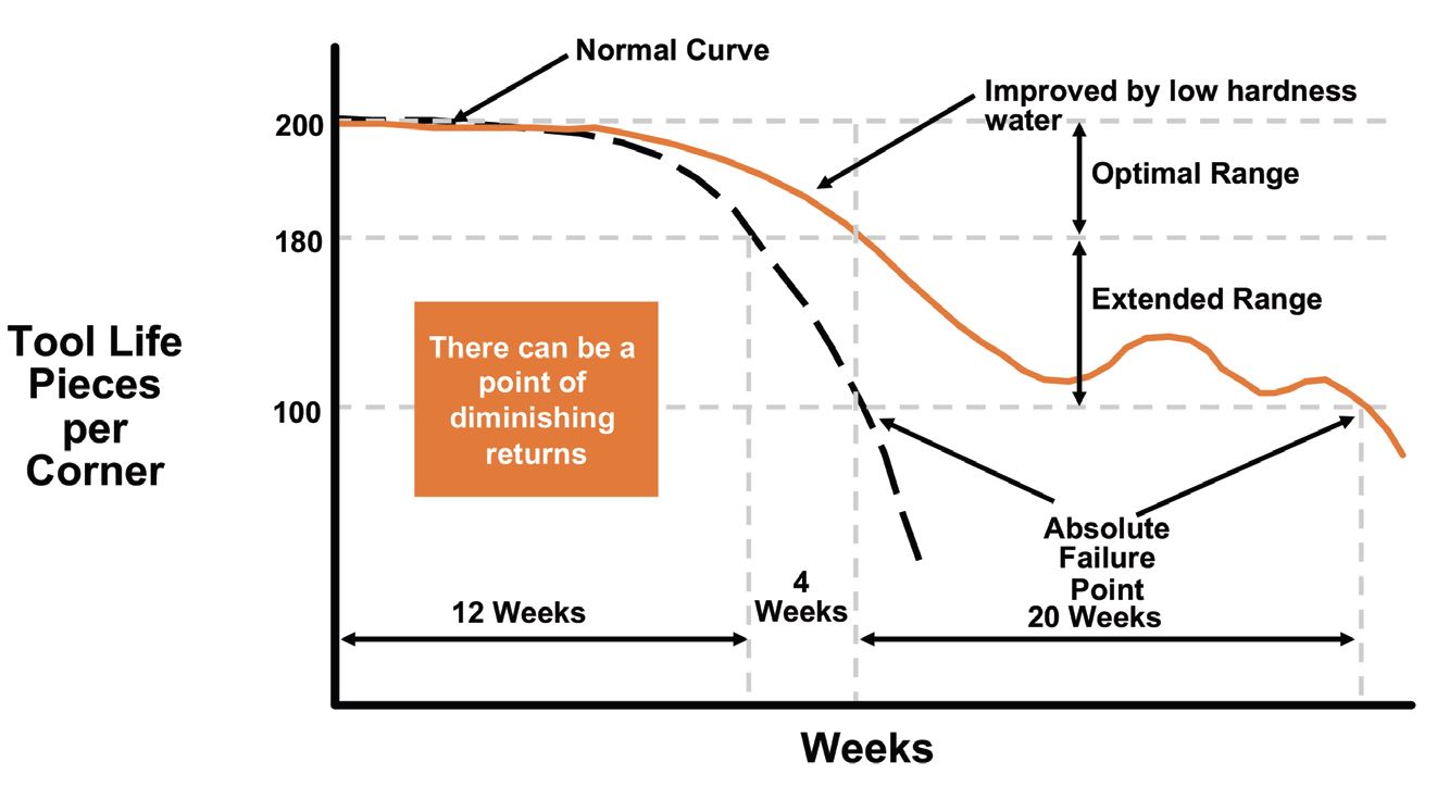 Figure 7. Tool life versus time experiment.
Failure mechanism #1: Cation attack
Most fluids today can be categorized into three basic formulations. The fluid components that are bolded
(see Table 1) are negatively charged, which means that the machining process is occurring with the metal that generates positive charges.
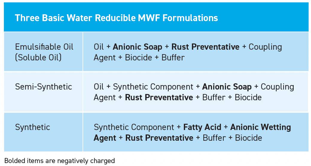 Table 1. Three basic water reducible MWF formulations.
Table 2 shows different metal categories used during a machining process. Metalworking machining exposes very reactive metal surfaces. Some metals are more reactive than others. Iron and aluminum can expose three positive charges. Magnesium can have two positive charges. Stainless (nickel) alloys are generally not reactive metals.
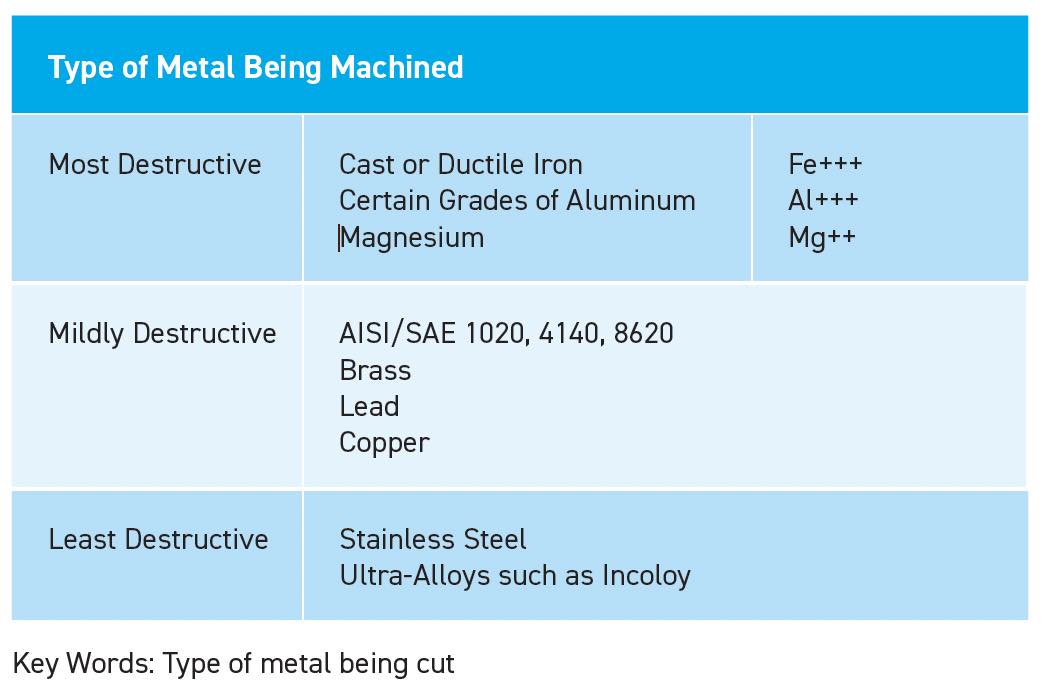 Table 2. Different metal categories used during machining process.
Basic emulsified oil is dispersed in a fluid because the oil droplets have induced negative charges from the emulsifying chemistries. If these fluids are not exposed to a metalworking operation, or any other failure mechanism, they can remain stable emulsions for years
(see Figure 8).
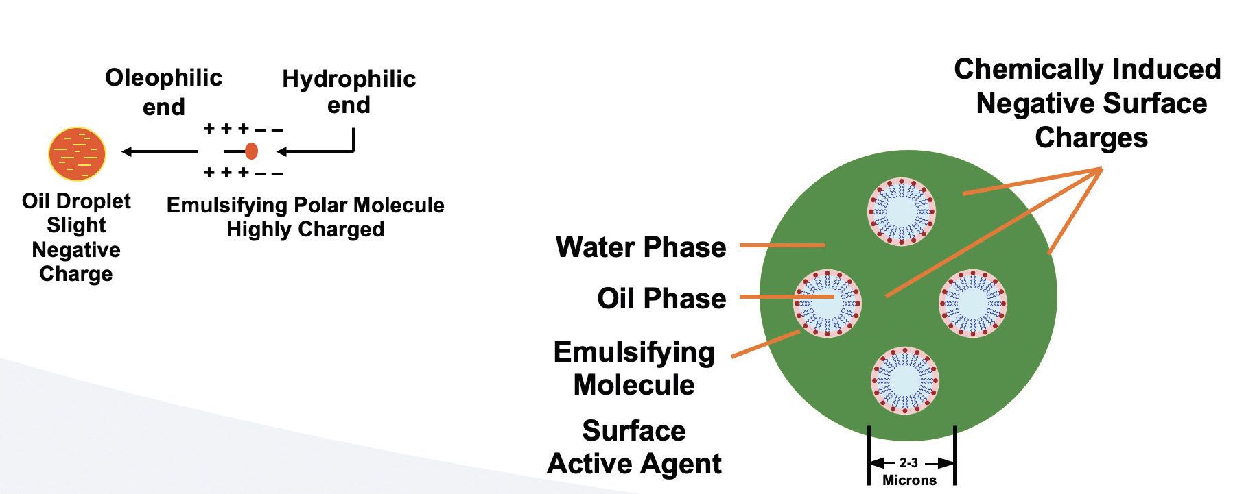
Figure 8. Typical emulsified oil MWF schematic.
When freshly machined metal is exposed to dispersed oil droplets, the oil begins to agglomerate around the oil droplets
(see Figure 9).

Figure 9. Typical emulsified oil MWF schematic on the road to failure.
The surface charges of the oil droplets are not neutralized, but they are electrochemically bound to the charged metal particle. The oil droplet and metal particles become larger (now 10 microns or larger versus initial 2-3 microns), and they begin to float, resembling tramp oil
(see Figure 10).
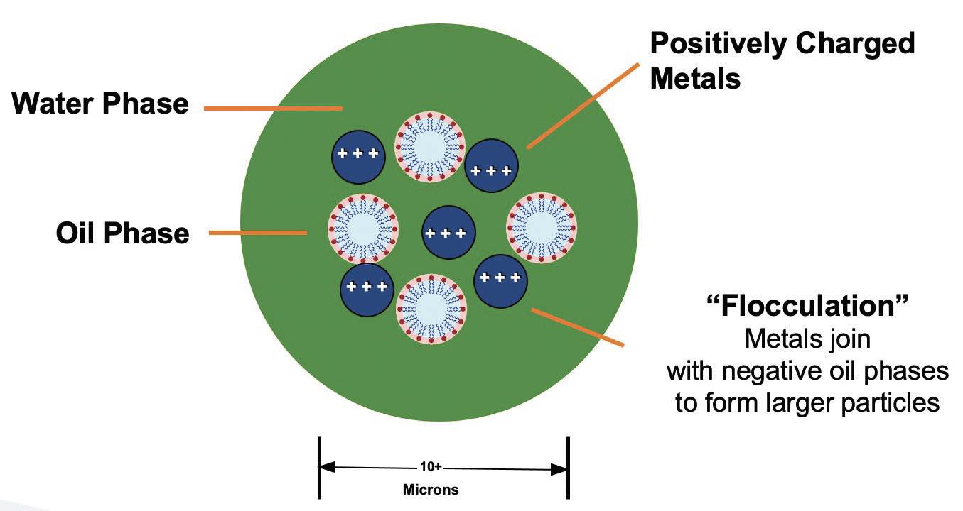
Figure 10. Typical emulsified oil MWF schematic.
Figure 11 shows test rigs for a cast iron grinding experiment that was conducted, where a large amount of very small metal particles was emersed into a small amount of MWF. The experiment intended to isolate one reaction (charged metal particles) and eliminate tramp oil, hard water effects, heat and biological effects. Three cast iron slugs were ground on 400 grit media.
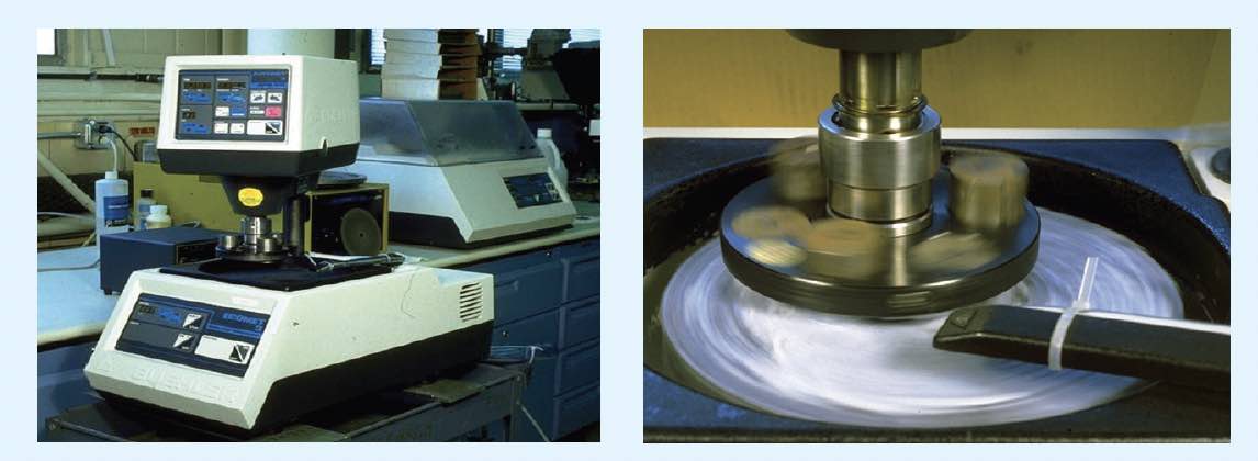 Figure 11. Cast iron grinding experiment: test rigs.
The starting concentration of MWF was 20% oil, and as Figure 12 shows, it has split out in just 15 minutes to about 10%. This simple test supports the theory that reactive iron fines can destabilize an MWF. Also note that the floating material on top of the MWF is not a tramp oil, but more likely iron soaps (for this fluid type). Note only metal reaction was isolated in the experiment—there were no other reactions.
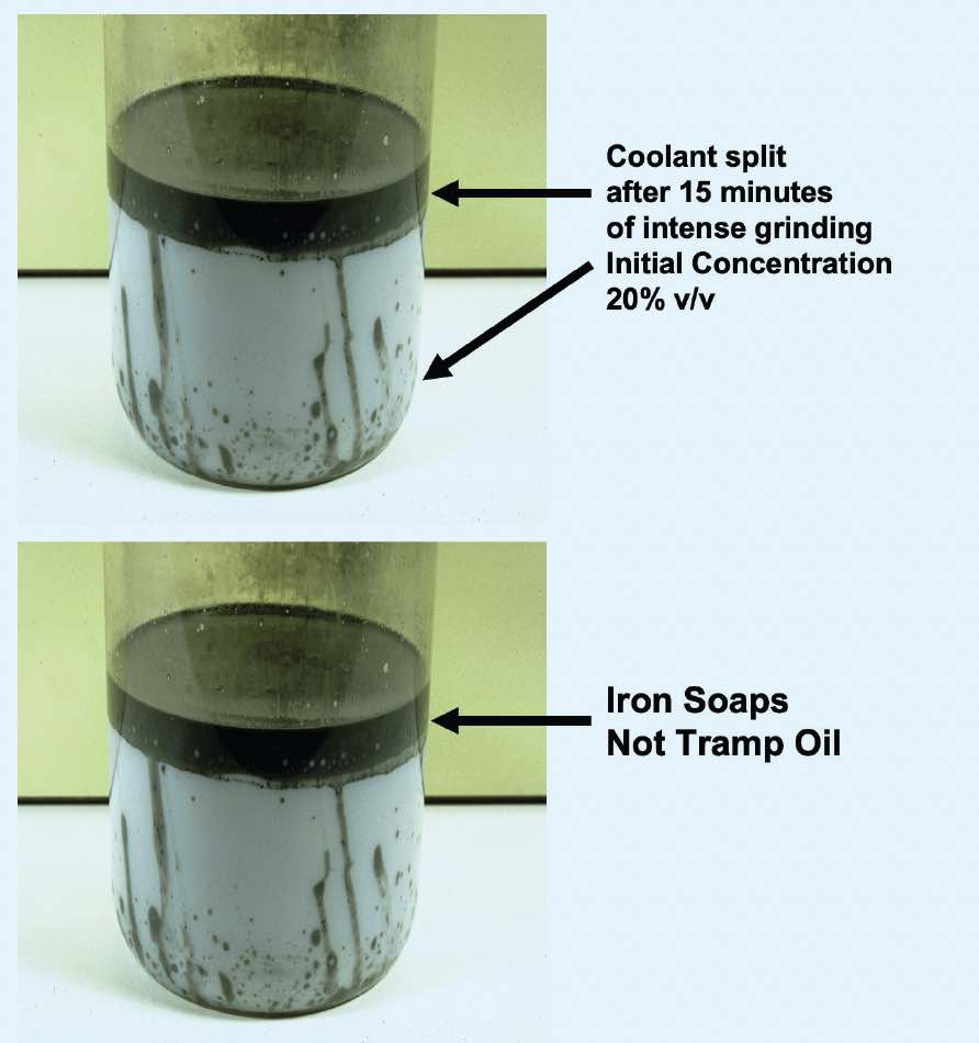 Figure 12. Cast iron grinding experiment: fluid separation.
Since metal fines are reactive, it is because of the positive charges on the surface and not the total weight of the metal machined. Therefore, small metal particles, such as the result of grinding, generate more surface area per pound of metal machined
(see Table 3).
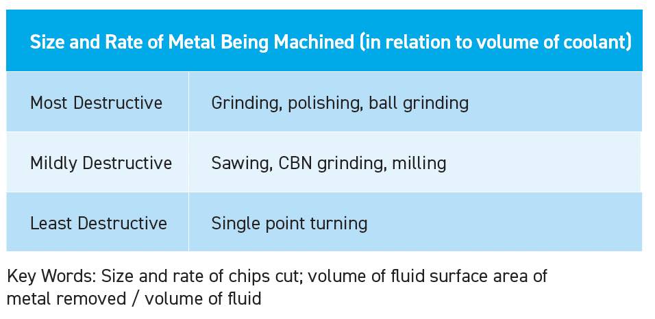
Table 3. Size and rate of metal being machined (in relation to volume of coolant).
To add to the above statement, it is well known that machining generates a lot of surface area
(see Figure 13).
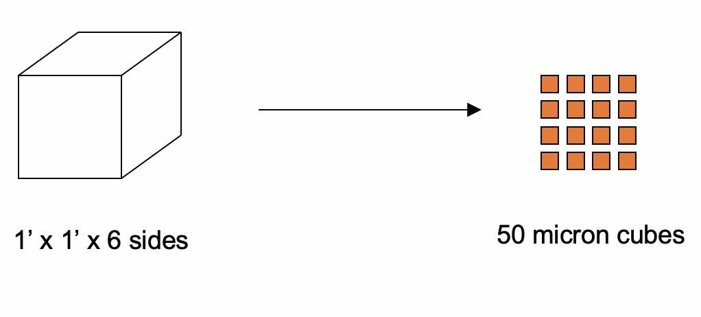
Figure 13. Surface area generated by machining—6 square feet become 35,720 square feet.
An example is a simple calculation of taking one square foot of steel and grinding it into 50-micron cubes: starting with 6 square feet of surface area and moving to 35,720 square feet of surface area represents 6,000 times increase in surface area. For reference, that is more than half the area of an American football field.
Filtration example: Cation attack
In a real-world example, with even smaller particles, the same metal fine “cation reaction” occurred in a five-day period. A better filter for the system may have helped. Also, copper “soaps” formed making finer levels of filtration more difficult:
•
15,000 gallon system
•
Copper alloy
•
Wire drawing–copper:
°
1,000 total suspended solids
°
210 mg/L <8 micron
°
168 mg/L <0.45 micron
°
120 mg/L <0.2 micron
•
Over time, metal particles built up linearly while surface area of dirt built up exponentially.
•
Once coolant hit these dirt levels, failure occurred in five days
Water is the next area of cation attack. Water used in the machining industry generally includes a salt such as calcium carbonate
(see Table 4). Water can be purified by various means.
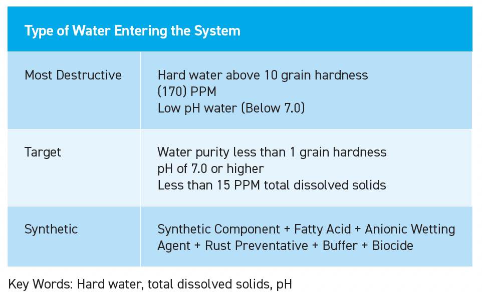 Table 4. Type of water entering the system.
There are several areas of concern when using a municipal water as is. Table 5 shows the water analysis, which a fluid manager was asked to review for a “staining” problem at a manufacturing plant in Canton, Ohio. Note, it is not common to have such an extensive water analysis available from a municipality or water district.
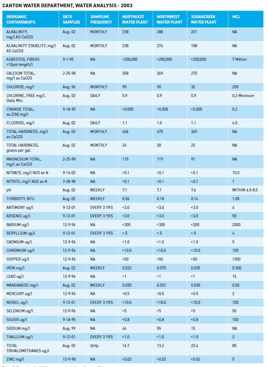 Table 5. Example of a 2003 water analysis from Canton, Ohio.
Table 6 shows the same water analysis from Ohio with some of the key components of the water separated out. Three water sources are from wells and not surface waters. Each well varies significantly from each other. This can explain why the problems at this manufacturing plant were sporadic. One well has a water hardness of 475 mg/L. This is very hard water and not generally suitable for MWFs. High chlorides can lead to rust. The staining issue at this plant was wrongly identified, but it was actually the rust. In a later analysis, the recirculated water had a chloride level of 285 mg/L. At this level of chloride, rust is expected on fresh cut iron alloy metal surfaces.
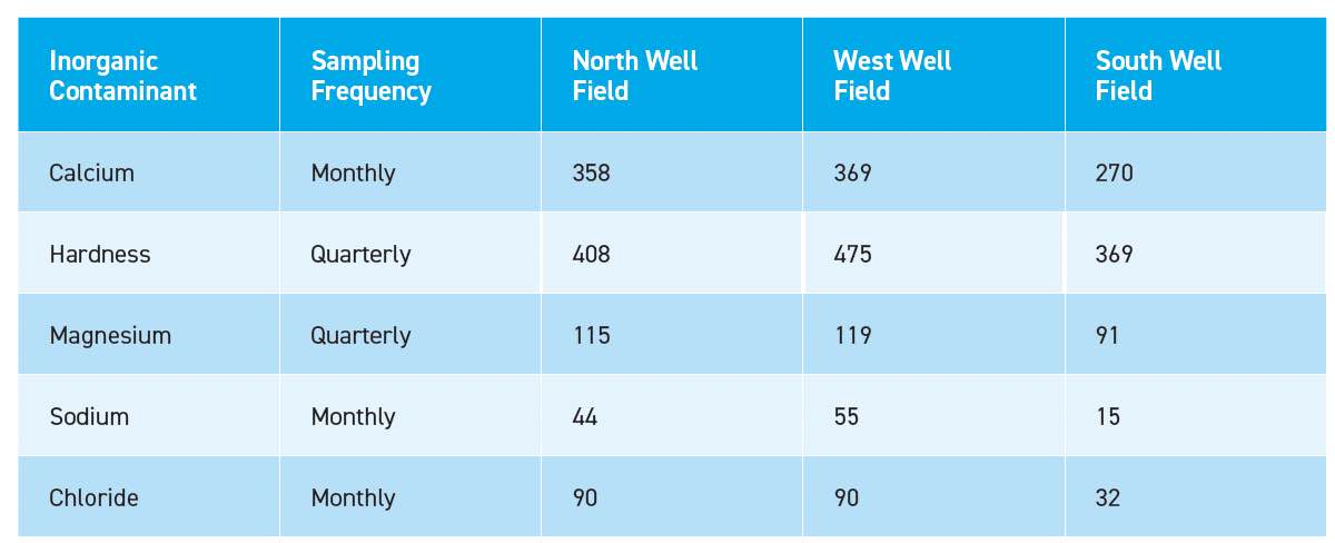 Table 6. Example of a 2003 water analysis from Canton, Ohio, sources (wells) are separated.
The water amount that enters the system, depending on the volume, can be very destructive
(see Table 7). In the metal-cutting process, the water phase of the MWF generally evaporates faster than the oil or synthetic phase. The salts in the water stay behind. As the salts from the incoming water enter into the fluid, they “cycle up” and become more concentrated due to evaporation. The destructive effects increase because the concentration of the contaminants (salts) in the water increases.
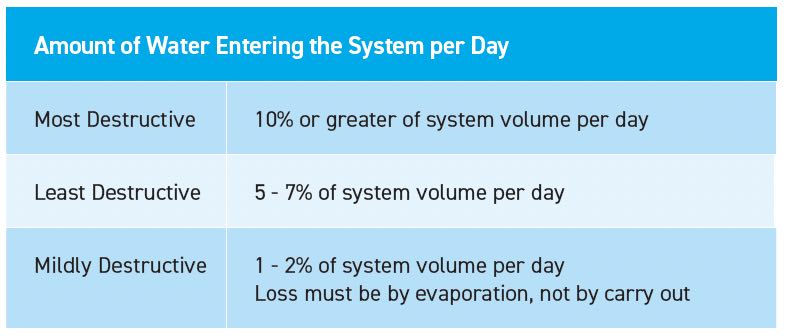 Table 7. Amount of water entering the system per day.
Figure 14 shows a premium emulsified oil: a side-by-side comparison of the three cycles of concentration. Note that only water was added as the water phase evaporated. Salts stayed behind and split the MWF.
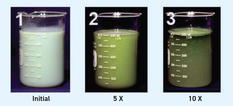 Figure 14. Premium emulsified oil—effects of evaporation and water at 120 ppm hardness.
Sample 1
(see Figure 14) shows an MWF that is stable in 600 ppm hardness water. The water phase was evaporated very slowly over the course of days to build up salts in the water. The starting hardness is 120 ppm (120 mg/L).
•
Premium emulsified oil
•
5% by volume
•
Water 120 ppm
•
Initial concentration.
Sample 2
(see Figure 14) shows five cycles of concentration; this MWF is barely holding together. Note the “cream” layer residue at the top of the beaker.
•
Premium emulsified oil
•
5% by volume
•
Water 600 ppm
•
After five concentration cycles.
Sample 3
(see Figure 14) shows fluid after 10 cycles of concentration; the fluid has completely separated. This represents the isolation of one reaction. No metal fines were present, no tramp oil and no bacteria, but the MWF still split. This is another form of cation attack on an MWF.
•
Premium emulsified oil
•
5% by volume
•
Water 1,200 ppm
•
10 concentration cycles.
To summarize, there is one group of failure mechanisms that are positively charged cations and another group with key components that are negatively charged. For cation attack, both reactive metal fines and hard water salts can cause an MWF to fail. Reactive metal fines and hard water salts can both be present in the manufacturing environment
(see Figure 15). It is like links of a chain: if the chemical links in an MWF formula are destabilized, then the MWF also is destabilized and can cream out and ultimately phase separate.
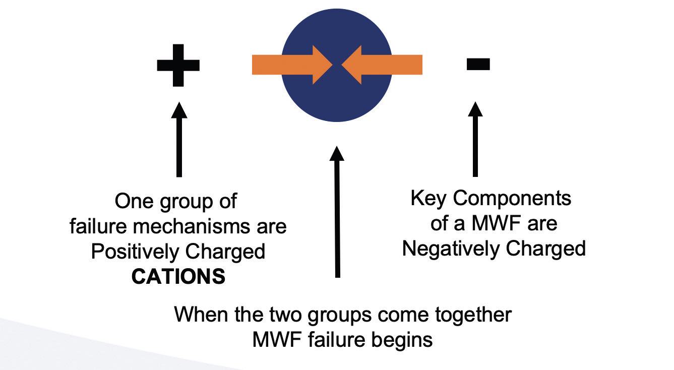 Figure 15. MWF failure schematic.
Pure water usage in machining operations
Although there are many advantages of using low hardness and low anion water for MWFs, there are two potential disadvantages. Hard water soaps have some level of lubricity. Using pure water without hardness will not create soaps, and tool life can diminish in some operations like tapping and reaming
(see Pure Water Myths: True or False). Also, hard water soaps can weaken the emulsion, but that also will lessen foam generation. Without these hard water soaps, foam is a possible outcome and is a potential reduction in tool life.
 Pure water myths: True or false
Statements
1.
Softened water is OK for use in coolants.
2.
Rainwater or air conditioning condensate is OK for coolants.
3.
Pure water has a pH of 7.0.
4.
One water analysis is all I need to make further decisions about my water concerns.
Answers
1.
False. Water purified by a sodium chloride regenerated softener will leave white deposits and increases the risk of chloride corrosion.
2.
False. While the rainwater may be soft, when it hits the roof, it is full of dirt and bacteria, fungus and algae—the same for air conditioning coils.
3.
True but only for a while. It absorbs carbon dioxide from the air and turns acid, as low as 5.5 pH. Even though the water can be as low as 5.5 pH, it is weakly buffered and generally will not affect the final diluted pH of an MWF that is highly buffered at pH 9.0 or above.
4.
False. Most water sources wary considerably: seasonally and sometimes even hourly.
Advantages of using pure water:
•
Easier mixing
•
Smaller particle size
•
Improved wetting and penetration
•
Minimizes gummy residues
•
Improved filtration
•
Less carry-off
•
Greater bacterial resistance
•
Greater fungus resistance
•
Reduced corrosion
•
Less concentrate use
•
Less mist
•
Better overall stability.
Disadvantages of using pure water:
•
May lessen tool life in some operations
•
Increases risk of generating foam.
Failure mechanism #2: Anions
Not only the cations, but the anions require attention, too
(see Table 8). The most devastating of all the anions found in a wastewater treatment are chlorides. Chloride levels as low as 120 ppm can cause rust on iron alloy surfaces. There is no practical treatment to stop chloride corrosion once the corrosion starts. High levels of sulfates and phosphates are nutrients for microorganisms, therefore supporting microbial growth issues that may require further treatment.
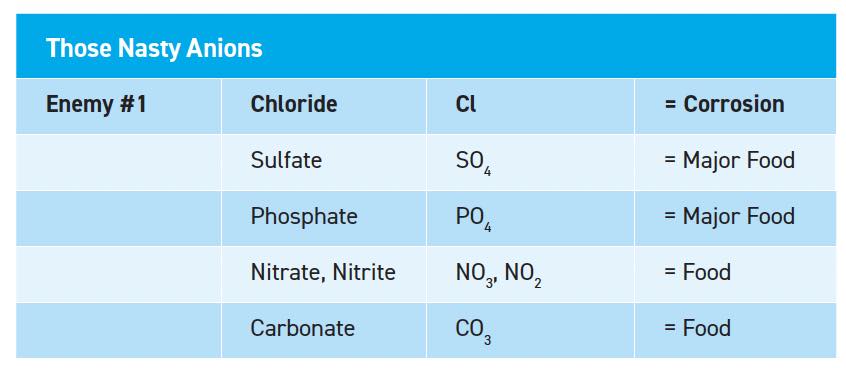 Table 8. Negative effect of anions on MWF, being “food” sources for bacteria.
Figure 16 shows a traditional dual bed deionizer system, which is one method to remove cations and anions from incoming water used to dilute MWFs. These systems can be referred to as deionization or demineralization processes. These typically use hydrochloric acid and sodium hydroxide for regeneration. If the system fails, then hydrochloric acid or sodium hydroxide can enter the MWF. Operating caution and periodic maintenance are recommended. Extremely pure water can be obtained by this method, with conductivity less than 1.0 microsiemens/meter (μS/M).
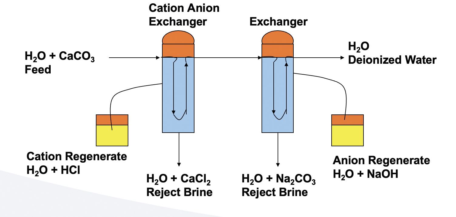 Figure 16. Traditional dual bed deionizer system.
RO is a more popular and simpler process when water is abundant
(see Figure 17). The final water conductivity can be as low as 5.0 microsiemens/meter. Typically, the membranes can reject up to 99.7% sodium chloride (NaCl) and other contaminates. Pretreatment can be by a traditional sodium chloride water softener or by the use of anti-scalants. Membranes, with proper care and pretreatment, can last upward of three years. Cold water flows more slowly through RO membranes versus warm water. Water temperature variations need to be considered when sizing RO systems. For every 100 gallons of water starting, only 70 gallons can be recovered as treated water, and the remaining water (30 gallons) is rejected. Therefore, RO systems may not be suitable for use in arid areas or where water is scarce.
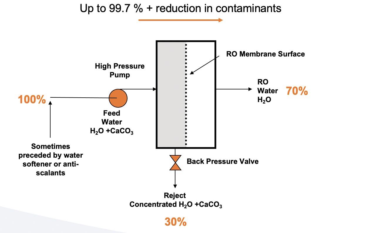 Figure 17. RO water system.
However, all water conditioning systems (water purification systems) can fail or be bypassed. In addition:
•
They can actually produce worse water than the water it was started with.
•
They can confuse users into thinking that the water is treated when it is not.
•
They can fail intermittently, and/or without warning.
A word to the wise:
•
Never totally trust a water purification system.
•
Always check.
Failure mechanism #3: Tramp oil
Tramp oil is a term that describes any undesired oil (typically from leaks) in MWF. The additives in hydraulic oils, way oils, spindle oils and gearbox oils are just as problematic as the oil itself. The more fortified the oil for whatever its purpose, the more harm it can cause to the metalworking emulsion
(see Table 9).
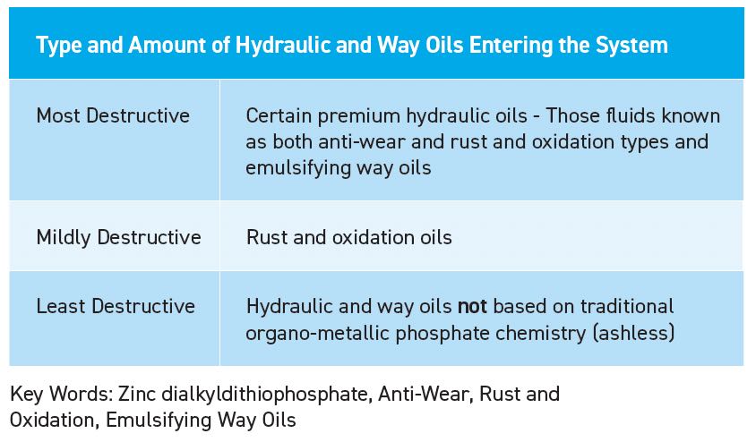
Table 9. Type and amount of hydraulic and way oils enter the system.
Tramp oil
(see Figure 18) is never just “petroleum oil.” It contains additives that can wreak havoc with most MWFs. The additive packages in tramp oil can transfer into the water phase or into the oil phase of an emulsion. The negative effects of tramp oil are not easily reversible
(see Tramp Oil Myths: True or False).
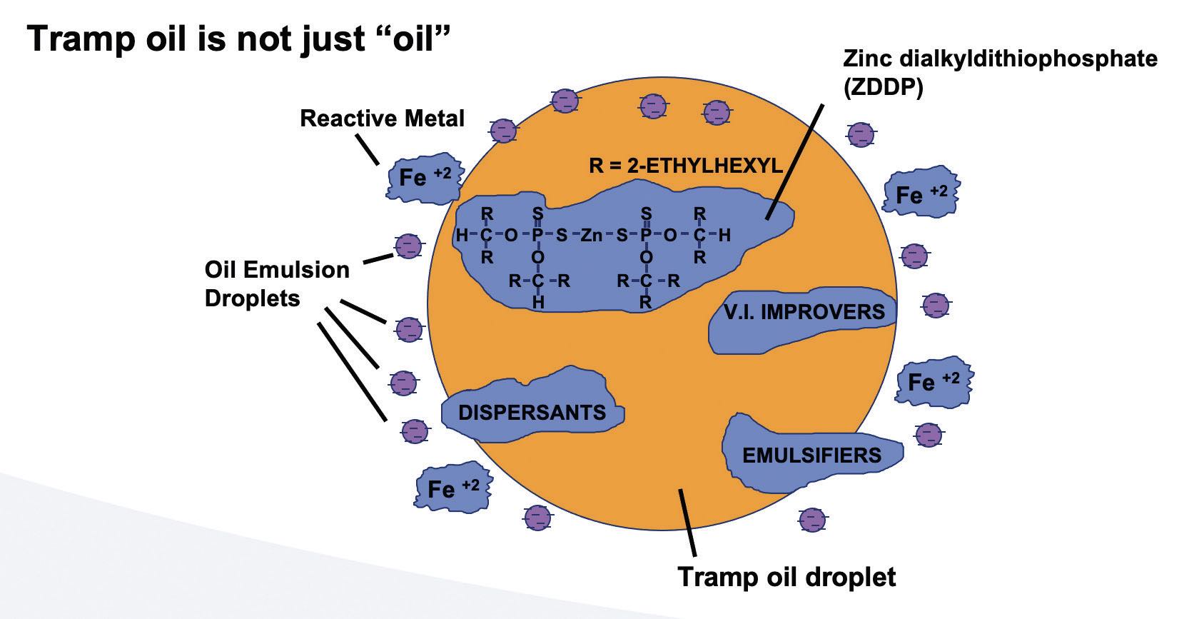
Figure 18. Tramp oil schematic.
 Tramp oil myths: True or false
Statements
1. If I add emulsifiers to the coolant mix, I will eliminate the effects of tramp oil contamination.
2. A centrifuge will solve my tramp oil problems and not remove the original emulsion product.
Answers
1. False. The current general practice in the industry is to remove tramp oils as soon as practical and not let them become part of the MWF.
2. False. The oil phase of “tramp oil” is soluble to other oil-like products in the original MWF and will be removed together.
Here are key tramp oil failure theories:
•
Sharing of the emulsifier— the hydrophilic-lipophilic balance (HLB) theory
°
Too much oil, not enough emulsifier, fluid starts splitting
•
Reactivity of the zinc dialkyldithiophosphate (ZDDP) molecule
°
Sulfur and phosphorus availability; food for bacteria (bacterial nutrients)
•
Dispersants and de-emulsifiers in hydraulic oil upset the HLB balance.
All three theories are valid. The HLB of a surfactant is a measure of the degree to which it is hydrophilic or lipophilic. Add too much tramp oil with a fixed amount of emulsifier and the emulsion starts to cream out. There are many scientific articles written about the HLB theory. Tramp oil is a term that describes any undesired oil (typically from leaks) in MWF.
Failure mechanism #4: Lack of pH control
Generally, the pH of an MWF will decline over time. It is a misconception that maintaining a high pH will eliminate issues with microorganisms. The surfactants and emulsifiers used in MWFs are designed to perform best in the range of 9.0 or above. Too high a pH can result in dermatitis and eye, nose and throat irritation.
Failure to control pH can result from several different causes:
•
Amines can evaporate and pH will drop.
°
This can happen more in winter (low humidity) than summer months.
•
Certain microorganisms as they proliferate will release acids and thus lower pH.
•
There are acceptable operational ranges for traditional MWFs.
The correct range for pH is between 9.0 and 9.3
(see Figure 19). Many premium fluids have sufficient alkalinity reserve to maintain pH within this range for extended periods. Seasonal variations (such as low humidity) and/or operating at temperatures above 120 F can result in loss of amines and subsequent decline in pH.
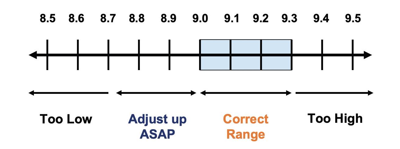 Figure 19. pH ranges for MWF management.
Failure mechanism #5: Lack of control of microorganisms
Control of microorganisms in MWF is a complex subject. In recent surveys of machine shops, odors attributable to bacteria and/or fungus were the No. 1 complaint or concern.
Maintenance of an effective biological control program is critical as:
•
Antimicrobial pesticides (i.e., biocides) are regulated by EPA.
•
Too little may be worse than none at all; resistant strains can grow in the fluid.
•
If some is good, more is not better; this will result in a worker irritation.
Unfortunately, part of the problem is that microorganisms can grow in a certain part of a machinery, which are called “dead spots.” In other words, dead spots are any area of a machine fluid system that does not have continual flow of the MWF
(see Figure 20). These dead spots can be piles of wet chips, blocked chip troughs or partially blocked piping or piping with dead or unused sections. These areas are significant contributors for adding to the microbial population of the metalwork ing system.
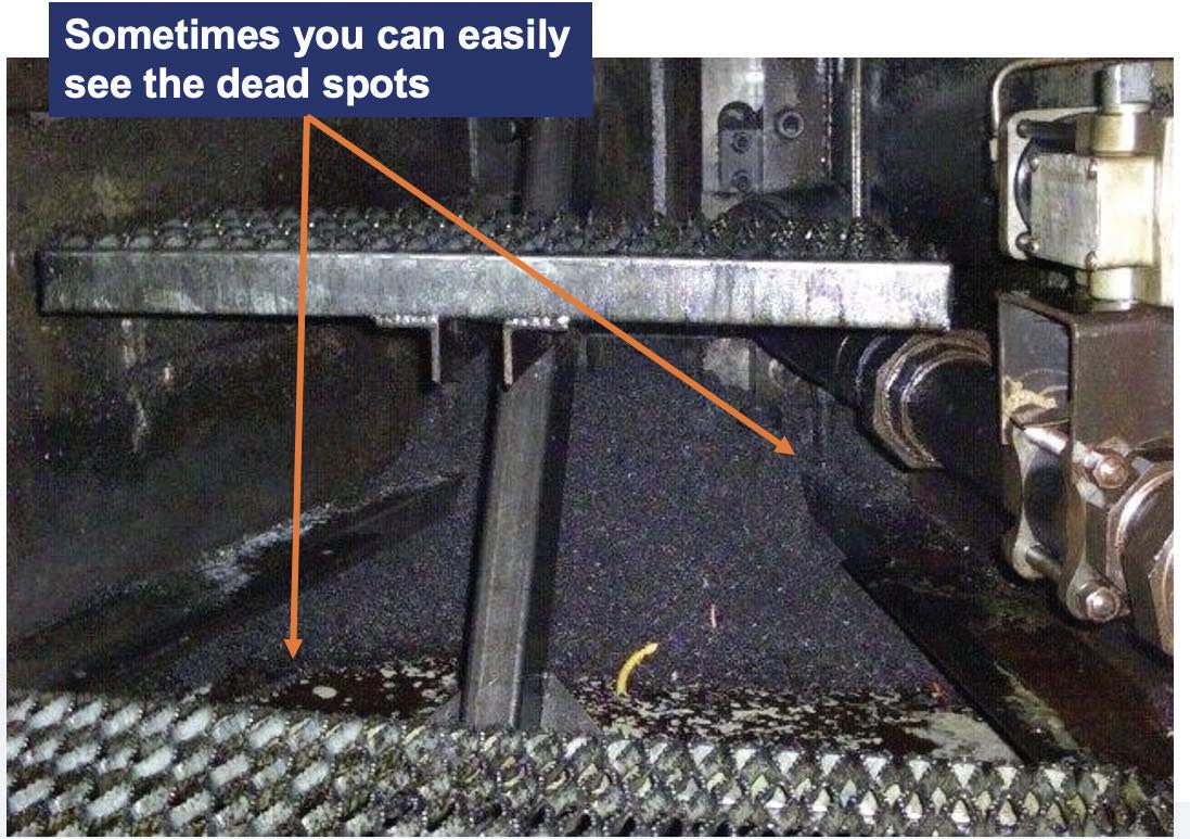 Figure 20. Example of a dead spot in a machining area.
Figure 21 shows a chip flume that was almost completely blocked. This plant had severe biological issues.
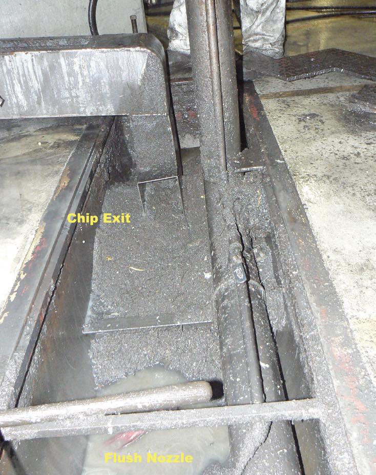 Figure 21. Example of a dead spot in a machining area.
Figure 22 shows a case where tramp oil and chips are accumulating in a corner of a machine tool sump with a minimal coolant circulation. All these dead spots examples cause havoc with any MWF.
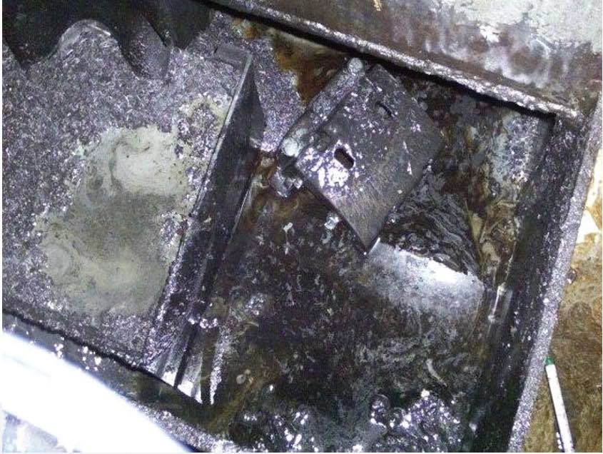 Figure 22. Example of a dead spot in a machining area.
Basic failure model: Water diluted fluids
It is rare that just one failure mechanism is causing an MWF failure. Typically, multiple failure mechanisms act in combination to render a fluid ineffective.
Figure 23 shows an excessive tramp oil that can be a food source for bacteria. Both the tramp oil and the bacteria levels need to be controlled and not just one or the other. It is for this reason as shown that all failure mechanisms need to be addressed and not just one for effective control of an MWF.
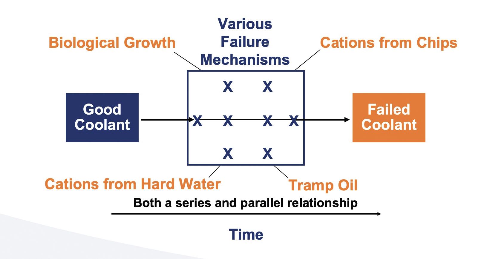 Figure 23. Basic failure model: water diluted fluids.
Waiting for a coolant to fail and then applying a corrective action will simply not work, i.e., if an MWF fluid is pushed to failure, it cannot be recovered into a like-new fluid
(see Figure 24).
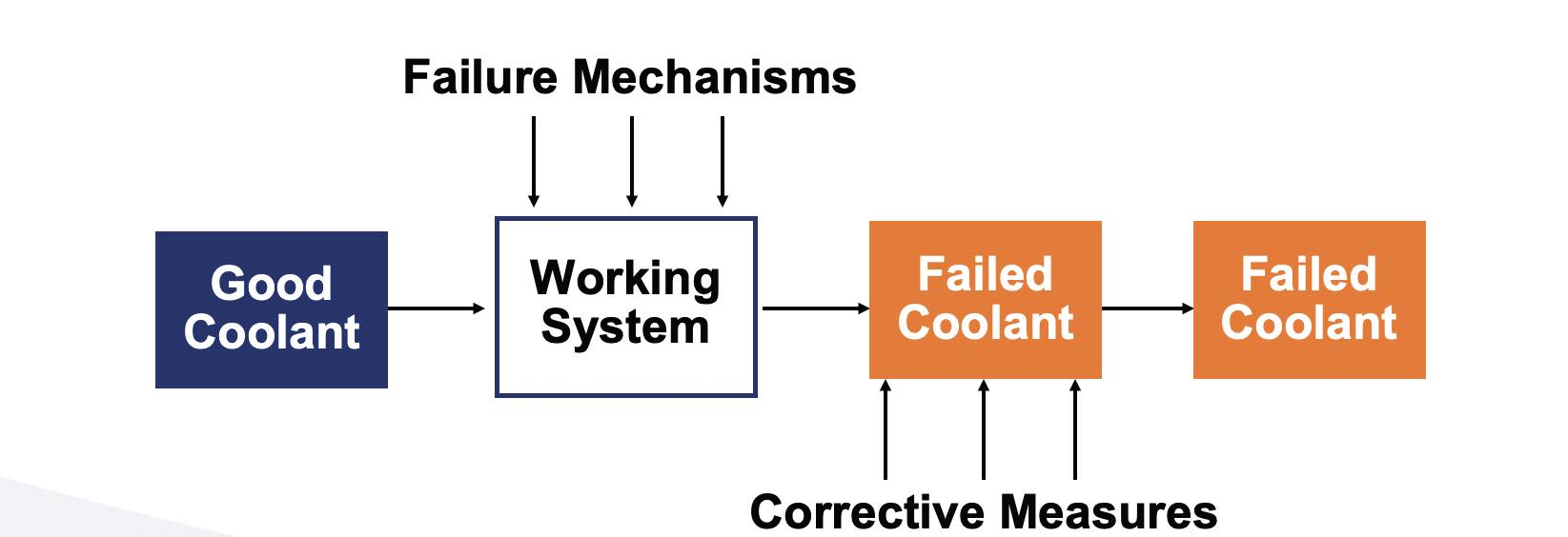
Figure 24. Ineffective approach to an MWF recovery.
Figure 25 shows that the proper way to control MWF failure is to address failure mechanisms as they occur, and not after the fact.
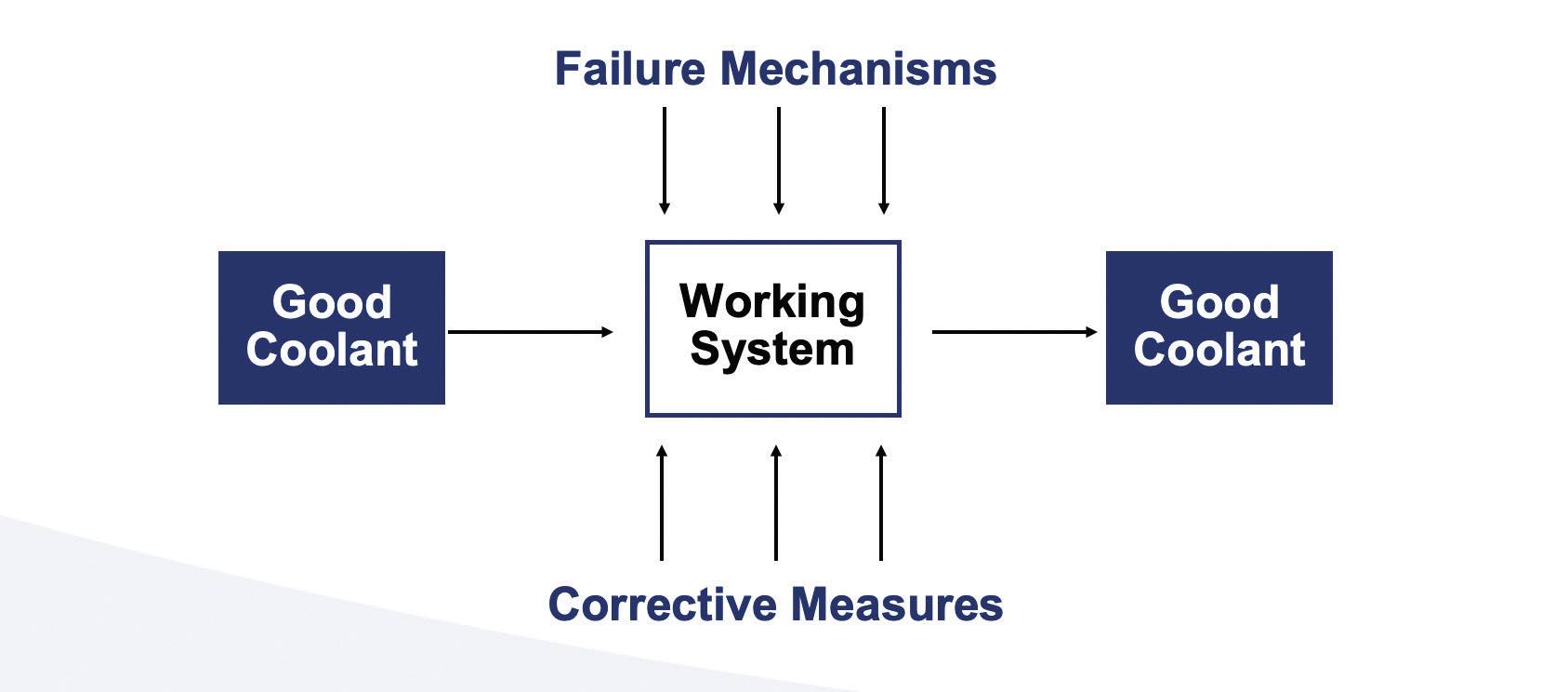 Figure 25. Effective approach to an MWF recovery.
Focus on failure mechanisms
Figure 26 shows MWF’s five failure mechanisms, but there also are less common failure mechanisms that can be of an issue.
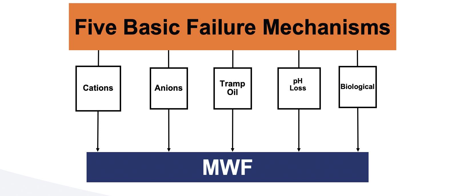 Figure 26. Five basic failure mechanisms.
Basic corrective actions are intended to be basic methods that an average manufacturing facility can follow. They are not intended to correct every problem that can occur.
Addressing all five basic mechanisms will likely result in success, but not in all cases. It may take a bit of study and investigation to determine if any of the additional failure mechanisms also are acting on the fluid causing failure.
Counteracting failure mechanism #1: Cation attack from metals
Effective filtration is a key. It is important to start at 30 microns with high loft filter media (typically with a weight of 2.5 ounces per square yard). After experimentation, the filter micron level can be lowered to 20 microns and then 10 microns. For emulsion type products, it is recommended not to use filter media below 10 microns. For true solution synthetic fluids, it is important to not go below 2 microns. Also, a good practice advised starts with a polyester media. Polypropylene media has an affinity for oil-like products such as petroleum oil and fatty acids. If there is a need to wick out a large release of tramp oil, then polypropylene media may be considered.
Counteracting failure mechanism #1: Cation attack from metals fix dead spots
Dead spots can contribute to a host of issues, mostly biological in nature. It may require a significant level of investigation to identify all the dead spots in a system.
Counteracting failure mechanisms #1 and 2: Cation and anion attack from water
RO should be the first choice for water purification. Small users of water can benefit from “service exchange” rental deionization tanks where the resins are regenerated off site. These services are available in most major cities.
Counteracting failure mechanism #3: Tramp oil
Although not always practical, fixing the tramp oil ingress is the best approach. Then, if the leaks cannot be fixed, installation of a continuous tramp oil removal system is required. Also, usage of a lower level of additives in the hydraulic oil system should be considered, but only if the hydraulic pressures are below 600 psig and hydraulic fluid temperatures are controlled below 160 F.
Note: Once the tramp oil is fully homogenized into the MWF (about two to three days), it will be nearly impossible to remove the tramp oil without removing the original MWF component(s). The metal being machined also contributes to the overall reaction as well as the particle size of the metal being machined.
Additionally, zinc is a highly regulated metal and can interact with amines in MWFs. Zinc is found in many areas in the manufacturing plant. When piping MWF for distribution in a manufacturing plant, it is recommended to use black steel pipes and not galvanized pipes or PVC pipes.
Counteracting failure mechanism #4: Loss of pH
For pH control, adjustments are needed with primary or tertiary alkanolamines such as monoethanolamine, triethanolamine and monoisopropanolamine.
Primary and tertiary amines are acceptable for pH boosting. These have reserve alkalinity and do not significantly contribute to the overall conductivity of the fluid. Sodium or potassium hydroxide are highly alkaline but have little alkaline reserve. These hydroxides can, over time, contribute to an increase in conductivity of a fluid leading to overall fluid instability. If the pH is below 8.3, when adding a pH booster, an ammonia release can occur. It is important to test the pH boosting additive in a beaker before adding to an actual working or in-process MWF system.
Counteracting failure mechanism #5: Biological degradation
If there are dead spots in the MWF system, the biocide will not be effective in those areas. While controlling microbial activity, few approaches are likely to assist:
•
Antimicrobial pesticides (biocides) should be used selectively.
•
Microbe activity should be monitored (controlled with dip slides at minimum).
•
If some biocide is good, more is not better (highly irritating to workers).
•
Dead spots need to identified and fixed.
Understanding when the fluid has failed
Since any fluid will eventually fail, to improve the results, it is important to start with a robust technology that has the following characteristics:
•
Reserve emulsifiers
•
Reserve alkalinity
•
Reserve corrosion inhibition
•
Good biostability.
In addition, it is important to determine if the fluid is stable in a machine environment. An easy test for stability is to hold fluid in a glass bottle, jar or beaker and observe it after 24 hours of settling.
Figure 27 shows basic demonstration of MWF stability. The fluid on the left would generally appear to be acceptable for use with only a small amount of tramp oil present. After 24 hours of settling, the condition of the same fluid is more revealing, and a component separation can be observed without any additional equipment.
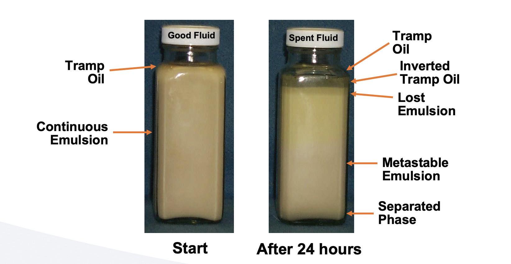 Figure 27. Basic demonstration of MWF stability.
MWF concentration
Some MWFs have 20 or more components, so to know the actual concentration of each ingredient would be time consuming and costly. However, there are basic ways to determine effective methods to measure MWF concentration for a metal-removal operation
(see Table 10).
Table 10. MWF concentration measurement methods.
Conclusion
MWFs play a vital role in the machinery of metal products. However, they are composed of a range of chemical constituents, which make them vulnerable to numerous failure mechanisms. It is critical to understand the most common failure mechanisms discussed in this article as well as the most effective ways to combat them.
REFERENCE
1.
Agapiou, J. S. (2018), “Performance evaluation of cutting fluids with carbon nano-onions as lubricant additives,”
Procedia Manufacturing, 26, pp. 1429-1440.
Dr. Yulia Sosa is a freelance writer based in Peachtree City, Ga. You can contact her at dr.yulia.sosa@gmail.com.