What about viscosity?
By Dan Holdmeyer, Contributing Editor | TLT Lubrication Fundamentals February 2023
Our everyday experiences can help us define and understand viscosity.
To discuss lubrication fundamentals, we must talk about viscosity. It is the most important characteristic of a lubricant. It is the lubricant’s resistance to flow. But what is it really?
We do have routine experiences that demonstrate viscosity variations. We can tell water flows quickly, demonstrating its low viscosity. We may call water “thin” relative to maple syrup, which doesn’t flow so freely. The more viscous syrup may be considered “thick.” Yet, under the right conditions, water can lift your car off of the road. Remember hitting a water puddle at speed resulting in your car hydroplaning? Hopefully you slowed down and the car regained contact with the road.
Simply stated, viscosity (V) is equal to the shear force per area (F) divided by the shear rate (R).

What does that mean? I understand the equations used to measure and quantify viscosity due to my studies in the engineering discipline. However, I want to relate it in terms I experienced in my growing up on the farm in Missouri, because that is my “fallback” to understanding most things.
So, looking at Figure 1, we have two plates lying parallel to each other, completely separated by a liquid full fluid film with no plate-to-plate contact—in other words, a hydrodynamic lubrication regime. The bottom plate is stationary, and the top plate is sliding left to right. The liquid next to the sliding plate moves close to the speed of the plate while the liquid next to the stationary plate remains still. Shearing happens to the liquid layers in between the two plates. I imagine the layers of liquid in this scenario to be similar to a deck of cards.
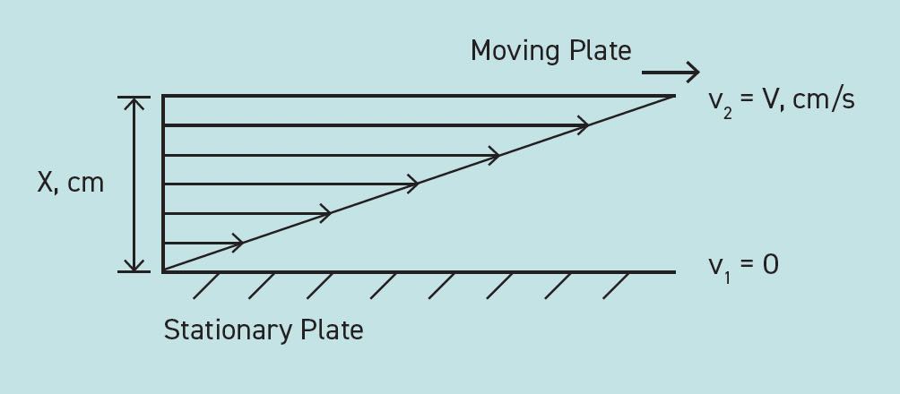
Figure 1. Simple shear example.
The rate of shear is dependent on the speed and distance between the plates.
If we increase the speed up the sliding plate, it makes sense that the rate of shear (R) in the liquid will increase. Therefore, to keep the shear force (F) constant while increasing the shear rate (R) via the faster sliding speed, we need to decrease the viscosity (V).

If we don’t decrease the viscosity, more shear force is needed to increase the speed, and that force is exerted against the liquid’s viscosity, or resistance to flow, and that increased energy results in heating the liquid, possibly overheating.
If we keep the top plate moving at the same speed and decrease the film thickness while still keeping the plates from touching each other, the rate of liquid shearing also will increase. This is because each of the fewer layers of liquid must shear farther to keep the oil next to the sliding plate moving with it and the liquid layer next to the stationary plate still. Here I imagine fewer cards in my deck of cards. Then, going back to our equation, we need to lower the viscosity of the liquid to offset the increase in shear rate so that the same force is required to move the plate at the same speed.
Part of the shear force per area mentioned previously that we haven’t talked about yet in our viscosity equation is the nominal stress besides the shear stress exerted on the plate. Normal stress is the load on, or weight of, the top sliding plate. Normal stress is the vertical downward force on the plate, or the force perpendicular to the plate. Shear stress, on the other hand, acts parallel to the plate pushing it to the right.
Therefore, going back to our viscosity equation, if we increase the shear force via added weight on the top sliding plate, we need to see an increase in the shear rate or an increase in viscosity A higher viscosity fluid will maintain the full fluid film longer keeping the plates in a hydrodynamic lubrication regime. The right viscosity is matched against the increased shear force per area.
Or we can increase the shear rate to offset the added normal stress or load, by increasing the speed to maintain a hydrodynamic film. If you do neither, don’t increase the viscosity or the speed, the separation of the two plates will diminish to increase the shear rate resulting in potential plate-to-plate contact. You noticed this when your car hydroplaned going through a water puddle at speed, and when you slowed your automobile, your tire and the road made contact again.
Now that we’ve qualified our viscosity equation, we should quantify viscosity. First, let’s look at how viscosity is measured. There are a myriad of viscosity measurements and classifications. Redwood Number, Degrees Engler, Saybolt Universal Seconds (SUS), centiStokes (cSt) and centiPoise (cP) are some units of viscosity, with cSt and cP being the most common today. Viscosity classifications commonly used in North America are International Organization of Standards (ISO) viscosity grades, Society of Automotive Engineers (SAE) J300 for engine oils and SAE J306 for automotive gear oils and American Gear Manufacturers Association (AGMA) 9005.
International Standards defines viscosity as absolute viscosity (also called dynamic viscosity) reported in cP and kinematic viscosity reported in cSt. Absolute viscosity is a measure of a fluid’s internal resistance to flow, whereas kinematic viscosity is the absolute viscosity relative to the fluid’s density, or specifically, the kinematic viscosity equals the absolute viscosity divided by the fluid’s density.
Most mineral oils have a density of approximately 0.9. Therefore, when converting from kinematic to absolute viscosity, multiply the kinematic viscosity by 0.9 to get the absolute viscosity. The difference for practical purposes is minimal; however, in applications where very precise viscosity measurements are critical, the absolute viscosity is used. This reminds me of the philosophical question: “If when approaching a wall, each step gets you ½ the distance closer to the wall, do you ever reach the wall?” In a practical sense, yes you do reach the wall, whereas in precise terms you will never reach the wall. Since this is a Lubrication Fundamentals article, we’ll be comfortable with interchanging absolute and kinematic viscosities in our applications.
Kinematic viscosity is often measured via U-tubes in a controlled temperature bath. A specific quantity of oil is drawn up one side of the U-tube, and the time required for the oil to flow through an orifice in the U-tube is noted. Each tube is calibrated to convert the noted time to kinematic viscosity (see Figure 2). The oil the bath temperature is typically set at either 40 C or 100 C and, thus, the viscosity is reported as cSt at 40 C, or cSt at 100 C, respectively. Kinematic viscosity times the oil density equals the absolute viscosity.
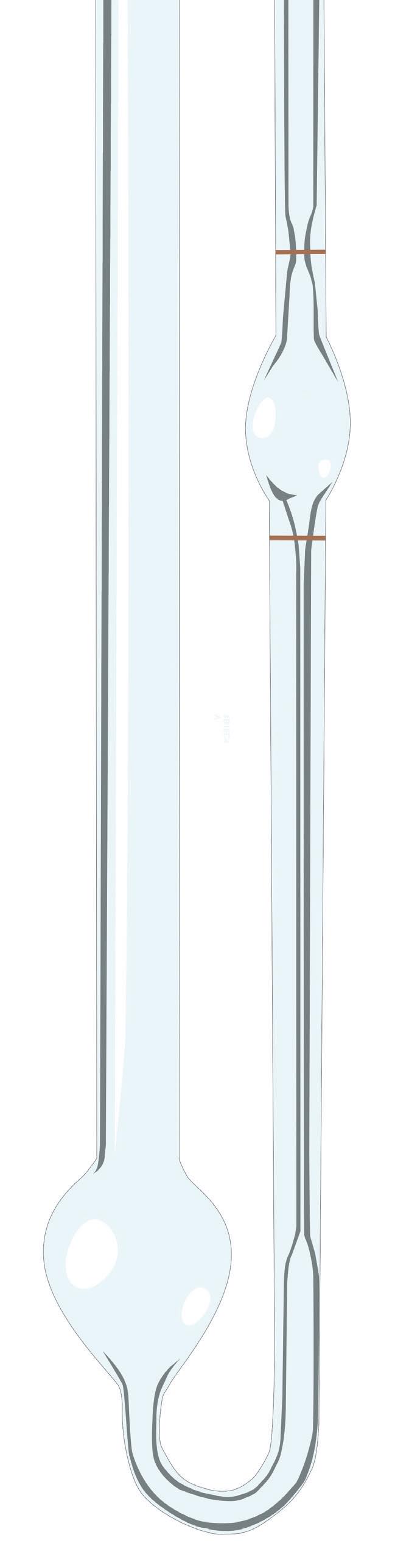
Figure 2. Simple illustration of a viscometer.
Prior to switching to the International Standards (SI) units, kinematic viscosity was reported in SUS at 100 F and 210 F. You may find some older machine lubrication specifications only listing SUS. You can convert SUS at 100 C to cSt at 40 C by dividing the SUS units by 5 to get cSt units. This rule of thumb works best for oil viscosities between 20 cSt and 1,000 cSt at 40 C. To be more precise, you may reference some lubricant suppliers’ technical data sheets that still list both units of measure, or refer to a viscosity grade comparison chart.
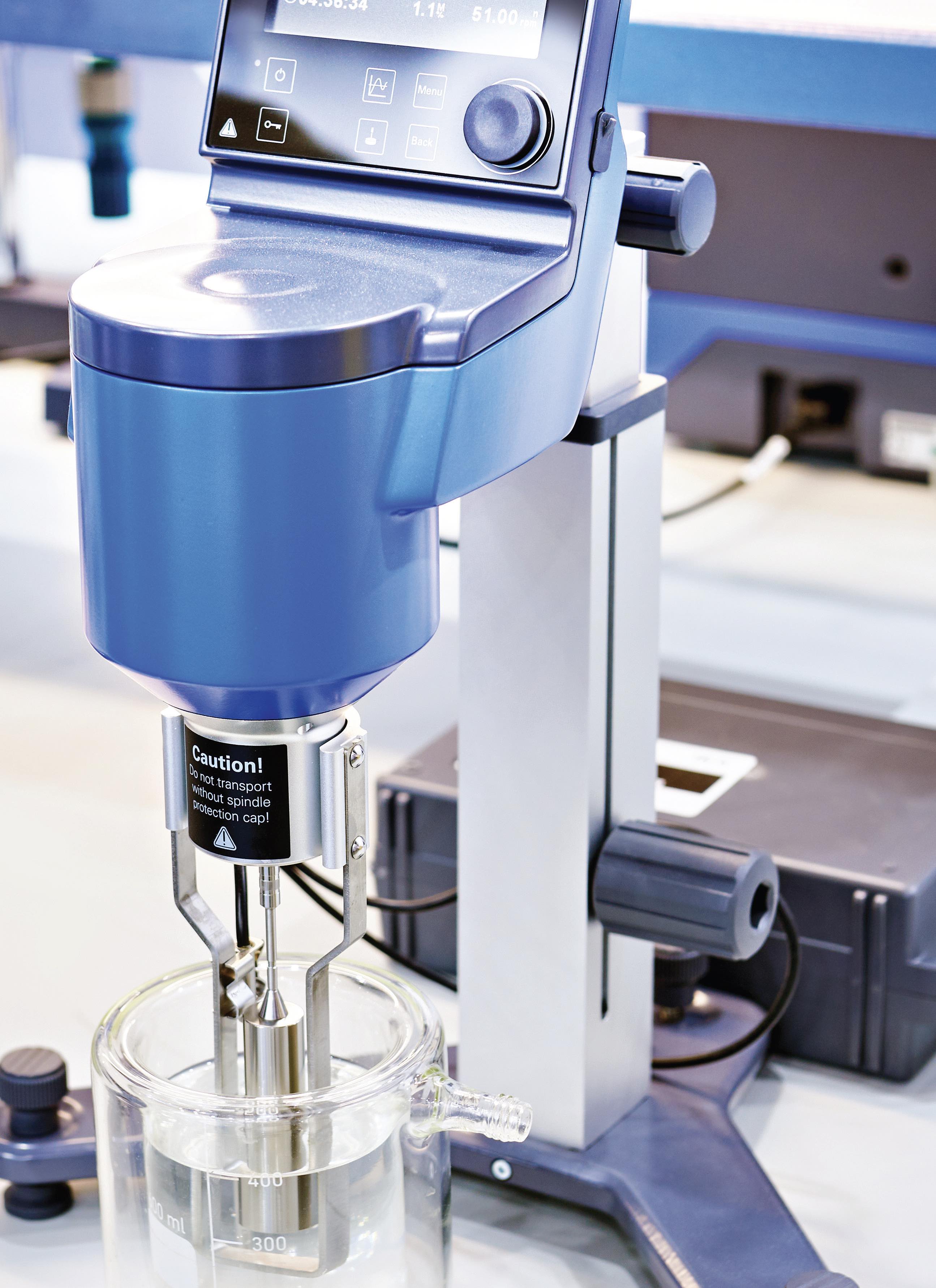
Absolute viscosity is most often measured via a mini-rotary viscometer, which is not affected by the weight or density of the liquid. The resistance to the rotation is measured and converted to cP at 40 C and 100 C, plus it can be used to determine an oil’s viscosity at extreme temperatures or when exposed to high shear rates, as in the engine piston ring and cylinder liner interface. The mini-rotary viscometer is used to measure absolute viscosity and report it in cP for critical engine oil measurements such as the cold cranking simulator (CCS) and the high temperature high shear (HTHS) specifications. At 0 F, engine oil viscosities can reach tens of thousands of seconds (SUS). Measuring the oil’s viscosity with a U-tube would be very time consuming, but the mini-rotary viscometer can measure that in minutes.
So, we have absolute viscosity and kinematic viscosity differentiated by the density of the fluid, and we measure them at specific temperatures. Measuring and reporting a fluid’s viscosity at various temperatures correctly implies viscosity is not constant over a temperature range. I first recognized this at an early age when I realized that the maple syrup when first pulled from fridge storage poured painfully slow, but when it was stored in the unrefrigerated cabinet, I was able to pour more syrup, quickly! I incorrectly thought that was unique to syrup because room temperature water poured “the same” as refrigerated water. However, water viscosity does change with temperature but not nearly as dramatically as syrup.
That viscosity change with temperature is given a value called viscosity index and is calculated using the viscosity of the fluid at the standard temperatures noted previously and referencing those against the viscosities of two reference fluids. Counterintuitively, the higher the viscosity index, the less the viscosity changes with temperature. We do not have space to detail viscosity index calculations in this article, but we will tackle that next month.
Not counterintuitive, but maybe more of a misleading name, is the SAE naming protocol for multigrade engine and gear oils. An SAE 10W-30 motor oil has the viscosity of an SAE 10W at low cold starting temperature and the viscosity of an SAE 30 at the high operating temperature, and yet the oil’s viscosity does decrease with increasing temperature.
So next month, we will discuss viscosity index calculations, viscosity grade classifications and this multigrade automotive oil conundrum.
Dan Holdmeyer is retired from Chevron Lubricants and is based in Washington, Mo. You can reach him at dan.holdmeyer@gmail.com.