Air mist lubrication
By Dan Holdmeyer, Contributing Editor | TLT Lubrication Fundamentals January 2023
A properly installed and maintained oil mist system consistently delivers the right amount of the right lubricant at the right time.
Lubrication systems vary greatly depending on budget and system requirements. Circulating systems and bath or splash lubrication methods reuse the initial charge of lubricant to lubricate various components within the system. Hand oil cups, bottle oilers and mechanical force feed lubricators fall into the “all loss” category. Grease may be applied via bath as in a slow rotating gear set, but most grease applications also are all loss systems, whether it is a grease gun supplying grease via a zerk, a single point automatic grease lubricator or an automatic lubrication system feeding a myriad of lubrication points.
Let’s talk about a couple of other all loss oil systems, specifically air-line oilers and oil mist systems.
Air-line oilers are primarily used for relatively light-duty pneumatic actuators, linear actuators (air cylinders) and rotary actuators (handheld drills, wrenches and drivers). Since these are light-duty applications, low viscosity (ISO VG 46 or lower) rust and oxidation inhibited oils are used in these applications. The air-line lubricator is attached to a compressed air supply and placed close to the pneumatic device to minimize the amount of oil that may drop out of the air stream before it reaches the pneumatic device. The lubricators are adjusted to provide the minimum amount of lubricant needed by the equipment to avoid excess oil being blown out into the immediate environment. Air-line lubricators have three primary components placed in the following order: 1.) filter to remove particulate and water from the air supply, 2.) regulator to control the air flow amount and 3.) lubricator to suspend an adjustable amount of oil droplets in the air.
Oil mist systems also may be called by other names, such as “mist oil,” “meter-mist” or “micro-fog.” Oil mist systems have a few differences from air-line lubricators. One oil mist system usually lubricates multiple points, whereas the air-line oilers are dedicated to one pneumatic device. The oil is misted into the air at a convenient location and is then piped to multiple locations. Because the oil-air mist must travel some distance, the oil droplets need to be smaller to minimize the amount of oil that condensates out in the piping. Furthermore, oil mist systems are used for various types of applications, sizes and severity, thus requiring different lubricants.
Developed in the early to mid-20th century, oil mist systems were first developed to solve high speed bearing lubrication problems where then existing grease and oil systems were not successful. Applications expanded from bearings operating at 100,000-plus rpms to heavily loaded metal rolling mill bearing loaded to 2,000-plus tons, and to gears, cams, chains and sliding surfaces of machines in steel, paper, construction and an increasing range of other industries.
It stands to reason that because oil mist systems serve such a variety of industries and applications, each system’s applications must be surveyed to determine the appropriate lubricant for the applications lubricated. The oil mist system does not dictate the lubricant to use; the applications lubricated by the oil mist system influence the lubricant selected. Electric motor or compressor bearings may require an ISO VG 46 rust and oxidation (R&O) oil. Gears may require an anti-scuff, or R&O, oil of ISO VG 150, 220, 320, 460 or higher. Depending on the complexity of the applications, more than one oil mist system may be used in an area, and each may require a different lubricant, and this may be misunderstood by operators and maintenance personnel.
The oil mist generator, as does the airline oiler, creates the oil mist by sending pressurized air through a venturi or vortex to drop the air pressure in the line to draw the oil in to the air stream. The high velocity of the air mechanically breaks the oil into droplets of various sizes. The larger droplets are removed from the air stream so they do not drop out in the piping, which may cause system failure. Most generators have oil and air heaters to help “atomize” the higher viscosity oils.
Let’s look at the operating principle of mist oil lubrication to help understand the oil mist system.
The principle of oil mist lubrication is that oil droplets coalesce by impact against a surface at high velocity. Think of using cooking oil spray from an aerosol can. When the nozzle is directed at the cooking pan, liquid oil will coalesce, or collect, on the pan. More oil will be coalesced by locating the nozzle closer to the surface because the impingement velocity is increased. The higher impingement velocity coalesces more of the smaller droplets. The larger droplets require less velocity to coalesce, or to “reclassify,” as is the term used in oil mist lubrication.
Therefore, in the oil mist generator, a baffle is placed downstream from the vortex or venturi so that the larger droplets impinge against it and drop out of the air stream and back into the generator reservoir. Generally, droplets of 6 micron in diameter begin to reclassify at a velocity of about 25 feet per minute, whereas a droplet of ½ micron size doesn’t reclassify under 5,000 feet per minute impingement speed. Thus, the oil droplets in the air flowing through the piping end up being smaller than 4 microns and are carried hundreds of feet of piping to the lubrication points, so long as the air velocity does not exceed 24 feet per minute and remains laminar in flow.
Piping design and layout also are critical in an oil mist system to minimize oil coalescing before reaching the lubrication points (see Figure 1). Recommendations vary, but the first 10 to 50 feet of piping are sloped down back toward the oil mist generator, so any of the larger droplets that may coalesce there are returned and don’t get trapped somewhere in the piping. Sharp turns are avoided in the piping as they create impingement opportunities to coalesce oil in the lines. Dips in the lines also are avoided to prevent any coalesced oil from being trapped. Pipes to lubrication points are connected to the main pipe line on the top side of the main pipe to eliminate coalesced oil from the lube point pipe.
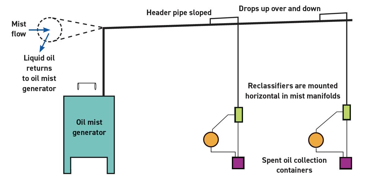
Figure 1. Oil mist lubrication system with piping.
Finally, the oil mist reaches the lubrication point where coalescing or reclassifying is required to “wet” the metal surfaces. Different reclassifiers are used for different applications. High speed rolling element bearings create enough impingement velocity with the oil mist so that no coalescing assistance is needed for the oil to reclassify and wet the bearing. Journal bearings or slides require a condensing fitting with a high degree of coalescing completeness to wet the metal surfaces. An intermediate amount of coalescing from a spray type reclassifier may be used on gears, chains and slower rolling element bearings.
There are several benefits realized from a properly installed and maintained oil mist system. The right amount of the right lubricant is consistently delivered at the right time. The oil is ultra-pure because the oil droplets are generally less than 4 microns in diameter, thus there is no large particulate matter in the lubricant. The positive air pressure excludes water and particulate contamination at the lubrication point, and bearings typically run about 10 C cooler. Finally, less manpower and probability of human error can be realized for lubrication; however, that does not mean set it and forget it. The principle of oil mist lubrication is that oil droplets coalesce by impact against a surface at high velocity.
Most, but not necessarily all, units have alarms and light indicators when in need of maintenance, but there are several items that need routine maintenance. Many systems have dead leg sump bottles at the end of lube point rows and low points in the piping to collect condensed oil that need to be drained to not allow oil levels to get so high as to interfere with the oil mist reaching the lubrication points or possibly backing up into the lubrication points. These dead leg bottles do not have alarms. The unit heater usually has alarms, but if the oil gets cold it coalesces early and disrupts the system. An obvious maintenance step is to keep the oil mist generator reservoir filled with the right lubricant. This may be missed because of the infrequency required if the unit does not have an alarm, or the alarm is ignored or shut off.
Besides reclassification, other oil mist system terms include “mist ability,” or the ability of the oil to atomize in the system, and “stray mist,” which is an environmental hazard to be monitored. Occupational Safety and Health Administration (OSHA) has set maximum exposure limits for a person over an established period of time. Vents are used at lubrication points to collect stray mist that is not reclassified. Some mist oils claim special additives to improve atomization and reclassification.
With a bit of knowledge on oil mist systems fundamentals, maintenance and operation of a properly installed system is simple and valuable in maintaining equipment reliability.
Dan Holdmeyer is retired from Chevron Lubricants and is based in Washington, Mo. You can reach him at dan.holdmeyer@gmail.com.