Afton Chemical Corporation
Global Trends in Drivetrain Development and Associated Technologies
Introduction by Alyson Wilson, Marketing Manager-Industrial, Afton Chemical Corporation
Article by Kiran Govindswamy and Thomas Wellmann, FEV North America, Inc. | TLT CMF Plus November 2022
Introduction
In this article, Afton Chemical’s Key Driver Seminar guest speakers from FEV North America discuss how the automotive industry continues developing new powertrain and vehicle technologies to reduce overall vehicle-level fuel consumption. Specifically, innovative powertrain and drivetrain technologies, including conventional and electrified propulsion systems, are expected to play an increasingly significant role in helping OEMs meet the required fleet CO2 reduction targets for the coming decades.
Market Trends
Market forecasts signal a significant increase in shares of pure electric vehicles (EV) and hybrid electric vehicles (HEV), making electrification the most significant megatrend in vehicle propulsion technology. For achieving CO2 fleet targets for passenger vehicles, high growth rates for electrification of powertrains are expected, resulting in a strong demand for EDUs. In recent years the trend has further accelerated, with an even larger expected growth of electrification share in propulsion systems.
EDU Trends and Influence on Fluids and Lubricants
Electric drive units combine electric motors, power electronics, and reduction gear(s) into the vehicle’s propulsion system. While these components were only semi-integrated for the first-generation drive units, the trend is increasingly moving towards fully integrated units, where all components of the drive unit are combined in a single housing. These drive units utilize common cooling and lubrication systems, which may negate the system’s need for water/glycol cooling, as illustrated in Figure 1. The combination of cooling and lubrication functions, contact of the fluid with copper, and the use of highspeed electric motors result in stringent requirements for the fluid used in electric drives. Figure 2 illustrates key technical requirements for the fluid, driving the desire for E-fluid-specific development.
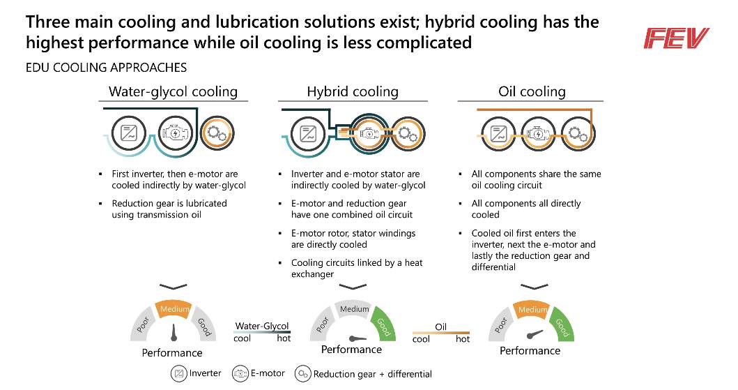 Figure 1: Cooling and lubrication solutions.
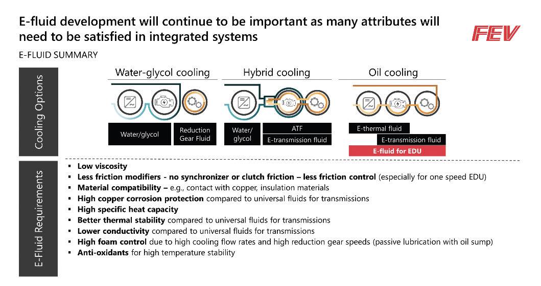
Figure 2: E-fluid requirements.
With respect to EDU development, as well as fluid development for drive units, simulation tools are an important enabler. Simulation-based methodologies allow for the development of concept designs that are initially optimized without available hardware; such approaches are utilized for finding the most suitable compromise for potential target conflicts. In addition, overall development time and the number of prototype builds can be reduced with the efficient utilization of simulation-based methodologies. Figure 3 gives an example of computational fluid dynamics (CFD) simulation for a single-speed geartrain. In this case study, both drag loss of the geartrain and lubrication flow to all moving parts were investigated and optimized. Different fluid values, such as viscosity, can be used in these models for fluid-related evaluations. For testing-based validation, it is necessary to have access to test sites with fluid-conditioning systems, dynamometers, high voltage battery emulation systems, and high-accuracy measurement equipment that can all be utilized to ensure accurate and repeatable results [Figure 4].
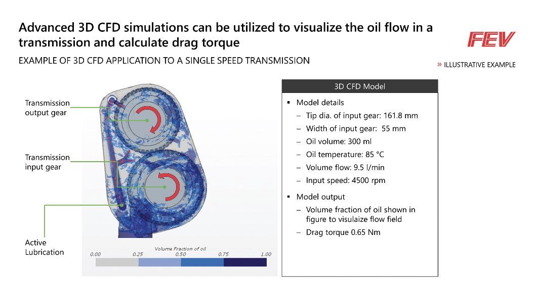 Figure 3: CFD example of oil flow and drag loss.
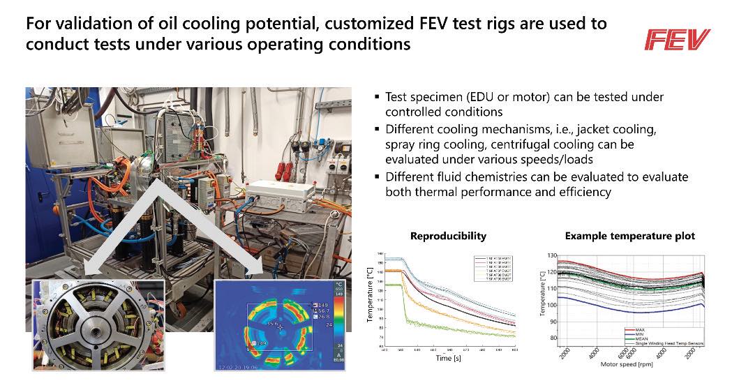
Figure 4: Component validation test example.
Heat transfer capabilities is one of the key aspects for E-fluid development. Electric motor efficiency decreases with hot temperatures generated by the current within the copper coils. Furthermore, motor protection must be assured as components can be permanently damaged when exceeding specific temperature limits. The power of the drive unit is typically de-rated under constant high load to prevent potential overheating. With increased motor cooling and better cooling performance of the fluid, this practice can be delayed or avoided altogether, resulting in improved vehicle performance. An example of heat transfer testing with different fluids on an electric motor test setup is shown in Figure 5.
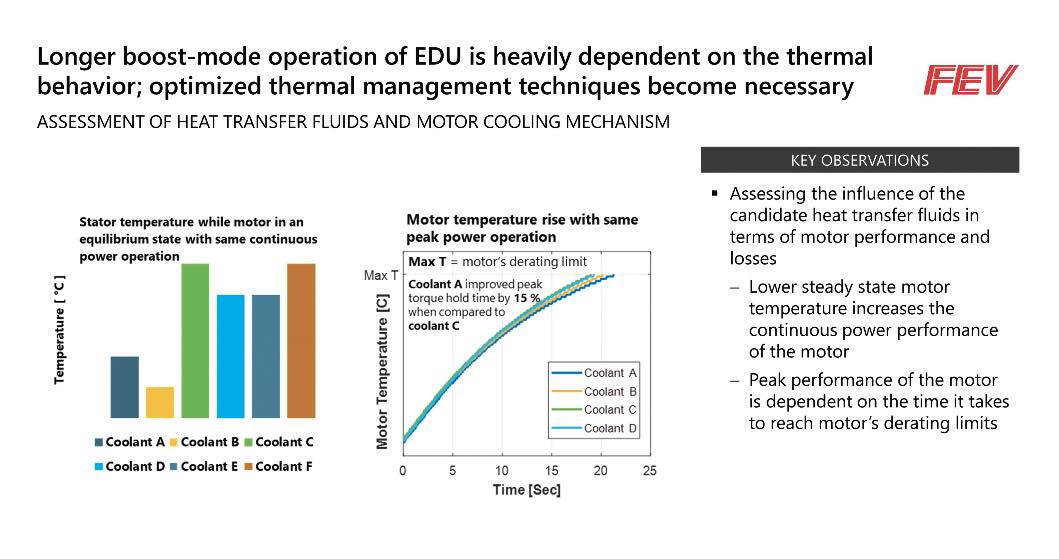 Figure 5: Motor heat transfer testing.
Another important aspect for the overall vehicle efficiency and waste-heat minimization is the “right-sizing” of the electric motor. Motor torque and power are determined by vehicle and drive unit requirements and depend on vehicle size, weight, and application. High-performance motors are desirable for high-performance vehicles but are often not within their most efficient range when operated under normal driving conditions that are more relevant for vehicle range determination [Figure 6]. Multi-gear drive units can help move the operating points of the motor towards its most efficient operational zones to find a good compromise between high torque- and high-speed operation. As multiple gears lead to higher parasitic losses due to the added moving parts in the gearbox, simulation tools in the early phases of EDU/vehicle development can help to find the best technical solution. The cost of the unit must also be assessed in the decision matrix during the vehicle concept phase. Simultaneously, a thermal management concept is developed during this period.
Figure 5: Motor heat transfer testing.
Another important aspect for the overall vehicle efficiency and waste-heat minimization is the “right-sizing” of the electric motor. Motor torque and power are determined by vehicle and drive unit requirements and depend on vehicle size, weight, and application. High-performance motors are desirable for high-performance vehicles but are often not within their most efficient range when operated under normal driving conditions that are more relevant for vehicle range determination [Figure 6]. Multi-gear drive units can help move the operating points of the motor towards its most efficient operational zones to find a good compromise between high torque- and high-speed operation. As multiple gears lead to higher parasitic losses due to the added moving parts in the gearbox, simulation tools in the early phases of EDU/vehicle development can help to find the best technical solution. The cost of the unit must also be assessed in the decision matrix during the vehicle concept phase. Simultaneously, a thermal management concept is developed during this period.
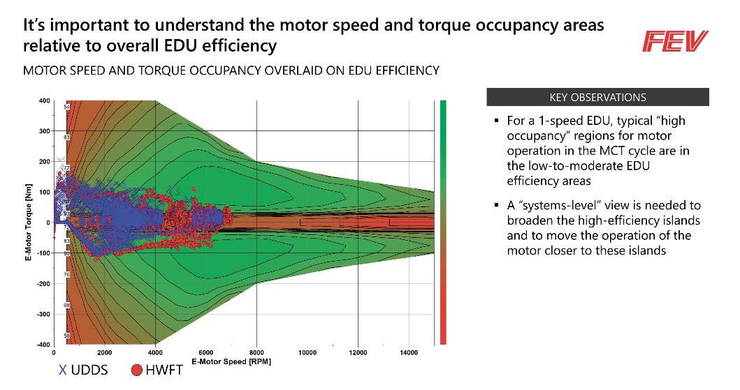 Figure 6: Motor efficiency range vs. operation range.
Thermal Management Development Process
New purpose-built BEV platforms are becoming increasingly common. Historically, electric vehicles were often derived from conventional vehicle architectures.
For dedicated electric vehicles, the former compartment of the internal combustion engine can be significantly reduced, re-purposed, or even eliminated, leaving more interior room and space for the battery while yielding a vehicle with similar outer dimensions. Package concepts and constraints can be vastly different for dedicated battery electric vehicles. For these new vehicle architectures, in the “skateboard chassis”, which is frequently employed, the EDU packageability, as well as thermal management components change noticeably. Each of the key components of the vehicle propulsion system, such as the battery, motor, power electronics, and gearbox, has its own thermal requirements and optimal temperature range. For example, batteries tend to perform best in a small temperature window of approximately 20-35°C, while gearbox oil for single-speed electric drives is usually in the 40-60°C range during normal operation and can even get higher at high load operation. For minimizing unwanted waste-heat (and hence improving efficiency), thermal management becomes important for increasing electric drive range without increasing the battery capacity (and therefore weight and cost). Additionally, impacts on climate control for the passenger compartment must be considered as they are an important part of thermal management and critical for both passenger comfort and safety features such as window defogging.
All vehicle aspects can influence thermal management: Vehicle architecture, packaging, aerodynamics, styling, passenger comfort, and key powertrain and battery considerations all influence the overall thermal behavior and energy efficiency of the vehicle. Thermal management software and control functions must be developed and tested to optimize each of these areas.
The vehicle’s energy management should be developed and understood using a full systems approach. Figure 7 provides a high level of main steps and key contributors that must be included in the vehicle’s energy management development process. In addition to the vehicle and component hardware, software and controls for active thermal management become essential. Progression of both the hardware and software must start at the vehicle concept phase and follow the entire development process through the start of production. The key steps in the thermal management development process are outlined in Figure 8.
Figure 6: Motor efficiency range vs. operation range.
Thermal Management Development Process
New purpose-built BEV platforms are becoming increasingly common. Historically, electric vehicles were often derived from conventional vehicle architectures.
For dedicated electric vehicles, the former compartment of the internal combustion engine can be significantly reduced, re-purposed, or even eliminated, leaving more interior room and space for the battery while yielding a vehicle with similar outer dimensions. Package concepts and constraints can be vastly different for dedicated battery electric vehicles. For these new vehicle architectures, in the “skateboard chassis”, which is frequently employed, the EDU packageability, as well as thermal management components change noticeably. Each of the key components of the vehicle propulsion system, such as the battery, motor, power electronics, and gearbox, has its own thermal requirements and optimal temperature range. For example, batteries tend to perform best in a small temperature window of approximately 20-35°C, while gearbox oil for single-speed electric drives is usually in the 40-60°C range during normal operation and can even get higher at high load operation. For minimizing unwanted waste-heat (and hence improving efficiency), thermal management becomes important for increasing electric drive range without increasing the battery capacity (and therefore weight and cost). Additionally, impacts on climate control for the passenger compartment must be considered as they are an important part of thermal management and critical for both passenger comfort and safety features such as window defogging.
All vehicle aspects can influence thermal management: Vehicle architecture, packaging, aerodynamics, styling, passenger comfort, and key powertrain and battery considerations all influence the overall thermal behavior and energy efficiency of the vehicle. Thermal management software and control functions must be developed and tested to optimize each of these areas.
The vehicle’s energy management should be developed and understood using a full systems approach. Figure 7 provides a high level of main steps and key contributors that must be included in the vehicle’s energy management development process. In addition to the vehicle and component hardware, software and controls for active thermal management become essential. Progression of both the hardware and software must start at the vehicle concept phase and follow the entire development process through the start of production. The key steps in the thermal management development process are outlined in Figure 8.
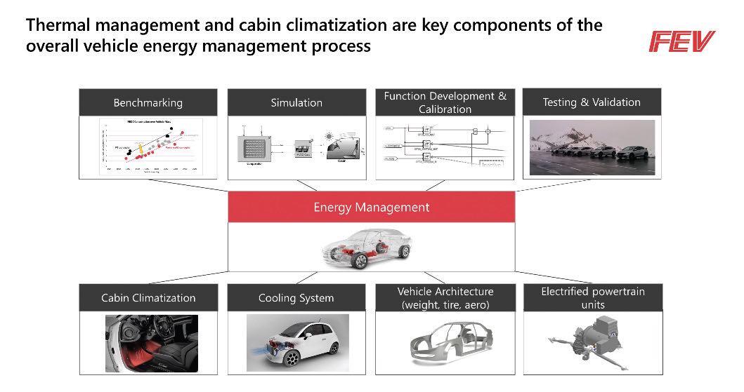 Figure 7: Aspects of the thermal management process.
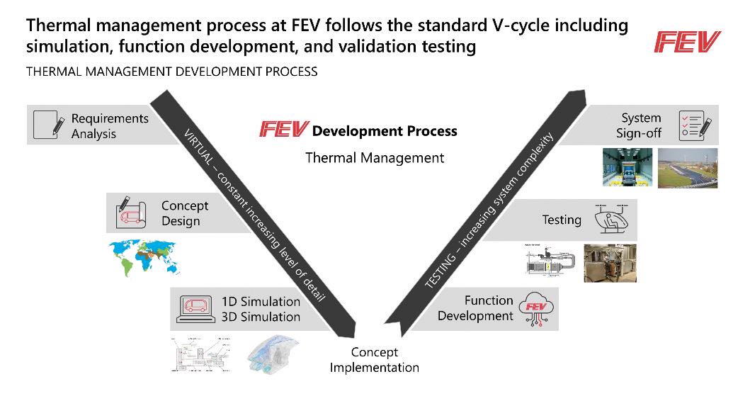
Figure 8: Thermal management development process.
An example of the importance of simulation in developing active thermal management strategies is shown in Figure 9. While closing active grill shutters can improve the aerodynamic drag of the vehicle (and hence reduce the driving resistance), it can lead to reduced cooling and associated higher operating temperatures of the electric motor in the drive unit, resulting in higher electrical losses in the motor. This relatively simple case study illustrates the complexity of thermal management and demonstrates the need for enhanced simulation methods for thermal loss optimization.
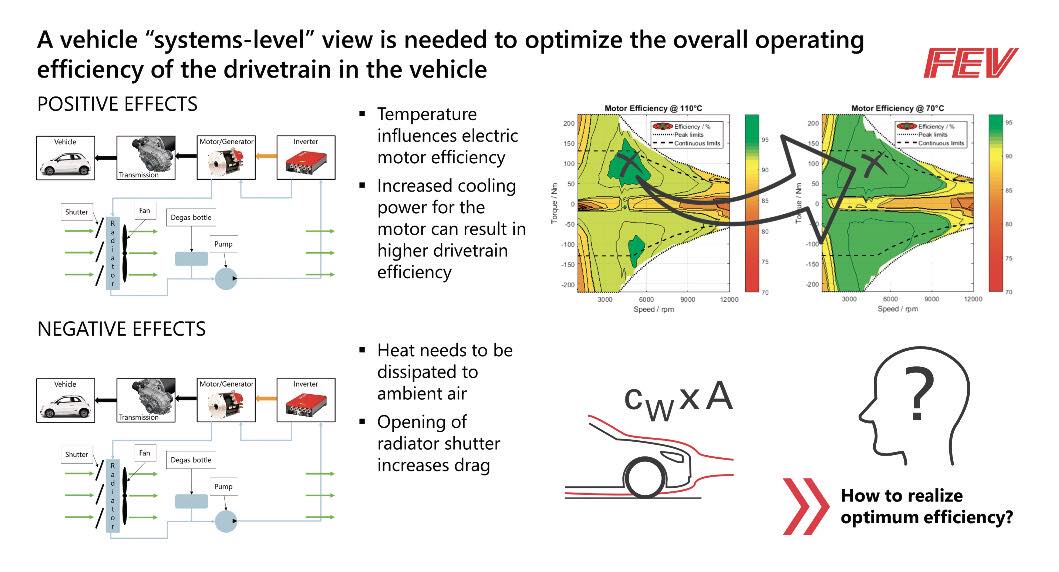 Figure 9: Example of a systems-level view on thermal management.
For full vehicle thermal management and optimizing the interaction of all components, simulation and testing of the vehicle are vitally important. One method often applied for this process is determining the energy flow during a given drive cycle. A simulation model is developed and correlated to measurement results in this process. Measurements include multiple parameters; some examples would be mechanical power measured via rotational speed and torque values, electrical powers measured via voltage and current, or thermal heat transfer measured via flow and temperature measurements. Once the simulation is correlated with measurements on a drive cycle, other cycles can be simulated. Furthermore, the model allows for parameter studies to optimize all the vehicle sub-systems from an operational efficiency standpoint. The energy flow results are often graphically shown in Sankey diagrams; Figure 10 gives an example of a process applied on a power-split hybrid vehicle.
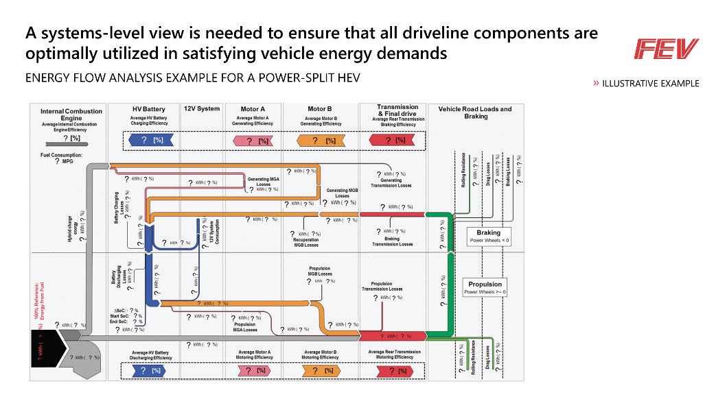 Figure 10: Sankey diagram example.
Summary
The industry faces multidimensional challenges from legislative, economic, and societal perspectives. Technical solutions must satisfy all these requirements to succeed in the marketplace. Drivetrain technologies to meet future requirements are either already available or under development. However, different markets have different requirements, and hence multiple technical solutions will co-exist as a matter of practicality. Drivetrain lubrication and heat transfer needs will evolve as the quest to optimize electrified drivetrain systems’ efficiency continues.
When developing an effective thermal management strategy, it is important to do the following:
• Employ advanced analyses to optimize the design for low-loss potential
• Conduct detailed bench tests in controlled environments to minimize fluids-related losses
• Develop thermal management strategies and controls functions to offer full systems level optimization potential
• Utilize vehicle-level energy flow assessments to optimize the operational efficiency of drivetrain components via thermal management and modified controls/calibration strategies
Figure 10: Sankey diagram example.
Summary
The industry faces multidimensional challenges from legislative, economic, and societal perspectives. Technical solutions must satisfy all these requirements to succeed in the marketplace. Drivetrain technologies to meet future requirements are either already available or under development. However, different markets have different requirements, and hence multiple technical solutions will co-exist as a matter of practicality. Drivetrain lubrication and heat transfer needs will evolve as the quest to optimize electrified drivetrain systems’ efficiency continues.
When developing an effective thermal management strategy, it is important to do the following:
• Employ advanced analyses to optimize the design for low-loss potential
• Conduct detailed bench tests in controlled environments to minimize fluids-related losses
• Develop thermal management strategies and controls functions to offer full systems level optimization potential
• Utilize vehicle-level energy flow assessments to optimize the operational efficiency of drivetrain components via thermal management and modified controls/calibration strategies
Source: FEV © by FEV – all rights reserved. Confidential – no passing on to third parties.