KEY CONCEPTS
•
Gear interfaces are a complex area of tribology and require a number of considerations when designing and monitoring.
•
End-users can choose from a range of tools, from numerical to computational, that aim to reduce gear failures.
•
Gear lubrication and gear dynamic modeling are currently separated. Integrating these approaches in the future could lead to a more systematic design for better gear performance.
Evidence for the production of toothed wheels, better known as gears, can be traced back as early as the 3rd Century BCE.
1 Over time, through both mathematical modeling and trial and error, the complexity and sophistication of gear systems increased, leading to innovations in complex machinery, astronomy and computing. Today, gears are used in numerous applications, from the small planetary gearboxes in hand drills to the meter- wide gears in windmills to vehicle transmissions and, more recently, engine gearboxes.
Contacting gear teeth represent one of the most complicated areas of tribology. As a result, there are many ways gears can fail. Methods to prevent, predict and understand gear failure have improved in part due to advances in computing power, but simpler, more accessible approaches also are available. Identifying the best tools to assess performance problems in gears requires an understanding of the functional requirements of a given application as well as the ways in which gears can fail.
Why do gears fail?
From a tribology standpoint, gears have a number of major modes of failure that can result from lubrication inadequacy, flash temperatures and contact stresses. Understanding the factors that contribute to each kind of failure provides end-users with a path toward predicting and avoiding these failures.
Surface pitting
Even the smoothest materials have rough surfaces at the microscopic level, including gear teeth. If the lubricating film doesn’t maintain sufficient thickness between gear teeth, points of stress can concentrate at these protruding microscopic surface irregularities, called asperities, or on surface material defects, which may result in the formation of fatigue cracks along and just below the surface of the teeth. This cracking, which can propagate along the tooth surface, can cause the formation of micrometer-sized pits, a process called micropitting. The use of low-quality material or contaminated lubricant can increase the likelihood of micropitting, also sometimes referred to as gray staining or frosting because of the altered tooth surface appearance.
Areas of micropitting frequently accelerate wear, which leads to a loss of the tooth profile and stress concentrations at the edge of the wear areas. When a micropit grows large enough or several pits combine, a more severe pit known as a spall can form. This process is referred to as macropitting and can lead to a catastrophic gear failure, potentially causing disruptions in goods or services production as well as high repair costs. Another source of macropitting is inclusions in the gear-tooth material where stress can concentrate. The presence or absence of these inclusions are dictated by the metallurgy and processing of the gear material.
The portion of the tooth below the midpoint, called the dedendum, as well as the pitch line of the tooth, are at risk for micropitting. Two points that are particularly vulnerable are the start of the active profile and the lowest point of single tooth contact (LPSTC), but micropitting can occur anywhere on active flanks.
Wear
“If you don’t fail that gear by the tooth fracture, the next mode of failure is going to be tooth surface deterioration,” says STLE Life Member Vern Wedeven, founder of Wedeven Associates. Gears and gear systems are expected to last for thousands of hours, so manufacturers design and fabricate gears to resist wear and other forms of surface deterioration. But depending on the operating conditions, surface deterioration can be accelerated. Wear can be caused by surface fatigue—as well as adhesion, abrasion and corrosion. Failure analysis frequently reveals that surface deterioration occurs through a combination of processes involving wear, adhesion and fatigue mechanisms. While the final failure mechanism frequently takes the blame, the preceding events are usually the root cause.
Scuffing
Scuffing is an extreme mode of gear failure in which high temperatures and excessive sliding cause the gear tooth surface to pierce through the lubrication layer and make direct contact with each other
(see Figure 1). When gear teeth mesh without the protection of a surface film, asperities can deform, smear or locally weld together. Christopher Cooley, assistant professor in the School of Engineering and Computer Science at Oakland University, says, “When you get metal-to-metal contact, you’re going to mechanically alter the profile of the tooth surface and modify it in a way that you don’t want. You want an involute tooth surface.” Because the involute shape of gear teeth is essential to their operation, scuffing can accelerate tooth wear and lead to seizing of the sliding pair.
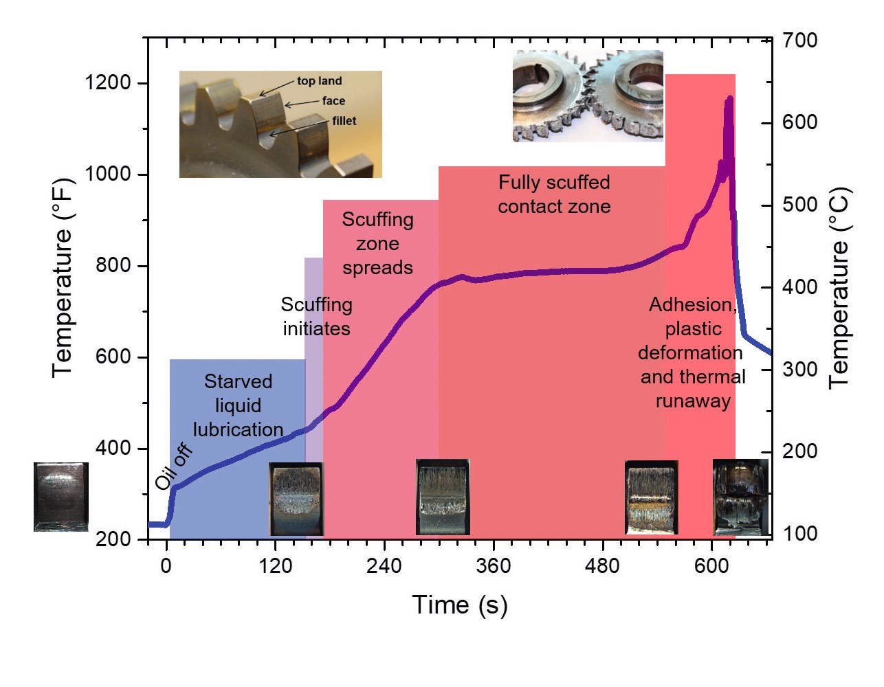 Figure 1. In high-speed spur gears subjected to a loss of lubrication, the temperature measured just outside of the mesh point of the gears reveals different stages of failure from starved liquid lubrication, through scuffing, to large-scale thermal runaway. Figure courtesy of Stephen Berkebile.
Scuffing tends to occur more often in gears that run at high speeds and temperatures, generally near the tip or the root of the tooth where the slide-to-roll ratio is usually the highest.
Benefits of modeling
Gear designers implement modeling tools to increase productivity, decrease costs and predict failure modes as well as reduce the need for extensive testing. “The models are really there to help optimize the design and the design process, so that you end up with minimal testing and minimal design risk,” says Wedeven. He outlines four main areas where modeling can help end-users predict performance.
The first is focused on noise, vibration and harshness (NVH), particularly in cars and trucks. These characteristics are related to gear tooth dynamics. Modeling and other tools can help reduce NVH for better consumer experiences and to reduce external or drive-by noise.
The second area modeling tools can aid in gear design is in understanding tooth bending. When gear teeth transmit power, they repeatedly bend, which can cause fatigue and cracking.
Understanding the behavior
Wedeven refers to the third area as gear mesh contact or gear mesh interfacing. “This includes a combination of very complex rolling and sliding motion. How that gear tooth profile is designed, along with the number of teeth selected, makes an enormous amount of difference.” He says these design factors will define the motions, stresses and temperatures of the operating interface, which ultimately will determine the life, durability and efficiency of the gear system. Controlling these features requires tribology engineering of the interface by taking into consideration and balancing the inherent rheology and chemistry of the lubricant; the strength and thermal-mechanical properties of the bounding surfaces; the surface films created during operation from reactions between the oil chemistry and surface chemistry; and the surface geometry, roughness and texture, collectively known as the surface topography. “The designer has an enormous challenge accommodating extreme interface operating conditions found in high-performance mechanical systems,” says Wedeven. Modeling here can help designers better understand how the two gear surfaces will interact.
The fourth area encompasses the supply and distribution of the lubricant. Oil losses due to viscous churning of the lubricant lead to lower efficiency and increased heat generation. Because of this, thermal analyses are a key part of modeling. “There is a delicate balance and also conflicting requirements associated with oil supply and distribution for lubrication and cooling functions. Modeling tools for viscous losses and thermal management are essential,” says Wedeven. Tools to predict oil churning losses, frictional heat generation at the contact interfaces and thermal dissipation for controlling temperature are essential.
STLE Life Member Q. Jane Wang, professor of mechanical engineering in the McCormick School of Engineering at Northwestern University, says that because gears are supported by shafts and bearings and are often mounted to larger machines or vehicles, gears are subjected to dynamic loading and impact, as well as a wide range of operating conditions and work environments. System dynamics (e.g., dynamic loading due to shaft deflection or the behavior of the bearings) influence the tribological interfaces of the interacting gear teeth, since their lubrication is dependent on how the gears contact each other as well as their relative motion. Wang says gear lubrication is, therefore, subjected to dynamic loading and transient speeds, oil churning or spray, system heat transfer, contact distribution, surface topographic conditions, tooth wear and flash heating.
With such a complicated system, modeling offers a way to choose the best lubrication method, gear geometry design and condition monitoring, as well as to determine if the gear materials or surface finishing need to be modified for better performance.
Gear lubrication modeling
Understanding the behavior of lubrication between tooth pairs with elastic contacts is essential in predicting gear tooth performance. End-users can use gear lubrication modeling tools to help prevent overheating and failure; reduce noise, vibration, losses due to friction and wear in the design stage; as well as optimize the system for light weight, prolonged life and improved reliability.
One important tool specialists use for predicting lubrication behavior between gear teeth is mixed elastohydrodynamic lubrication (EHL) models. Under high-temperature conditions or with sufficiently high loads, or in low speed, such as during initial start-ups or shutdowns, the lubrication films can be thin, which may result in metal-to-metal contact of gear asperities. Mixed EHL models offer a way to predict the microscopic aspects of gear-tooth lubrication under these conditions.
“The mixed EHL program should be capable of taking the operating conditions from system analyses and output distributions of lubricant film thickness, contact pressure, flash temperature and near surface stresses, and it would be better if wear also is predicted,” says Wang. The information obtained can be used for gear material modification, surface finish control, gear geometry design, lubrication-method selection and condition-based monitoring.
Wang suggests finite element method software for analyzing gearbox structures and computational fluid dynamics software for understanding fluid motion and heat transfer. Mixed EHL integrated fluid dynamics and contact-mechanic models can be used for different gear materials and surfaces to both consider material elastoplasticity and wear and to understand the influences of a wide range of load-speed changes and frictional heat transfer. The integration of multiscale models can help simulate realistic operating conditions.
To effectively implement lubrication modeling as a way to understand gear performance issues, Wang says there are a number of important parameters an end-user can input into a model. These include properties of the lubricant itself—it’s viscosity and density as functions of temperature and pressure, rheology and degradation behavior—the tooth surface roughness and topography and characteristics of gear materials like elastoplasticity, creep (for polymer gears) and fatigue strength as well as gear tooth heat treatment results, coatings and defect type and distribution.
Wang says the information a user chooses to input into a model will vary depending on if their interest lies in modeling a snapshot or an operation process. For example, in analyzing a snapshot of the worst condition—which is often at the LPSTC and the area of highest sliding speed—the necessary information would include the load and its distribution, the speeds of both surfaces, the meshing geometry, properties of the materials, lubricant and surface roughness, in return for microscopic stress cycles in the contact area, the minimum film thickness, friction and the flash temperature. In contrast, analyzing the process in which the gear transitions to the worst lubrication state would involve system dynamics and oil-churning analysis.
Users can acquire many input parameters for various models by using bearing and gear codes, says Wedeven, which offer the ability to calculate the actual motion, stresses and temperatures for a given application.
Outside of or coupled with modeling, a user also can employ physical simulation testing to understand gear performance, which is often outsourced. For testing, engineers extract the operating parameters for a given application—for example, velocity, load, lubrication type and temperature—and duplicate them on machines in a laboratory setting. The testing, which may be performed on dimensionally modified machines, aims to recreate the gear contacts and wear.
Modeling and simulation testing can be applied to a system for design or performance monitoring, but there also is utility in understanding how a gear has failed. In this case, an end-user can perform a surface or failure analysis, which also can be combined with analyses with software, such as a finite element modeling tool. The failure analysis can include material characterization, such as chemical analysis and hardness measurements, microscopic and naked eye fracture examination, stress analyses and fatigue crack growth rate determination, among others. Wedeven says that although this technique is not technically a form of modeling, it is an important way to characterize information relevant to future gear performance.
Gear dynamics modeling
To predict and monitor gear dynamic health, Cooley says a range of tools exist, from analytical models, which are representations of gears as rigid bodies with lumped inertial properties, to computational models developed using software packages. “There are even specialized design tools that bring some elements of both of these into a package for engineers.”
The tools are largely used to determine two important areas that affect gear performance: mesh stiffness variation and the static transmission error. Mesh stiffness variation refers to the change in stiffness between gear teeth contacts. “In spur gears, you can have two pairs of teeth in contact,” explains Cooley. In a hypothetical case, two pairs of teeth are a less compliant, or stiff, connection between mating gears. “Later, one pair of teeth will leave contact, and only one pair of teeth will be in contact, which is a more compliant connection between the two gears. When the connection between two gears fluctuates in stiffness, that gives rise to dynamic excitation in these systems and makes them vibrate.”
Static transmission error is another excitation source in gearboxes and occurs as a result of the difference in the actual position of the output gear compared to its theoretical position. The two are not equal because gears are elastic, not completely rigid bodies, so when torque is placed on a gear tooth, it leads to slight deformation locally. “All this creates some deviation from its nominal position,” says Cooley.
To understand these parameters, engineers can create an analytical model by combining representations of each gear in a gearbox. “Through the analytical modeling process, you take idealized representations, like inertial elements and stiffness elements, and through some mechanical laws, you turn those into ordinary differential equations, which are equations that engineers can solve in order to analyze particular outputs.” For example, outputs may include the extent to which a gear will vibrate or how much force will be applied on the gear.
One benefit of using analytical models to understand gear dynamics is that they are non-proprietary and can be solved relatively easily because they require few inputs, like the masses and moments of inertia of gears. But an end-user also can increase the complexity of the model to suit their goals.
A designer, then, needs to start general and add complexity. “You normally start with a very small list of requirements. You will know the power to be transferred and constraints that limit the overall size of the gearbox,” says Cooley. After those parameters are met, designers are less restricted, and can determine how the number, thickness, height and lubrication of gear teeth will affect properties like the bending contact strengths, the flash temperature and the fatigue life of a gearbox.
After designing the basics, Cooley says designers can employ computational modeling software packages to optimize performance and monitor operations. A number of software packages are available that can simulate a range of gear dynamic properties. For example, computational models can accurately represent the complex geometry of the tooth surface down to the micrometer size range, an essential element for dynamic analysis. Some software packages can calculate the contact distribution on all the teeth throughout a gearbox by taking into account elastic deformations, including localized deformations, due to the contact on the tooth surfaces.
Limitations and resources
But gear dynamic computational software has its limitations. “Because they have so much fidelity, computational models often require more solution time than some of these other design tools and analytical models, which might limit the number of analyses that you choose to do,” says Cooley. Gear design and performance monitoring require a mix of simple and complex tools in combination.
As with gear dynamics, the computational time for gear lubrication models increases as the mesh size decreases, requiring a tradeoff between calculation efficiency and accuracy. Wang also highlights a need for multiscale model integration between gear lubrication models and gearbox system dynamic models, which are currently largely detached.
The American Gear Manufacturers Association provides engineers information about the calculations of loose gears and gearbox components as well as online training videos. A handful of university-based research laboratories and institutes offer gear design and testing support such as the Gear Research Laboratory at the Rochester Institute of Technology and the Gear Research Institute at Penn State University. The Gear and Power Transmission Research Laboratory, a research group at The Ohio State University, performs power transmission and gearing research, develops and supports gear design and analysis software programs and offers gear training.
REFERENCE
1.
Lewis, M.J.T. (1993), “Gearing in the ancient world,”
Endeavour, 17 (3), pp. 110-115. Available
here.
Berly McCoy is a freelance science writer and producer based in Northwest Montana. You can reach her at kimberly.mccoy@westernalum.org.