Characterization of stick-slip of peeling tape
Mary Pat Reiter and Troy Shinbrot | TLT Fellowship Research August 2021
Department of Biomedical Engineering Rutgers University, 599 Taylor Road, Piscataway, New Jersey 08854, United States
Editor’s Note: This month TLT profiles the 2020 recipient of The Elmer E. Klaus Fellowship, Mary Pat Reiter (Rutgers University). The Klaus Fellowship, along with The E. Richard Booser Scholarship, are awarded annually to graduate and undergraduate students, respectively, who have an interest in pursuing a career in tribology. As a requirement for receiving a STLE scholarship, students are given the opportunity to participate in a tribology research project and to submit a report summarizing their research. For more information on the Elmer E. Klaus Fellowship, visit www.stle.org.
Mary Pat Reiter is a doctorate student working with professor Troy Shinbrot in the biomedical engineering department at Rutgers University. Her research deals with topics in tribology, with a focus on identifying relationships between adhesion and electrification. Reiter has developed new methods that elucidate fundamental mechanisms associated with stick-slip dynamics by leveraging triboelectric properties of adhesive materials. She can be reached at marypat.reiter@rutgers.edu.

Mary Pat Reiter
Abstract
Triboelectric charging has been linked to numerous industry hazards including dust explosions, damage to electrical devices and granular demixing, for example during pharmaceutical processing. In this work we demonstrate that triboelectric charging of peeling tape generates characteristic patterns that can be used to identify stick-slip events. We show that peeling tape from different materials (e.g. polymethylmethacrylate and polytetrafluoroethylene) generates distinct electrostatic as well as stick-slip patterns, which we identify using electrically charged copier toners. This method is useful for laboratory characterization of surface properties and may be translatable to industrial problems where control of stick-slip is desirable.
Introduction and background
Both friction and triboelectrification have been researched for centuries, yet triboelectrification remains nonreproducible
1 and poorly understood. Despite the fact that most aspects of friction and wear are well characterized, the mechanisms underlying tribocharging remain controversial; numerous contradictory theories have been presented, and it is not even agreed what charge carriers are responsible for the effects seen.
2 Nowhere are these limitations more acute than in the peeling of tape: a phenomenon long known to produce static discharges of sufficient intensity to generate x-rays
3,4 but also where very little of the underlying material science is known. For example, even peeling of two pieces of tape with adhesive inward produces electrical discharge: a challenge to any hopeful theorist. To narrow the scope of experiments and potential theories and to develop an understanding applicable to other areas in which adhesion, friction and charging play a role, we examine the problem of charging of peeling tape in detail.
We begin with an overview of some background in this complicated field and then turn to our model system: charging of peeling tape. In nature, triboelectricity has long been recognized as the cause of electrical charging in dust storms: a confusing effect since charges are apparently produced by collisions between similar dust grains.
5 This phenomenon is even seen in Martian dust devils and storms, where indeed effects that the tribocharged dust may have on equipment and habitability are an ongoing concern.
6 Likewise in industry, triboelectric charging is ubiquitous in the processing of insulating materials, for example in pharmaceutical mixers, where contacts between pharmaceutical materials and processing equipment results in charging and adhesion.
7 This is problematic, both because charged powders produce explosion hazards and because active pharmaceutical ingredients can preferentially separate and aggregate on equipment surfaces.
8 Pharmaceutical processing is typical of many industrial situations which depend on reproducible and well-behaved granular flow but often suffer from the opposite. Electrostatic discharge (ESD) is also common in industrial processing systems and can damage semiconductor devices.
9
One way of characterizing, at least, triboelectric charging is to produce a so-called “triboelectric series”: a measurement of the sequential signs of charging produced when materials are rubbed against one another.
10,11 Glass tends to charge positively when rubbed against wool; wool charges positively against paper; and in sequence, paper to amber to rubber to acrylic will each charge the first positively against the second, which charges negatively. This series, however, is itself unfortunately variable: the relative order of charging of materials changes from observer to observer, as well as with humidity, type of contact, wear, etc.
1 In this respect, a key advantage of pressure-sensitive tapes is that they seem to charge with the same sign when peeled from a known material. As with many triboelectric observations, this may not be universal, or it may simply reflect the magnitude of the adhesion: we cannot say at this point, but as we will show, peeling tape does appear to provide a fruitful platform for investigation in this difficult field.
A second special property of tape is that it frequently exhibits stick-slip during peeling. Stick-slip is experienced in many practical contexts, ranging from machine tool jitter to extrusion defects to natural phenomena such as earthquakes and landslides.
12 Stick-slip also arises in laboratory experiments, which most interestingly have been shown to produce electrical discharge.
13 Stick-slip is also closely related to pharmaceutical manufacturing, since the mechanism produces chaotic mixing patterns that strongly affect content uniformity.
14
In tape peeling, stick-slip events are sometimes associated with the appearance of small lines (at stick points) separated by larger uninterrupted regions (slips). When installing a new roll of tape in an office dispenser, a stick line will form at the junction of the roll and the free tape segment, and this line remains visible after peeling the tape. This stick line of course arises when peeling is stopped and is not a spontaneous event. Spontaneous stick-slip events occur during continuous tape peeling as well: these typically do not produce a visible line and are the topic of extensive research in the literature
3,15-18. Stick-slip is believed to be the source of the distinctive ripping sound heard during tape peeling, and indeed high-speed video footage reveals that the underlying peel-fracture lines propagate at close to the speed of sound in air.
18 Remarkably, stick-slip events have even been linked to unexplained bursts of light
19 and x-ray flashes.
3 These flashes arise from a fresh roll of transparent tape and reappear with the same tape after it has been reapplied to another surface. Some theories suggest that stick-slip events are the origin of charging that generates visible light and x-rays while others suggest the charging is implicated in the stick-slip, tribology and wear.
20
The x-ray flashes produced by peeling tape are linked to a broader, and equally intriguing, phenomenon: triboluminescence. Triboluminescence, or light associated with making and breaking contact, was first reported in 1676, when it was seen as mercury used in barometers rolled along the barometer glass.
21 Triboluminescence is easily demonstrated by crushing icebreaker mints or separating duct tape strips and has also been demonstrated in materials ranging from solids like mica and sugar crystals to polymers like rubber bands and elastic tapes.
22 Theories for the root cause of this phenomenon involve induced charges and changes in capacitance, but lack definitive validation, leaving the field fascinating, but without a clear understanding of its underlying mechanisms.
Just as triboelectrification can be a negative consequence in industrial processes, there are applications that depend on contact charging. For instance, in photocopiers, toner powder charges when contacting metal through contact electrification. The charged powder is then attracted to regions of a drum that have been charged the opposite sign of the toner with high-voltage corona wires. The drum rolls onto a surface and transfers the toner of those selected regions. Similarly, mixing two xerographic bipolar toners (ones that charge positive and negative, respectively) in a container yields a powder that can identify negative and positive regions of a sample, respectively. This technique was used to detect charged patches in several experiments including contacting mercury beads with various materials
23, rubbing balloons together
24 and colliding ping-pong balls.
25 Interestingly, contacting materials in this way can generate patterns beyond the point of contact, even centimeters away.
25 Since there is strong evidence that a form of triboelectrification occurs during the peeling of tape, we aimed to exploit the properties of these charged powders to characterize this charging behavior in a similar way.
Due to the uncertainty behind both static electrification and associated luminescence, there is significant interest from chemists, physicists, engineers and manufacturers alike in dissecting its mechanisms. Improved understanding is hoped to reduce troublesome discharges and irregular wear and has been proposed as a rich source for new applications such as producing nanogenerators
26-29 and mechanical sensing devices. To advance the field, we present here a new method for visualizing the stick-slip patterns produced by peeling tape.
Results and discussion
A key property of peeling tape that can be leveraged to investigate stick-slip is that tape will typically charge with the same sign when peeled from a substrate, e.g. transparent tape charges negatively when peeled from a PMMA substrate and positively when peeled from a PTFE substrate. As we have mentioned, the toners we have chosen charge with opposite polarities after contact with metal, so exposing a surface to the two toners simultaneously reliably identifies regions of both polarities. We modified the traditional bipolar toner approach in which two oppositely charged toners are mixed in a single container
24,25 to instead disperse the two toners simultaneously from separate air sprayers at the tape and substrate. Consequently, as shown in Figures 3-5, positively charged features produced by stick-slip events align with matching negatively charged features on the opposing surface. In each figure, a section of the tape is shown below the surface from which it was peeled. For each experiment, about 14 cm of tape was peeled, and the sample images shown highlight the central 6.5 cm.
Stick-slip events are audible and correspond to transverse (vertical as shown in the figures) lines on both tape and substrate. Stick-slip fracture lines from tape peeling have been studied using high-speed video imaging
18; the technique here allows the lines to be seen with the naked eye for the first time. Likewise, without sophisticated equipment, we can readily establish that that PTFE charges negatively against transparent tape, while PMMA charges positively – results that we have confirmed using an electrostatic probe (Trek model 347).
Beyond identifying stick-slip lines, we observe as highlighted in Figure 3 that charge features align on mating surfaces. This alignment is novel and indicates that stick-slip events can be identified and measured using either surface, which may be useful, for example in situations where one could easily sacrifice tape but would not want toner to contaminate a working substrate.
The frequency of stick-slip events is a topic of ongoing research in several laboratories
15-18,30, and in Figure 4 we show a second experiment exposing peeling surfaces to bipolar toner as we have described. This experiment generates closer spacing of toner lines, corresponding to more rapid stick-slip events. As is typical of many electrostatic experiments, variation in the results of Figures 3 and 4 arises
1,31 despite that they were performed on the same material, peeled at the same speed and angle and performed at a similar relative humidity monitored with a psychrometer (Psychro-Dyne 22010). Figure 4 has more frequent stick-slip than Figure 3 which can be seen by the shorter distance between the vertical lines and as indicated by the blue line notation.
When performing the same experiment with PMMA, we see similar behavior though with opposite charge signs: stick-slip is shown by the vertical lines and the substrate and tape have opposite color schemes as in Figure 5. The difference in charge agrees with the fact that PTFE and PMMA lie on opposite ends of the “triboelectric series”. We note that, as with both PTFE experiments, the PMMA substrate and tape have corresponding charge features.
We can use this visualization technique to analyze stick-slip frequency, which we do as follows. We import digital images from multiple experiments into MATLAB, convert each to grayscale and binarize the resulting image with a threshold that agrees with the visual location of stick-slip lines, as shown at the top of Figure 6(a). We then sum over vertically aligned pixels to obtain locations of low amplitude coloring – i.e. vertical black lines, where the image intensity is lowest. This is shown at the bottom of Figure 6(a), where we identify lines as red asterisks.
The tape we used had a uniform width of 1.9 cm, which provides a calibration value to convert pixels to centimeters for any image size – and so to accurately calculate the mean distance between stick-slip events. We plot these from multiple trials using three different substrate materials (PMMA, PTFE & Nylon) in Figure 6(b), where each trial shows the mean and standard error of separations between stick-slip events. We discard individual data as outliers (typically due to insufficient toner coverage) if the separation lies more than two standard deviations from the mean.
We reiterate that electrostatics measurements are notoriously variable
1,2,31, and true to form, data obtained using this new technique do not produce a revealing trend. Nevertheless, the method does appear to reliably identify stick-slip locations using readily available materials, and so may be a useful adjunct to more involved, e.g. high-speed videography, techniques currently used in laboratory research. We are currently investigating effects of variations of peel speed, angle, humidity, substrate roughness and surface contamination, and we anticipate that evaluations of resulting changes in stick-slip behaviors will be improved by this approach.
Conclusions
Our goal was to develop a method to visualize stick-slip behaviors that would be readily usable and relevant to a range of materials and surface properties. This was achieved by taking advantage of the triboelectric properties of adhesive materials and contact charging of toner particles. Controlled application of charged toner powders onto peeled tape and substrates revealed two consistent trends. First, because of known differences in the sign of toner charges, the complementary sign of surface charge could be reproducibly established without complicated equipment. Second, because the toner is attracted to stick locations, stick-slip events could be reliably identified – again using simple and inexpensive equipment. Distances between stick-slip events were evaluated by standard image processing techniques, and we propose that this approach may be of value in future detection of surface properties (e.g. roughness and contamination) as well as electrostatics measurements (e.g. tribocharging behaviors, effects of ambient humidity, etc.)
Acknowledgements
The authors would like to thank the Society of Tribologists and Lubrication Engineers for supporting this research through the Elmer E. Klaus Fellowship. The authors gratefully acknowledge funding from the National Science Foundation Division of Chemical, Bioengineering, Environmental, and Transport Systems Award #1804286. The authors thank Dr. Joseph W. Freeman of Rutgers University for the use of the Instron® mechanical testing system.
APPENDIX: MATERIALS AND METHODS
Substrate preparation
3.188 mm thick sheets of polymethylmethacrylate (PMMA) and polytetrafluoroethylene (PTFE) were used for the described experiments. Substrates were thoroughly cleaned with isopropyl alcohol (91%) and Kimwipes immediately prior to testing. Next, they were sprayed with a static-eliminating ion air gun (ExAir Model 7193) to neutralize initial charge present on the substrate and to create a uniform surface.
Tape preparation and application
Off-the-shelf Scotch® MagicTM Invisible tape was peeled from a standard office dispenser and both sides were neutralized with the static ion air gun. The tape was flattened onto the substrate with a rubber roller, and the eliminator gun was used over the adhered tape.
Controlled peel procedure
Once the substrate was clamped to the peel fixture and the tape was clamped in the Instron® grips as shown in Figure 3, the substrate, tape and surrounding area were ionized with the static ion gun again. The Instron® grips moved upward at a specified velocity (indicated as Vy in Figure 1). As the tensile device pulled the tape upward at velocity Vy, the carriage moved along the rail to maintain a constant θ. This was achieved using a pulley system similar to the methods using an Instron 2820-036 Variable Angle Peel Fixture.
32
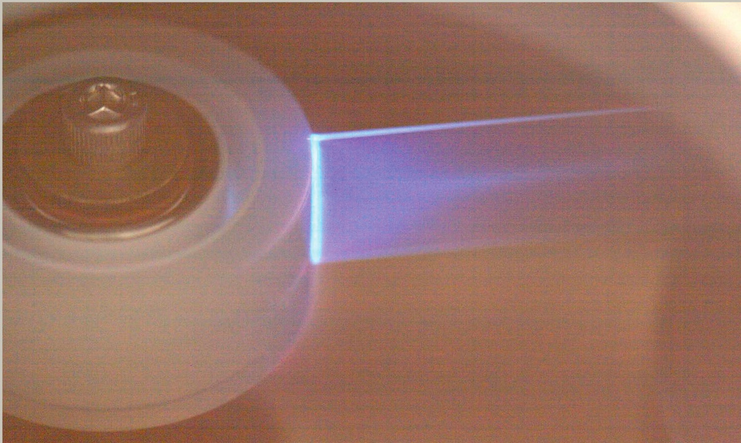 Figure 1. Triboluminescence from peeling tape. Figure courtesy of C. Camara, Juan V. Escobar and S. Putterman.
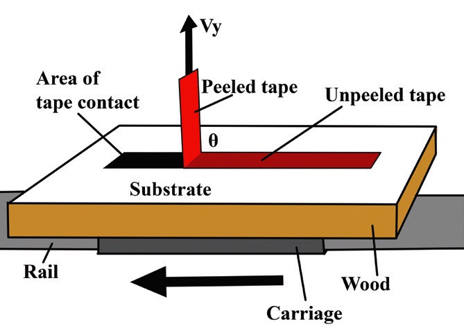
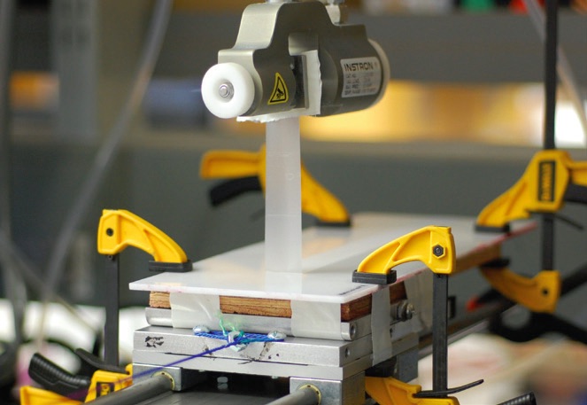
Figure 2. (a) Schematic of peeling procedure. Scotch® tape is applied to a substrate and peeled at angle θ (θ =90° shown). The substrate is clamped to a wood chassis, which in turn is attached to a sliding carriage that maintains a constant θ. (b) Peeling at regulated rate by a Single Column Materials Testing System (Instron® Model 5800), showing linear bearings that ride on fixed rails, allowing the carriage to move smoothly as the clamp at the top of the panel moves vertically upward.
Toner application
Two Powder Spray Gun (PSG) jars were separately filled with Xerox Black 6R881 and Samsung Magenta CLP-M300A toner, respectively. The spray jars were fed a stream of air from dedicated air compressors to force powder out of an adjustable nozzle. These powder paint systems are typically used for art projects, e.g. powder painting metal fishing lures, but they distribute toner by the same mechanism. By using two PSGs, we simultaneously produced uniform mists of the two colored toners. We added metal ball bearings to the jars, which charged the black toner positively and the magenta toner negatively. We remark that this differs from bipolar toner used to identify surface charges in other work
24,25 in which the two toners are mixed together; we chose to charge and deploy the toners separately in the expectation that this would more strongly and reproducibly charge particles than has been done previously. By Coulomb’s law, the black (magenta) toner thereby colored negatively (positively) charged regions as shown in Figures 3-5. A custom Toner Containment Unit (TCU) about 110 x 53 x 53 cm in size was designed with an XOA range hood and MERV 11 filters for filtration of toner particles. The twin fans in the hood produced air circulation within the TCU, which effectively removed excess toner from surfaces being sprayed, while the filters removed toner from exhaust air. A thick plastic sheet was affixed to the front of the TCU as a variable-height sash. Immediately after peeling using the Instron tensile testing system, the substrate and tape were placed into the TCU, and the end of the tape was clipped such that both the area of contact and the tape’s surface could be sprayed with the toner. The toner was applied for approximately 10 seconds with the PSGs while the TCU’s fans were active. After 10 seconds, we allowed the excess toner to be filtered through the fans until all visible airborne particles have been removed.
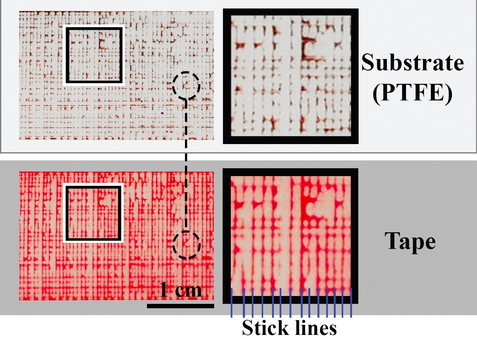 Figure 3. Tape (bottom) peeled from a PTFE substrate (top) and exposed to bipolar toner as described in text. Tape and substrate are horizontally registered in this figure, so that features such as the area in the dotted circles are aligned. Notice that stick-slip events appear as vertical lines, where the black (magenta) toner identifies negatively (positively) charged regions. Color variations arise due to lighting and related imaging details. Additional image processing details are described in the Appendix.
Figure 4. Tape (bottom) peeled from PTFE substrate (top) and exposed to bipolar toner as described in text; photographs are horizontally aligned (see dotted circles for corresponding features). Stick-slip events appear as vertical lines and with the same charge identification as in Figure 3. Notice the increased spatial frequency of the stick events compared to Figure 3 as indicated by the vertical blue lines. Color variations arise due to lighting and related imaging details.
Figure 5. Tape (bottom) peeled from PMMA substrate (top) and exposed to bipolar toner as described in the text and horizontally aligned. The black (magenta) toner has identified the negatively (positively) charged regions; here, charges are seen opposite those of Figures 3 and 4. Stick-slip events appear at an even higher spatial frequency than in the two PTFE samples of Figures 3 and 4. Color variations between the previous figures and Figure 5 arise due to lighting and related imaging details.
Data collection
The substrate area beneath the area where the tape was adhered was cleaned with isopropyl alcohol and Kimwipes and dried. The suspended tape was then carefully removed and placed on the substrate below where it was peeled such that the tape is adjacent to its corresponding substrate area. Photographs were taken using a Nikon D40 camera with AF Micro Nikkor 60 mm lens. Images were cropped and horizontally aligned in Adobe Photoshop 2020. For Figures 3-5, four adjustment masks were applied uniformly to reduce differences due light sources and improve print visibility: Yellow Saturation -100, Yellow Lightness +100, Brightness +50 and Contrast +20. Data analysis was performed on the unmasked photographs.
Data analysis
We performed image processing on the cropped, unmasked photos to evaluate the spatial frequency of the stick-slip lines produced by toner exposure, as shown in Figure 6(a). For each trial, the mean distance between stick events was calculated through the length of the tape (about 14 cm). Values two standard deviations from the trial’s mean were considered outliers and removed. Plot in Figure 6(b) show means ± standard error.
 Figure 6. (a) Grayscale and threshold processing of stick-slip image from Figure 3. Black pixels carry a value of 0 and white pixels carry a value of 1. The bottom plot is the sum of these numerical values over each column of pixels, and minima (black lines) are identified by red asterisks. (b) Plot of the mean distance between sticks from 13 individual trials using three materials using the analysis shown in panel (a). Error bars represent ± standard error of the mean after outliers have been discarded (see text).
REFERENCES
1.
Lacks, D.J. (2012), The unpredictability of electrostatic charging.
Angew Chem Int Ed.,
51 (28): pp. 6822-6823. doi: click
here.
2.
Lacks, D.J. and Shinbrot, T. (2019), Longstanding and unresolved issues in triboelectric charging.
Nature Reviews Chemistry,
3 (8): pp. 465-476. Click
here. Accessed March 1, 2021. doi: 10.1038/s41570-019-0115-1.
3.
Camara, C.G., Escobar, J.V., Hird, J.R. and Putterman, S.J. (2008), Correlation between nanosecond X-ray flashes and stick–slip friction in peeling tape.
Nature,
455 (7216): pp. 1089-1092. Accessed June 12, 2019. doi:10.1038/nature07378.
4.
Hird, J.R., Camara, C.G. and Putterman, S.J. (2011), A triboelectric x-ray source.
Appl Phys Lett.,
98 (13): p. 133501. Click
here. Accessed March 1, 2021. doi:10.1063/1.3570688.
5.
Houser, J.G., Farrell, W.M. and Metzger, S.M. (2003), ULF and ELF magnetic activity from a terrestrial dust devil.
Geophys Res Lett.,
30 (1). doi: click
here.
6.
Delory, G.T., Farrell, W.M., Atreya, S.K., et al. (2006), Oxidant enhancement in martian dust devils and storms: Storm electric fields and electron dissociative attachment.
Astrobiology,
6 (3): pp. 451-462. Accessed March 30, 2021. doi: 10.1089/ast.2006.6.451.
7.
Pingali, K.C., Hammond, S.V., Muzzio, F.J. and Shinbrot, T. (2009), Use of a static eliminator to improve powder flow.
International Journal of Pharmaceutics,
369 (1): pp. 2-4. Click
here. Accessed March 1, 2021. doi: 10.1016/j.ijpharm.2008.12.041.
8.
Glor, M. (1985), Hazards due to electrostatic charging of powders.
Journal of electrostatics,
16 (2): pp. 175-191. Click
here.
9.
Paasi, J. (2005), Assessment of ESD threats to electronic components.
Journal of electrostatics,
63 (6): pp. 589-596. Click
here. doi: 10.1016/j.elstat.2005.03.021.
10.
Diaz, A.F. and Felix-Navarro, R.M. (2004), A semi-quantitative tribo-electric series for polymeric materials: The influence of chemical structure and properties.
Journal of Electrostatics,
62 (4): pp. 277-290. Click
here. Accessed March 25, 2021. doi: 10.1016/j.elstat.2004.05.005.
11.
Henniker, J. (1962), Triboelectricity in polymers.
Nature,
196: p. 474. Click
here.
12.
Kaproth, B.M. and Marone, C. (2013), Slow earthquakes, preseismic velocity changes, and the origin of slow frictional stick-slip.
Science,
341 (6151): p. 1229. Click
here. doi: 10.1126/science.1239577.
13.
Shinbrot, T., Kim, N.H. and Thyagu, N.N. (2012), Electrostatic precursors to granular slip events.
Proceedings of the National Academy of Sciences - PNAS, 109 (27): pp. 10806-10810. Click
here.
14.
Shinbrot, T., Alexander, A. and Muzzio, F.J. (1999), Spontaneous chaotic granular mixing.
Nature.
397 (6721): pp. 675-678. Click
here. Accessed March 26, 2021. doi: 10.1038/17760.
15.
Ciccotti, M., Giorgini, B. and Barquins, M. (1998), Stick-slip in the peeling of an adhesive tape: Evolution of theoretical model.
International Journal of Adhesion and Adhesives,
18 (1): pp. 35-40. Click
here. doi: 10.1016/S0143-7496(97)00067-5.
16.
Gandur, M.C., Kleinke, M.U. and Galembeck, F. (1997), Complex dynamic behavior in adhesive tape peeling.
Journal of Adhesion Science and Technology,
11 (1): pp. 11-28. Click
here. Accessed June 12, 2019. doi: 10.1163/156856197X00994.
17.
Dalbe, M., Cortet, P., Ciccotti, M., Vanel, L. and Santucci, S. (2015), Multiscale stick-slip dynamics of adhesive tape peeling.
Phys Rev Lett.,
115 (12): pp. 128301. Accessed June 12, 2019. doi: 10.1103/PhysRevLett.115.128301.
18.
Thoroddsen, S.T., Nguyen, H.D., Takehara, K. and Etoh, T.G. (2010), Stick-slip substructure in rapid tape peeling.
Physical review. E, Statistical, nonlinear, and soft matter physic,
82 (4 Pt 2): p. 046107. Click
here. doi: 10.1103/PhysRevE.82.046107.
19.
Horvat, J. and Lewis, R.A. (2009), Peeling adhesive tape emits electromagnetic radiation at terahertz frequencies.
Opt Lett, OL,
34 (14): pp. 2195-2197. Click
here. Accessed June 12, 2019. doi: 10.1364/OL.34.002195.
20.
Luo, N., Feng, Y., Zhang, L., et al. (2021), Controlling the tribological behavior at the friction interface by regulating the tribo-electrification.
Nano Energy,
87: p. 106183. Click
here. Accessed June 10, 2021. doi: 10.1016/j.nanoen.2021.106183.
21.
Picard, J. (1676), Experience faite a L’observatoire fur le barometre (imple touchant un nouveau phenomene qu’on y a decouvert).
Le Journal des sçavans, pp. 112-113. Click
here.
22.
Harvey, E.N. (1939), The luminescence of adhesive tape.
Science,
89 (2316): pp. 460-461. Click
here. Accessed June 12, 2019.
23.
Donald D.K. (1968), Contact electrification of insulators and its relevance to electrets.
J Electrochem Soc.,
115 (3): p. 270. Click
here. Accessed June 7, 2021. doi: 10.1149/1.2411128.
24.
Shinbrot, T., Komatsu, T.S. and Zhao, Q. (2008), Spontaneous tribocharging of similar materials.
EPL (Europhysics Letters),
83 (2): p. 24004. Click
here. doi: 10.1209/0295-5075/83/24004.
25.
Shinbrot, T., Jones, B. and Saba, P. (2018), Charging at a distance.
Phys Rev Materials,
2 (11): p. 115603. Click
here. doi: 10.1103/PhysRevMaterials.2.115603.
26.
An, S., Sankaran, A. and Yarin, A.L. (2018), Natural biopolymer-based triboelectric nanogenerators via fast, facile, scalable solution blowing.
ACS Appl Mater Interfaces,
10 (43): pp. 37749-37759. Click
here. doi: 10.1021/acsami.8b15597.
27.
Khandelwal, G., Maria Joseph Raj, Nirmal Prashanth and Kim, S. (2020), Triboelectric nanogenerator for healthcare and biomedical applications.
Nano Today,
33: p. 100882. Click
here. doi: https://doi.org/10.1016/j.nantod.2020.100882.
28.
Yao, C., Hernandez, A., Yu, Y., Cai, Z. and Wang, X. (2016), Triboelectric nanogenerators and power-boards from cellulose nanofibrils and recycled materials.
Nano Energy,
30: pp. 103-108. Click
here. Accessed April 28, 2021. doi: 10.1016/j.nanoen.2016.09.036.
29.
Pu, X., An, S., Tang, Q., Guo, H. and Hu, C. (2021), Wearable triboelectric sensors for biomedical monitoring and human-machine interface.
iScience,
24 (1): p. 102027. Click
here. doi: https://doi.org/10.1016/j.isci.2020.102027.
30.
Sugizaki, Y. and Suzuki, A. (2005), Unsteady peeling accompanied by oscillations of adhesive tape from a soft adherend.
Soft matter,
15 (35): pp. 7080-7088. Click
here.
31.
Lowell, J. and Akande, A.R. (1988), Contact electrification-why is it variable?
J Phys D: Appl Phys.,
21 (1): pp. 125-137. Click
here. Accessed May 7, 2021. doi: 10.1088/0022-3727/21/1/018.
32.
Castellani, L., Castiglioni, A., Ferri, D., Baraldi, A., Martinelli, L. and Rotunno, S. (2015), Rate effects on adhesion energy between polyethylene films and different substrates.
Engineering fracture mechanics,
149: pp. 387-401. Click
here. doi: 10.1016/j.engfracmech.2015.07.015.