KEY CONCEPTS
•
Cavitation is a physical phenomenon that can result in serious damage to hydraulic systems through the generation and collapse of gas bubbles.
•
A theory has now been developed to predict operating conditions when cavitation will occur and the size of the cavitation bubble.
•
Experimental data was used to validate the theory through the use of a phase diagram using two cavitation numbers known as Ca
1 and Ca
2.
Cavitation is a physical phenomenon that can result in serious damage to hydraulic systems such as pumps, pipelines and water turbines. During cavitation events, air bubbles present in the fluid can collapse leading to the generation of shock waves, violent jets and overloads, which can cause damages, from local wear to system failure, to hydraulic machinery.
Zhao Pan, professor of mechanical and mechatronics engineering at the University of Waterloo in Waterloo, Ontario, Canada, says, “When the local pressure in a fluid is dropped below the vapor pressure of the liquid in a short time, the liquid is ‘evaporated’ immediately—and gas bubbles form. The bubbles won’t last long and will eventually collapse, leading to unfavorable situations, such as noises and damages.”
Pan continues, “As the bubble collapses, the ambient fluid keeps accelerating until it hits. This results in an implosion and produces damaging water hammer effect, high-speed jets and shock waves that cannot just destroy structures of a pump, hydraulic turbine and pipeline but also cause serious damage to materials such as metal alloys and ceramics used in hydraulic systems. Cavitation is a classic topic in fluid mechanics, and the phenomena have been found in many engineering applications.”
In specific applications, such as pipelines and hydraulic turbines, cavitation commonly takes place near valves and/or elbows of these structures. Figure 2 shows an example of cavitation, which is triggered by hitting a fluid containing glass bottle against a surface. The pressure at the bottom of the bottle drops significantly, producing cavitation bubbles that implode with sufficient power to break the glass. The suddenly accelerated bottle bottom induced by the hitting simulates a valve closing too fast.
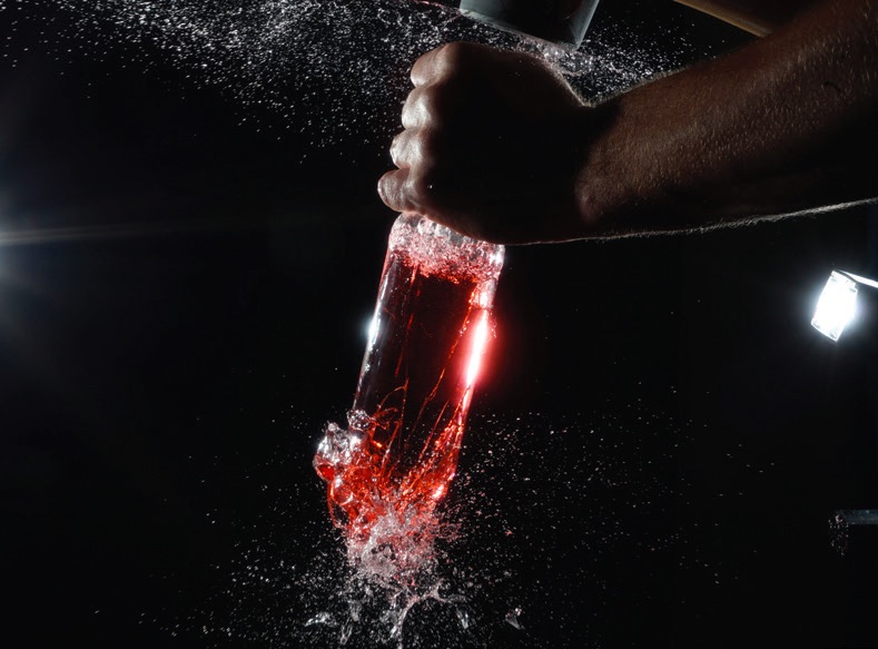 Figure 2. Cavitation can be triggered by hitting a fluid containing glass bottle against a surface, as shown in this figure. Figure courtesy of Tadd Truscott, Splash Lab, Utah State University.
One should note that cavitation takes place without the presence of outside gas. In contrast, aeration of a hydraulic system occurs when outside air enters the suction inlet of the pump. Entrained air is the major source of foam problems in aqueous and non-aqueous lubricants. A recent TLT article
1 discusses the single bubble/drop test, which can be used to evaluate interactions between individual bubbles and the dynamics of thin liquid films between bubbles.
Past studies evaluating cavitation have provided further insight into how bubbles form and then collapse. Work done to understand cavitation in pipelines has looked at pressure variations and validated relevant numerical simulations.
A need exists for developing a method to predict operating conditions when cavitation will occur and to determine when large and destructive bubbles, as opposed to small bubbles, will form. Such an approach has now been established through experimentation and theoretical modeling.
Modified tube-arrest test
The researchers conducted a series of experiments in a liquid-filled test tube using the modified tube-arrest approach. Pan says, “This test involved filling an acrylic tube with degassed water to heights of 200-700 millimeters. A lever that acts as an actuator drives the tube in an upward motion until the top hits a stopper. In this way, the sudden deceleration of the liquid generates cavitation bubbles at the bottom of the tube. Our modification can decouple the acceleration and velocity of the moving fluid.”
The modified tube-arrest apparatus is a low-cost and safe laboratory experimental setup to study cavitation dynamics in tubular structures. The acceleration of moving fluid is associated with how fast one shuts off a valve or a turbine, and the velocity represents how fast the liquid initially is moving in the hydraulic pipeline.
Predicting bubble formation was made through the use of the nondimensional cavitation number, which is a measure of the relationship between the overpressure in the liquid flow to the pressure drop. Pan says, “We developed a theory with two cavitation numbers, which are known as Ca
1 and Ca
2, to predict if cavitation can occur and the size of the cavitation bubble during the transient process. Ca
1 is related to the fluid’s acceleration, and if this value is less than unity, then cavitation is almost inevitable, while if this value is greater than one, cavitation is not likely to happen. The acceleration is controlled in our experiments through adjusting the movement of the actuator and the cushion materials attached to the stopper.”
The second cavitation number, Ca
2, is used by the researchers to predict the size of the cavitation bubble. Pan says, “Ca
2 is related to the slenderness of the liquid column and its speed in a tubular structure. A Ca
2 value less than one predicts the formation of a large bubble, and liquid separation is likely to happen. Such a big bubble may cause structural failures beyond local wear and tear, which are usually caused by small cavitation bubbles.”
The researchers used experimental data to validate their theory on a phase diagram with Ca
1 on the y-axis and Ca
2 on the x-axis. No cavitation is seen in the region where Ca
1 is greater than one while the diagram splits between large and small bubbles with Ca
1 values below one and Ca
2 values either above or below one, respectively.
The study also concluded that the finite collapse velocity of a spherical cavitation bubble is equivalent to the initial flow velocity. “When cavitation happens in a long and fast-moving liquid column, the cavitation bubble can be large, and the violent implosion can easily burst pipes. This failure happened in our preliminary tests. Fortunately, our modified tube-arrest setup is safe. No one was hurt; we just have to build a new and stronger tube,” says Pan.
Figure 3 shows the process from the onset of cavitation until the collapse of the bubble.
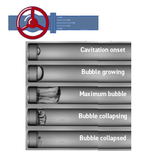 Figure 3. The cavitation process, starting in the top image with the formation of a bubble, progresses through the bubble growing and then, in the bottom image, collapsing. Figure courtesy of Peng Xu, Tsinghua University, and Zhao Pan, University of Waterloo.
Pan is interested in using this finding to help evaluate hydraulic systems to predict and mitigate damages and noises caused by cavitation. He says, “We would like to assist users of hydraulic systems in troubleshooting the unpleasant outcomes from cavitation and reduce the risks of cavitation.”
Additional information on this research can be found in a recent article
2 or by contacting Pan at
zhao.pan@uwaterloo.ca.
REFERENCES
1.
Canter, N. (2021), “Single bubble/drop test to evaluate foaming and emulsion,” TLT,
77 (2), pp. 16-17.
2.
Xu, P., Liu, S., Zuo, Z. and Pan, Z. (2021), “On the criteria of large cavitation bubbles in a tube during a transient process,”
Journal of Fluid Mechanics, 913, R6, DOI:
https://doi.org/10.1017/jfm.2021.114 .