Wet friction materials
Jeanna Van Rensselar, Senior Feature Writer | TLT Lubrication Fundamentals August 2020
Trends in development include creating materials with larger torque capacity, higher thermal stability and heat dissipation, better wear resistance and durability and lower cost.
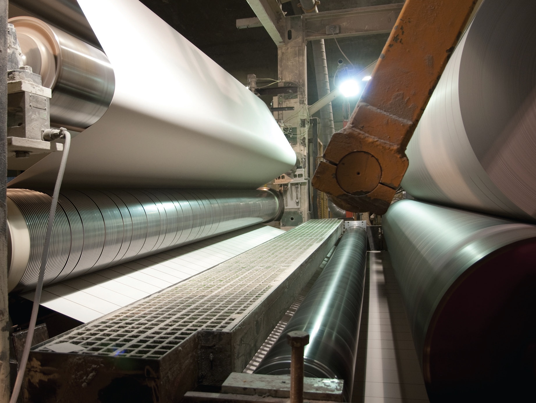
The most common type of wet friction material is wet-lay organic friction material, also known as a paper material since it is produced on a paper-making machine.
KEY CONCEPTS
• The tribology of wet friction materials involves many disciplines, including material science, mechanics, physics and chemistry.
• Constituents of wet friction materials include fibers, fillers and resins.
• For high energy and continuous slip applications, wet is preferred over dry since the frictional heat is removed more effectively with oil than air.
Friction materials that operate in fluid media are called wet friction materials (WFMs). WFM is a compressible, porous and permeable material that operates in oil and transfers torque to and from metal plates that are in contact with the wet friction plates. When a wet clutch engages, kinetic energy is converted into frictional heat that must be tolerated by the WFM and absorbed primarily by the metal and oil.
There are several types of WFMs. According to STLE-member Dr. Bulent Chavdar, STLE Detroit Section chair and senior engineering specialist, Materials and Power Transfer Systems CoE, Eaton Corp., the most common type is wet-lay organic friction material, also known as a paper material since it is produced on a paper-making machine.
The less common types are air-lay, woven, pultruded, sintered and thermal spray materials. WFMs also can be classified by applications such as holding, engaging or slipping, as well as high energy versus low energy, high pressure versus low pressure.
Chavdar explains that the major requirements of WFMs are smooth engagement or noise resistance, long-term durability or reliability, thermal and pressure resistance, oil compatibility, glaze resistance, high torque and consistent torque in a wide range of operating conditions that include speed, pressure, temperature and environment.
The tribology of WFM involves many disciplines including material science, mechanics, physics and chemistry. It is concerned with the sliding contact and tribology of boundary and hydrodynamic regimes of lubrication.
WFM immersed in a lubricating fluid provides smoother clutch performance and has better cooling of the friction contact than dry friction clutches. STLE-member Dr. Vladimir Klotchikhine, senior test engineer with Greening Testing Laboratories, Inc., gives this example: If the dry clutch’s typical coefficient of friction is within 0.25-0.35, then in wet clutches the typical coefficient of friction is within 0.07-0.15.
Wet and dry friction materials difference
WFMs are intentionally made porous (30%-70%), made thin (0.3-1.3 mm) and designed for life. “Wear is negligible since the direct contact of asperities is reduced significantly or eliminated due to the presence of an easy-to-shear oil film at the interface as observed by in situ friction interface visualization techniques,” Chavdar explains. “WFMs are bonded on a steel core plate by adhesive. Dry friction materials (DFMs) are low-porous, although some porosity might not be avoidable in certain manufacturing processes. DFMs are thick, typically 3-15 mm since they wear and therefore have limited life. DFMs are attached on backing plates by bonding, fastening, brazing, welding or a hybrid of these techniques. They must be replaced at regular intervals in brake or clutch applications.”
In wet brakes, oil affects the friction properties and acts as a coolant. The coefficient of friction in wet brakes is typically between 0.1 and 0.2, although there are certain operating conditions where lower and higher coefficients than those can be observed. The coefficient of friction in dry brakes is typically between 0.3 and 0.6.
“For high energy and continuous slip applications, wet is preferred over dry since the frictional heat is removed more effectively with oil than with air,” Chavdar says. “Low lining thickness enables the packing of multiple plates in a wet brake, thereby transferring higher torques. Wet brakes also provide smoother engagement than dry brakes. Dry brakes are preferred when simplicity of design and lower initial cost are the main concerns.”
Fundamental lubrication mechanisms
There are two contributors to the total frictional torque that act simultaneously: asperity torque and hydrodynamic torque. “The new concept of simultaneous load sharing among the lubrication regimes is different than the sequential transitions from boundary to elastohydrodynamic to hydrodynamic regimes, as described by the older Striebeck curves and more applicable for WFMs,” Chavdar says. “The theory of load sharing highlights the importance of permeability, elastic modulus and surface texture of WFMs, as well as oil viscosity on the fluid film thickness, coefficient of friction and the torque curve shape during an engagement.”

In the case of vehicles, the transmission fluid transfers torque and power from the vehicle’s engine to the powertrain and drivetrain mechanisms through various wet clutch systems.
He continues, “However, the boundary behavior of WFM as the dominating regime at low speeds still needs to be determined experimentally with the help of theoretical guidance on the physical properties.”
The constituents of wet-lay WFMs can be classified three ways:
1. Fibers include aramid, cellulose, carbon, mineral and glass types.
2. Fillers include metallic, ceramic and organic particles such as diatoms, carbon, graphite, rubber, oxides, silicates, carbonates, sulfates, carbides, nitrides and solid lubricants.
3. Resins include phenolics and modified phenolics, epoxy, silicone, melamine and polyimide. These can be standalone or mixed with phenolics in WFMs.
WFMs can be developed with the oil of a specific application in mind and need little or no help from additional additives post-development.
Transmission fluids affect WFM performance
In the case of vehicles, the transmission fluid transfers torque and power from the vehicle’s engine to the powertrain and drivetrain mechanisms through various wet clutch systems.
“The clutch itself is a mechanical device that is used to transmit mechanical power, usually through the kinetic motion, from a driving member to a driven member of a mechanical system,” Klotchikhine explains. “This is due to the connection or engagement of their elements for either a short or long time. Thus, the clutch provides an interruptible connection between two rotating shafts.”
Friction clutches gradually engage. The driving shaft might be rotating at full speed while the driven shaft is either stationary or rotating at a much lower speed. The torque-transmitting efficiency of friction clutches depends on the frictional force between WFMs and the mate or counterface surface, which are pressed together.
The mate material is usually made of a hard-solid metal: as a rule, a steel alloy. In situations where the transmission fluid interacts with these two bodies under various contact pressures and elevated temperatures, the soft material performance of WFM and its properties become important.
Klotchikhine explains that friction clutches can have either two plane disks or multiple plane disks. The latter have several friction surfaces and are usually used to multiply the transmitting torque and reduce the unit load on the friction material surface. Friction clutches permit smooth engagement at any speed. In the event of overloads, the friction clutch slips momentarily, safeguarding the machine or mechanism against breakage.
Based on the shape of the friction linings, friction clutches are classified as disk clutches, cone clutches or centrifugal clutches. Disk clutches account for most of the friction clutches in modern vehicle drivetrain and driveline clutch mechanisms.
In wet clutch systems (WCS), transmission fluid helps to transfer power on a long-term basis. In the automotive industry, where wet clutches are utilized widely, they operate mostly with transmission fluid that can have many modifications depending on the type of transmission.
• In automatic transmissions, it is called automatic transmission fluid (ATF).
• In dual clutch transmissions, it is called DCT fluid (DCTF).
• In continuously variable transmissions, it is called CVT fluid (CVTF).
• In manual transmissions, it is called MT fluid (MTF).
Torque converter clutches, shifting clutches, transfer case clutches and limited slip differential clutches all utilize transmission fluids.
“Transmission fluid is a hydraulic and lubricating oil and can, by its chemistry, be a semisynthetic and fully synthetic multifunctional fluid,” Klotchikhine says. “Primarily they are made of a refined petroleum. They are low-viscosity fluids. Base oil content in ATF is usually around 88%-90%, and additive volume is around 10%-12%. ATF mostly uses Group II base oil—hydrotreated mineral oils and Group III—hydrocracked mineral oils.”
The ATF should have steady viscosity behavior over a wider temperature range and excellent temperature stability under high stress loads. A typical ATF additive package has friction modifiers, oxidation and corrosion inhibitors, antiwear and antifoam agents, dispersants, seal swell protectors and viscosity index modifiers.
“Transmission fluid should increase the stability of friction contact and support the required coefficient of friction during clutch engagements,” Klotchikhine explains. The fluids also should provide and perform the following functional tasks:
• Smooth gear shifting
• Mitigate shudder phenomena
• Absorb heat formed during friction contact
• Transfer wear particles out of the friction contact area
• Protect counterface materials from wear and prevent “hot spots” from forming
• Cool the friction interface
• Lubricate contacting surfaces
• Prevent steel corrosion
• Operate well with wet friction material, permeability capacity and porosity design
• Protect against its own mechanical, thermal and chemical degradation (i.e., be durable and functionally efficient in operation).
Transmission fluid can have a negative effect on the WFM’s tribological and functional performance, specifically glazing and system shudder.
Glazing is a thin, smooth film that forms on the external surface of the friction material. It is strong and looks like a coating. It is a kinetic process and very much depends on the functional stability of various additives that are added to the base oil to perform special functions during repeated sliding boundary friction contact between a WFM and counterface surface texture. The resulting WCS instability during the glazing formation leads to system shudder (see Figure 1).
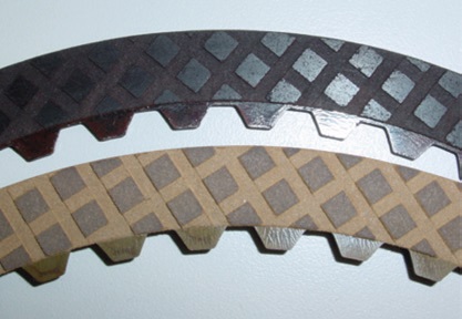
Figure 1. Overview of glazed and original surfaces: The upper friction plate has glazing, and the lower plate presents the original friction material before the test. Figure courtesy of Dr. Vladimir Klotchikhine.
“The clutch running with partial slip in contact causes the mechanical system’s inherent vibration (see Figure 2),” Klotchikhine says. “The amplitude of such vibrating depends on the clutch operating conditions, wet friction material resiliency and other mechanical and thermal properties and material design configuration (i.e., groove design if they are on the material surface). When such fluctuations become harsh, they are accompanied by a loud sound indicating the wet clutch system has a shudder.”
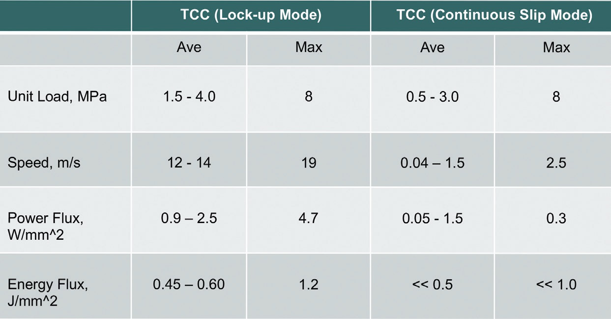
Figure 2. Typical wet friction material operation parameters for TCC operating under lock-up and continuous slip modes. Figure courtesy of Dr. Vladimir Klotchikhine.
WFM development and evaluation
WFM requirements and their priorities are different for each application. Chavdar explains, “For example, engaging clutches require smooth engagement or lower static coefficient of friction than dynamic coefficient of friction. On the other hand, holding clutches require high static coefficient of friction without any regard to the level of dynamic coefficient of friction. Another criterion for a smooth engagement is a positive coefficient of friction versus speed slope. Permeability, elastic modulus and roughness of WFMs play important roles in achieving desirable torque shapes (see Figure 3).”
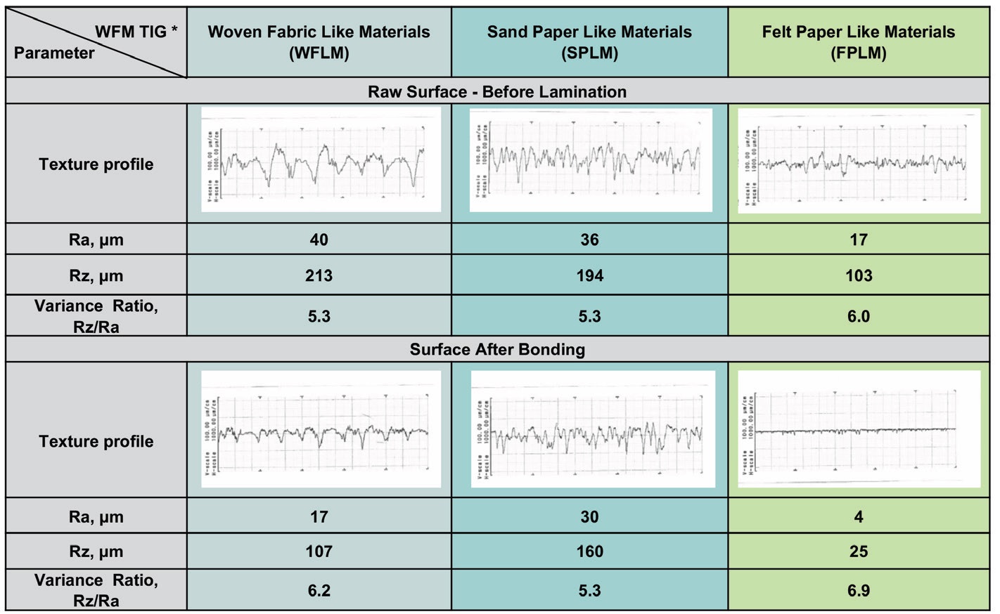
Figure 3. Texture and roughness parameters of wet friction materials under the TIG classification. Figure courtesy of Dr. Vladimir Klotchikhine.
Chavadar adds that WFMs need to be tested for mechanical, thermal and transport properties on standalone test samples and for friction and durability characteristics as part of a clutch/brake sub-system, or in a machine system, such as in a differential or a full vehicle.
Typically, the qualification tests progress from abstract tests such as bench-type tests to full system tests as the technology readiness level increases throughout the project. Mechanical, thermal and transport properties need to be tested in the direction of use.
Chavdar explains, “For example, the elastic modulus in compression is more relevant than the moduli in tension or shear for WFM applications. Likewise, the fatigue life of WFM needs to be tested in compression. Permeability depends on the direction of measurement as well. It is best to measure the permeability, both in normal and radial directions.”
There are several special test machines that are utilized for testing wet friction materials—CST or continuous slip tester, various types of vertical loading types, friction test machines such as low- or medium-velocity friction apparatuses (VFT, LVFA, MVFA) and horizontal loading types as synchronizer test rigs and inertia dyno test machine such as SAE No. 2 and GK-type test benches.
WFM design criteria
Klotchikhine explains that contact surface area resistance to high load, speed and temperature operating conditions depends on the materials’ mechanical and thermal deformation, the gap between WFM and counterface materials and ATF properties, and the WFM surface design can be either flat or have grooves on the friction contact area to manipulate the friction coefficient and the cooling and lubrication of the friction material itself.
For low WFM wear, the pressure distribution between the material surface and the mate surface should be close to uniform along the radial direction of the friction contact surface. When the friction material contact surface is overloaded, it forms local overheated spots (hot spots) on the mate surface that, in turn, can provoke a buildup of glaze on the friction material surface.
WFM durability also depends on a substrate surface design geometry and flexibility as well as the applied material stiffness. The substrate surface is usually designed as a disc plate where the friction material is connected or bonded under a special technological process. If the substrate material is not strong enough, the pressure distribution onto the friction contact area is not steady. It provokes serious load displacements that can lead to the thin wet friction material overloading.
Friction materials should resist sliding wear and thermal compression stress fatigue. Well-made wet friction materials are able to provide better clutch operating comfort. They have longer slipping engagement life, are more durable and absorb higher total friction energy along with higher power losses.
According to Klotchikhine, the design criteria to tailor WFM formulation for typical applications should address the following operational demands and requirements. WFMs should:
• Possess high energy of friction absorption (for smoothing the engagement process and making the shifting procedure more comfortable for a driver)
• Provide high and stable friction coefficient during engagements (for clutch efficient torque capacity)
• Have high wear resistance (for efficient and durable clutch performance)
• Produce low noise during engagements (for driver comfort)
• Help create the clutch positive friction gradient, with speed that should be kept as long as possible (to mitigate shudder in the clutch)
• Have the ability to withstand high temperatures (for clutch efficient cooling capacity)
• Have durability and stability (to withstand high operating loads and temperatures during long-term clutch operation)
• Possess excellent compatibility with counterface material texture and operation fluid (to prevent mate wear and prevent fast transmission fluid degradation).
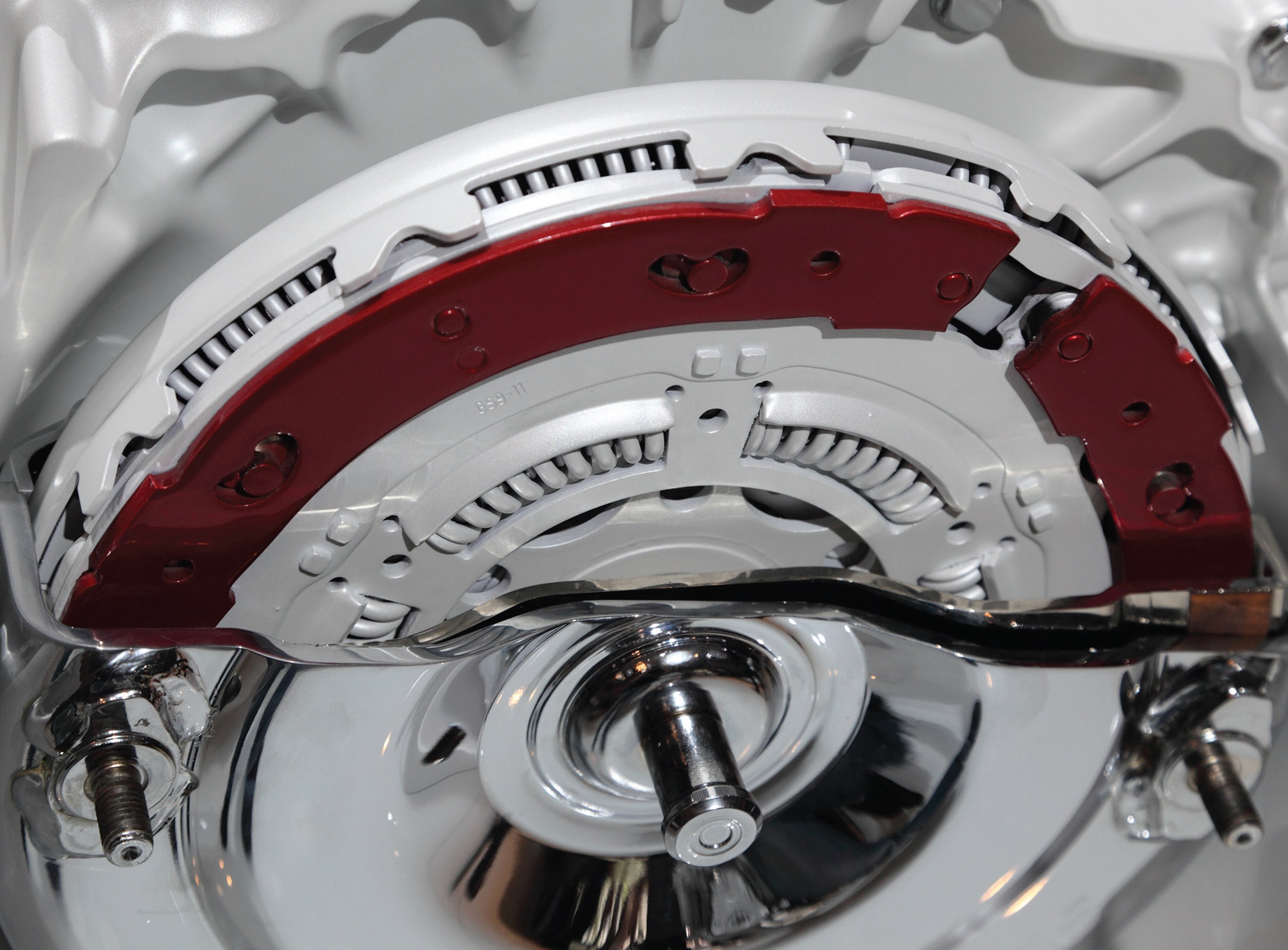
Fly wheel and clutch of a modern motor.
Expanding the operating range of WFM
Chavdar says the operating range of friction materials can be expanded by several strategies that might be employed individually or simultaneously; these include new ingredients, new formulations, new manufacturing and post-processing techniques and new oil groove and design features.
“High-temperature applications can be addressed by wet-lay materials with high heat-resistant fibers, fillers and resins, as well as by improved clutch geometries, oil groove, segmenting and oil circulation designs,” Chavdar says. “High-pressure applications can be addressed by high modulus wet-lay materials containing high modulus fibers, fillers and resin. Even higher-temperature and higher-pressure applications can be addressed by alternative manufacturing methods such as sintered and thermal spray materials in combination with new oil distribution, heat mitigation and design strategies (see Figure 4).”
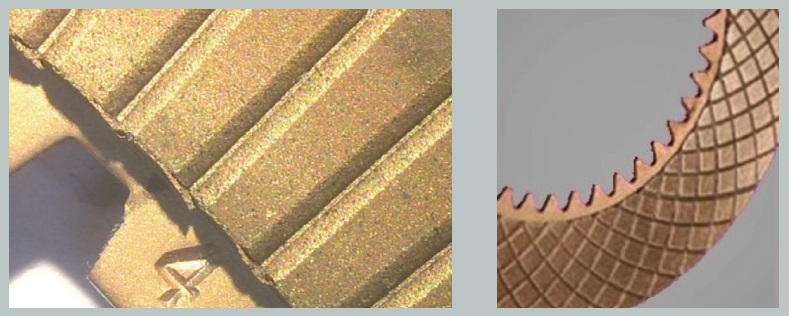
Figure 4. Sintered friction material with different groove designs. Figure courtesy of Dr. Vladimir Klotchikhine.
Another strategy for expanding the operating range of WFMs should be developing materials having more compatibility with ATF. Klotchikhine says, “Such symbiosis will help absorb noise and vibration at a wide range of clutch speeds and higher loading conditions. The fluid characteristics will continue to be modified in this direction because such interconnection influences clutch dragging losses.”
Klotchikhine adds that cleanliness, frictional properties, oil compatibility, shear stability, antifoaming properties and high-temperature stability of the WFMs are all critical for maintaining good clutch operation. The materials’ mechanical properties should resist thermal and load compression overloading, stress fatigue, material peeling off and wear during sliding friction.
Finally, the mate surface material, texture, roughness, surface treatment, hardness, geometrical requirements and surface dimensional defects such as runout, flatness and waviness, gap variance, piston plate design and its stiffness and flexibility should get more attention since they impact WFM functional performance significantly. The mate surface design and technological particularities and displacements have a strong impact on the plate’s hot spots and dishing forming.
Klotchikhine concludes, “The variety of wet friction materials will grow as they include the whole spectrum of WFMs on the market—from the original WFM to sinter and special coatings. We can assume that the major trends in WFM development will involve developing materials that have larger torque capacity, higher thermal stability and heat dissipation, wear resistance and durability and lower cost.”
Jeanna Van Rensselar heads her own communication/public relations firm, Smart PR Communications, in Naperville, Ill. You can reach her at jeanna@smartprcommunications.com.