Visualisation of structured lubricants in tribological contacts
Robert J. Elkington and Dr. Monica Ratoi | TLT Scholarship Research June 2020
National Centre for Advanced Tribology at Southampton (nCATS) at the University of Southampton, UK
Online only in TLT Archives
Booser Scholarship Paper
The E. Richard Booser Scholarship Award is awarded annually to undergraduate students who have an interest in pursuing a career in tribology. As a requirement for receiving an STLE scholarship, students participate in a tribology research project and submit a report summarizing their research. For more information about the Booser scholarship, visit www.stle.org.
The 2019 recipient of The E. Richard Booser Scholarship Award is Robert Elkington, a mechanical engineering graduate from the University of Southampton. During his studies, he completed an internship and bachelor's dissertation at the National Centre of Advanced Tribology at Southampton (nCATS), University of Southampton, investigating biologically inspired structured lubricants. He finished top of the year with a 1st class bachelor’s degree in mechanical engineering from the University of Southampton in 2019. In the fall, Elkington will begin a doctorate in biotribology at the University of Leeds.
Elkington conducted his scholarship research under the supervision of Dr. Monica Ratoi, investigating the use of polarized light microscopy techniques for understanding liquid crystal behavior in high-pressure, high-shear EHD contacts. Complementary to his studies, he is a keen climber and alpinist and has been active in the Southampton University Mountaineering Club for four years. You can reach him at R.J.Elkington@protonmail.com.

Robert Elkington
Abstract
The layered, lamellar phase of lyotropic liquid crystals display promising tribological properties possessing low shear strength between layers, solid like elasticity and high load carrying capacity perpendicular to their layered structure. Being able to visualise and study the behaviour of LLC in high pressure contacts at a range of speed, slide-roll ratio (SRR) and temperature conditions can facilitate the understanding of the mechanism of action behind their low friction properties.
A microscope setup has been developed that is capable of collecting real time, high contrast videos of film formation, bulk alignment, and flow of liquid crystal containing lubricants in an EHD ultra-thin film tribometer. This project aims to describe an economic set of methods to evaluate qualitatively the behaviour of liquid crystals in and around tribological contacts.
This is demonstrated with two types of liquid crystals; lamellar lyotropic Oleic Acid/Triethanolamine and smectic thermotropic 8CB.
Introduction
Unlike conventional lubricants, liquid crystals (LC) exist as a material state between solid and liquid, often described as disordered solids or ordered liquids. They flow like a liquid, but molecules can order themselves in a crystal-like way; they possess transnational order in one or two dimensions. LCs exhibit characteristic properties of liquids such as fluidity, low shear strength, and anisotropy of optical, thermal, and electromagnetic properties. It has long been known that the structured order of certain LC compositions can form surface aligned ordered layers which can easily slip over each other and hence display some very promising tribological properties [1, 2]. LC lubricants and additives have attracted little attention within tribology when compared to more conventional chemical lubricant additives.
Lamellar phase liquid crystals are of particular interest for their low friction properties as they possess low shear strength between layers and perpendicular to the layered lamellar structure the properties are similar to a solid, possessing solid like elasticity, rigidity, and load carrying capacity. The low friction mechanism of lamellar LCs is analogous to graphite with a sheet-like structure which has stronger interactions within each lamella than between the lamellae [3]. When a LC lamellar phase is present between loaded surfaces their transverse rigidity is able to separate the surfaces and also provide a low coefficient of friction due to the low shear planes between layers.
LC phases can be formed by a huge variety of mesogenic (a compound that displays liquid crystal properties) molecules of which there are two main types: thermotropic liquid crystal (TLC) phases which depend on temperature; and lyotropic liquid crystal (LLC) phases which depend on temperature and mesogen concentration in solvent [4]. TLCs are generally made from nanometre scale rod-like molecules. It is convention to refer to the TLC lamellar phase as
smectic and this typical structure is illustrated in Figure 1. Figure 2 shows a lamellar LLC structure; which occurs when a suitable concentration of an amphiphilic mesogen is dissolved in a solvent to form bilayers separated by solvent.
Lamellar LC lubricants have been shown to be highly effective high pressure, high speed lubricants where the best conventional lubricants may break down causing an increase in friction and surface damage [5]. The lubricating properties of LC molecules have been the subject of a variety of studies. It has been consistently reported that liquid crystals, pure and as additives, give lower friction than many conventional lubricating oils [6, 7, 2].
LC structures show a clear load and shear dependence. At low loads LC molecules align imperfectly and give a relatively thick film compared to isotropic fluids; this is due to the strong interaction of LC molecules adsorbing at the surface interface. LC molecules align at a proximate surface; in the case of a high energy surface they will adopt a planar alignment with the long axis (termed the director vector) parallel to the surface; in the case of a low energy surface the director will align normal to the surface in a homeotropic alignment [8]. Previous research showed as load is increased the film thickness reduces, the shear rate increases leading to shear alignment of the LCs in the direction of the velocity vector [9, 10].
It is important to understand the presence and extent of molecular alignment of LC lubricants in and around concentrated contacts to understand how alignment influences film formation, rheological properties, and the friction force between rubbing surfaces. The qualitative behaviour of LC lubricants is difficult to evaluate due to their high dependence on shear, pressure, temperature and molecular orientation. Many techniques have already been used to investigate liquid crystal lubricant orientation in contacts, namely Raman, X-ray diffraction, atomic force microscopy (AFM), Fourier-transform infrared spectroscopy (FTIR), polarised optical interferometry, and scanning electron microscopy (SEM) [11, 12]. However, these methods are difficult to employ in situ, require specialist operators, and are expensive to purchase and run.
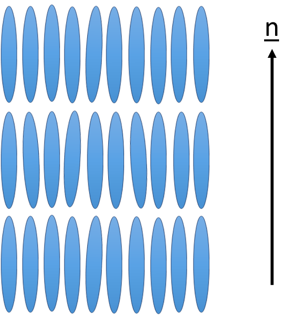 Figure 1: Smectic TLC, the vector n denotes the average direction of the long axis of the molecules.
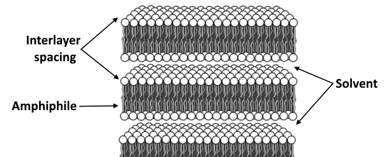 Figure 2: The structure of a lamellar lyotropic mesophase consists of surfactant bilayers separated by solvent.
A brief introduction to polarised light microscopy
Figure 2: The structure of a lamellar lyotropic mesophase consists of surfactant bilayers separated by solvent.
A brief introduction to polarised light microscopy
This report will investigate the applications of low cost polarised light microscopy (PLM) techniques for direct visualisation of molecular orientation inside a tribological contact. PLM is a contrast enhancing technique used to observe specimens that are visible due to optical anisotropy. A basic PLM transmission microscope is equipped with two crossed linear polarisers, one in the light path before the specimen, and a second polariser (
analyser) above the specimen. The high degree of long-range orientational order of lamellar LCs will give a highly anisotropic specimen which is optically uniaxial and strongly birefringent.
Birefringence is the optical property of a material that has a refractive index that depends on the propagation direction of the incident light and is measured as the maximum difference between the refractive indices of the material. Figure 3(a) shows a prolate spheroid model of a uniaxial liquid crystal molecule, birefringence of an LC sample is due to the index of refraction along the long axis (extraordinary axis, n
e) being different to the index of refraction perpendicular to the short axis (ordinary axis, n
o). The birefringence (B) is expressed by:
Birefringence (B) = |ne - no |
Plane polarised light incident on a birefringent sample is split into two mutually perpendicular planes. At the analyser the two wavefronts combine where the relative retardation (Γ) of the wavefront will give an interference colour reminiscent of the Michel-Lévy interference colour chart depending on the sample thickness (t) and birefringence. Retardation is expressed as:
Retardation (Γ) = t ∙ |ne-no |
As the incident light is polarised, any transmitted light that does not interact with a birefringent sample will be removed by the analyser (a linear polariser crossed relative to the incident light) leaving only the image from the interference with the anisotropic sample. For a sample of thickness
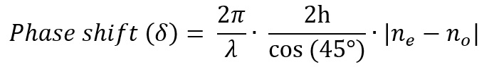
t the phase shift (δ) between the ordinary and extraordinary ray is expressed as:
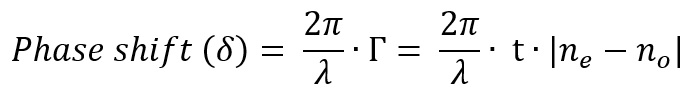
where λ is the wavelength of plane polarised light [13].
Figure 3(a) shows that plane polarised light incident on the axis corresponding to n
e. The wavefront only coincides with this refractive index and no birefringence will be observed, the light beam only interacts with n
o. Figure 3(b) shows how light incident on a LC molecule tilted in a shear flow will interact with two refractive indices, both the ordinary and extraordinary indices. This light will be subject to a birefringent effect and produce an image at the analyser demonstrating an anisotropic effect, and hence LC structure in the sample. A similar technique using shear induced polarised light imaging techniques has already been on a cone-and-plate rheometer for investigating polymeric and LC materials [14].
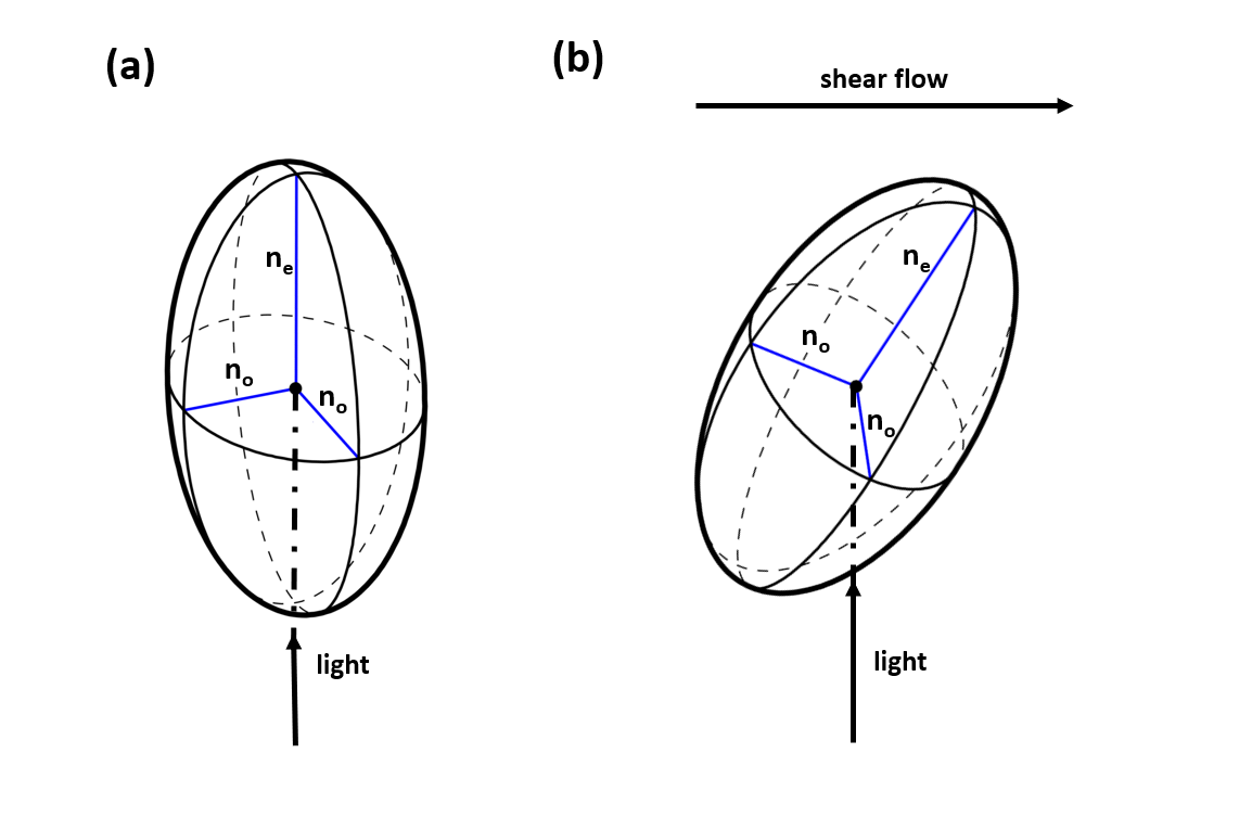 Figure 3: (a) optical indicatrix of a uniaxial liquid crystal where the semi axes correspond to the extraordinary (ne) and ordinary (no) refractive index with the incident light parallel to the extraordinary axis. This models a homeotropically aligned liquid crystal. (b) optical indicatrix of a uniaxial liquid crystal with a tilt towards the direction of shear with incident light oblique to the ordinary and extraordinary axes.
Materials and Methods
Materials
Figure 3: (a) optical indicatrix of a uniaxial liquid crystal where the semi axes correspond to the extraordinary (ne) and ordinary (no) refractive index with the incident light parallel to the extraordinary axis. This models a homeotropically aligned liquid crystal. (b) optical indicatrix of a uniaxial liquid crystal with a tilt towards the direction of shear with incident light oblique to the ordinary and extraordinary axes.
Materials and Methods
Materials
Two types of liquid crystals were used in these experiments; lamellar lyotropic LCs of triethanolammonium oleate with triethanolamine acting as the solvent [15]; and room temperature smectic 8CB TLCs. Room temperature lamellar lyotropic LCs of triethanolammonium oleate (TEOL) were prepared at ambient temperature directly from its constituents, oleic acid (reagent grade, > 99%) and triethanolamine (regent grade, > 99%) purchased from Sigma Aldrich in a 1.6:1 molar ratio. This lamellar LC was first reported by Friberg and has been confirmed to give a lamellar structure in this concentration [16, 15]. A thermotropic ambient temperature smectic LC 4'-n-Octyl-4-biphenylcarbonitrile (8CB) was purchased from TCI chemicals UK Ltd. The LC properties were confirmed using a research grade polarised light microscope and low angle XRD. Glycerol (reagent grade, > 99%) was purchased from Fischer-Scientific to be used as an optically isotropic control.
Perpendicular microscope setup
The Ultra-Thin Film Measurement System (PCS Instruments, UK) is a computer-controlled bench-top instrument for simultaneous measurement of friction coefficient and film thickness of lubricants in the elastohydrodynamic (EHD) lubricating regime. The instrument is capable of loads of 0 – 50 N, speeds of 0 – 4 ms
-1, and a slide/roll ratio from pure rolling up to pure sliding. The high pressures and velocity gradients in EHD contacts produce very high shear stresses that can promote alignment of LC molecules in and around the contact.
This instrument uses optical interferometry to measure ultra thin films in a Hertzian contact made between a transparent glass disc and a highly reflective AISI 52100 steel ball. Hence the tribometer is already equipped with a monoscope and a contact geometry designed for in situ microscopy and was determined to be a suitable test bed for mounting PLM to view LCs inside a tribological contact in a range of conditions. It is assumed that the glass disc is optically isotropic (i.e. not birefringent) and the reflection at the steel ball does not significantly contribute to the phase shift of the light, thus any birefringent effect observed is from the sample.
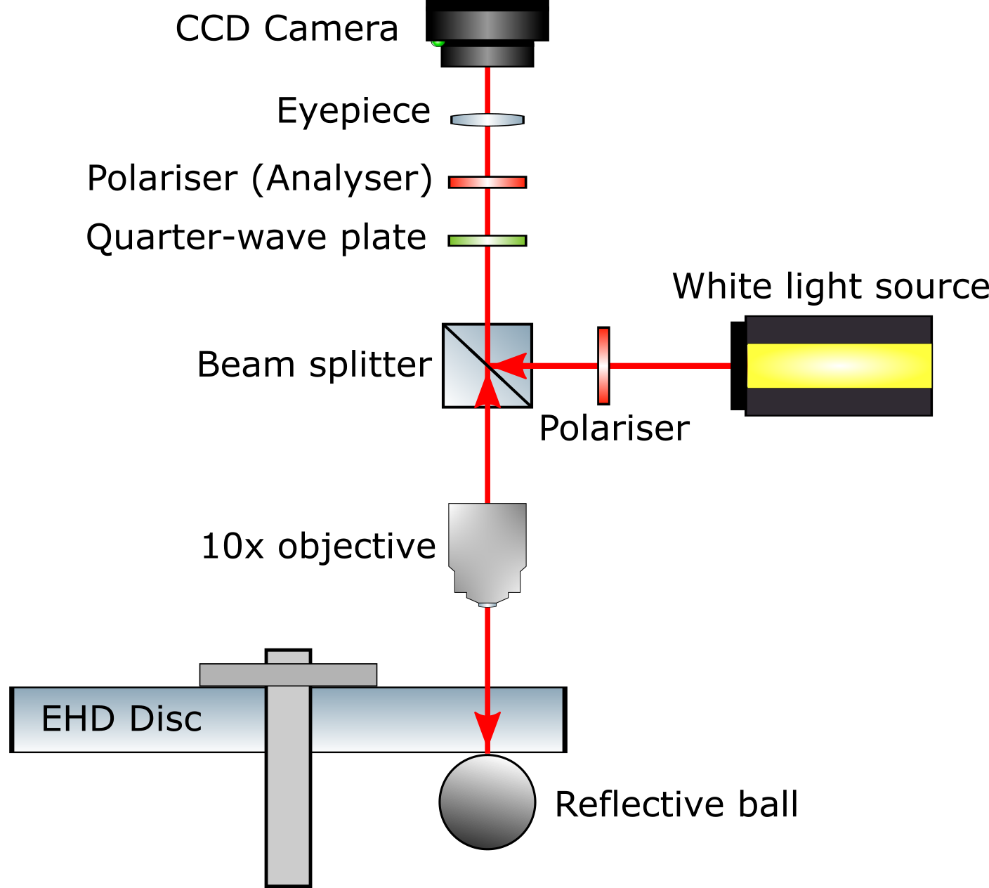 Figure 4: Schematic of optical components required for PLM on EHD tribometer.
Figure 4 shows a schematic of the optical components required to image LCs and is based on the components typically used to image birefringent specimens in a reflection mode. This setup uses a broad-band light source (a white halogen lamp). The contact is made between a plain glass EHD disc and reflective steel ball. The optical path is described as follows. The light passes through a polariser such that plane polarised light enters the beam splitter that is reflected down a 10x objective at 90° to the shear (contact) plane. The light is reflected at the steel ball and hence makes a double pass through the sample inside the contact. The light will then pass through the beam splitter up to the quarter wave plate, analyser (second linear polariser), and into the CCD camera.
If the lubricant sample is not birefringent then there will be no change of polarization state in the light reflected. This will not be transmitted through the analyser as the axis is orthogonal to the axis of light polarization and the image will be one of total extinction i.e. completely dark. With a birefringent sample the polarization state of the light will be rotated after passing through the sample. The light will be transmitted through the analyser and as the orientation of the axes of polarisation will be different to the orthogonal, an image showing birefringence will be produced.
A quarter waveplate (QWP) is included as a contrast enhancing technique in cases where the optical path is small, as the QWP will increase the path difference between the ordinary and extraordinary wavefronts. Furthermore, by aligning the fast and slow axes of the waveplate with the ordinary and extraordinary wavefronts it is possible to infer the alignment direction of the LCs. Here, the phase shift for the sample is expressed as:
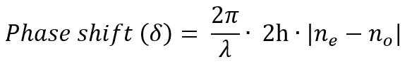
where
h is film thickness at that point (2h accounts for the light beam making a double pass).
Figure 5 shows a labelled diagram of the optical setup installed on the EHD tribometer. This setup will be used to detect shear alignment of LCs inside the EHD Hertzian contact. As the microscope is 90° to the contact (shear) plane no image will be produced if the sample inside is aligned homeotropically between the disc and the ball and to detect this a microscope mounted at an oblique angle is required.
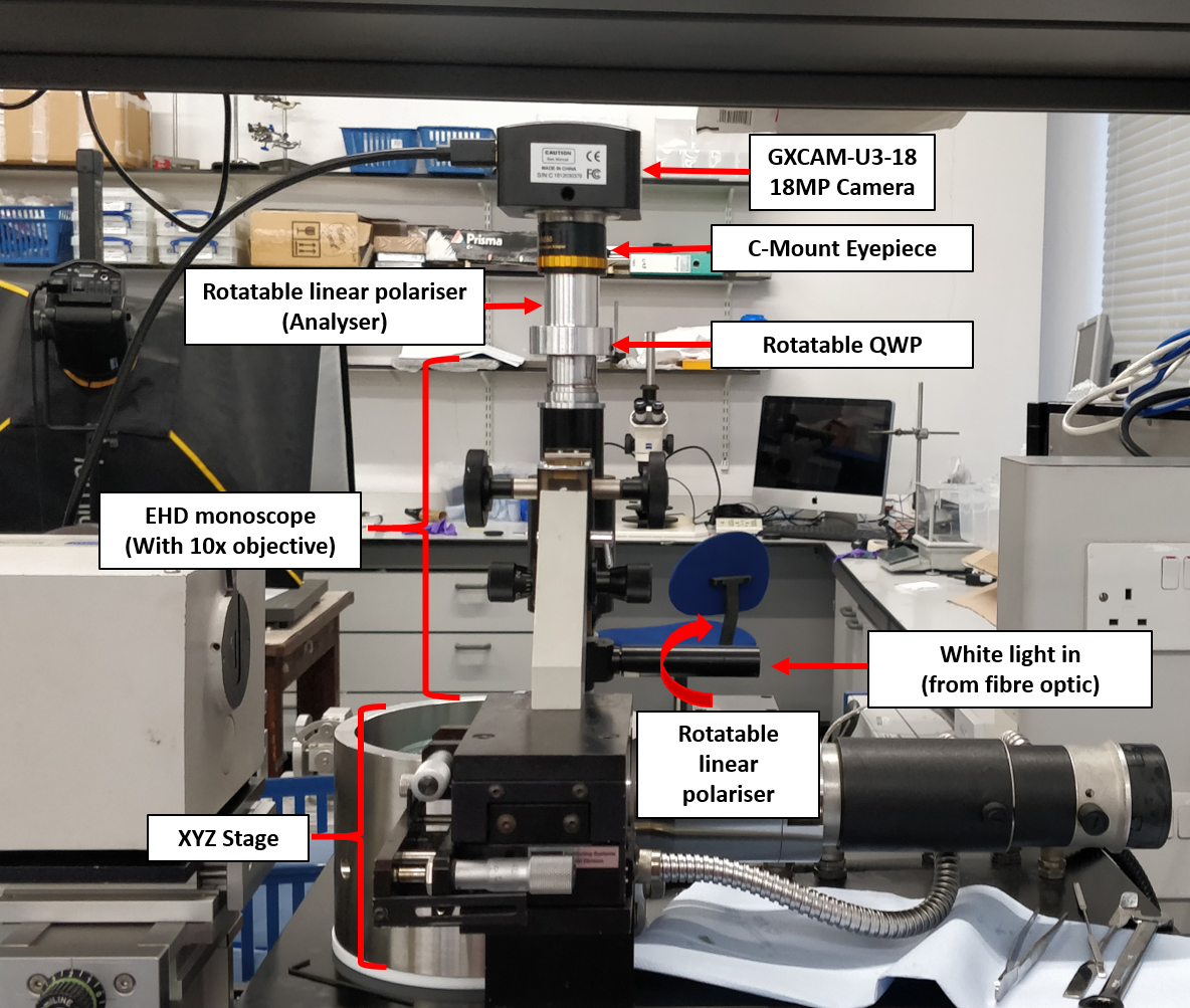 Figure 5: Labelled diagram of optical setup on EHD.
Oblique microscope setup
Figure 5: Labelled diagram of optical setup on EHD.
Oblique microscope setup
A second optical setup was developed, operating in the same way as the microscope previously described, but instead entering the contact at an oblique, 45° angle. Due to scattering and reflection effects at the air-glass interfaces a 633 nm (red) laser was employed as a much brighter light source was required. This setup was used to investigate LC samples in conditions that would promote the presence of homeotropically aligned structures in the contact (i.e. structures that would not display birefringence when viewed with the microscope normal to the contact).
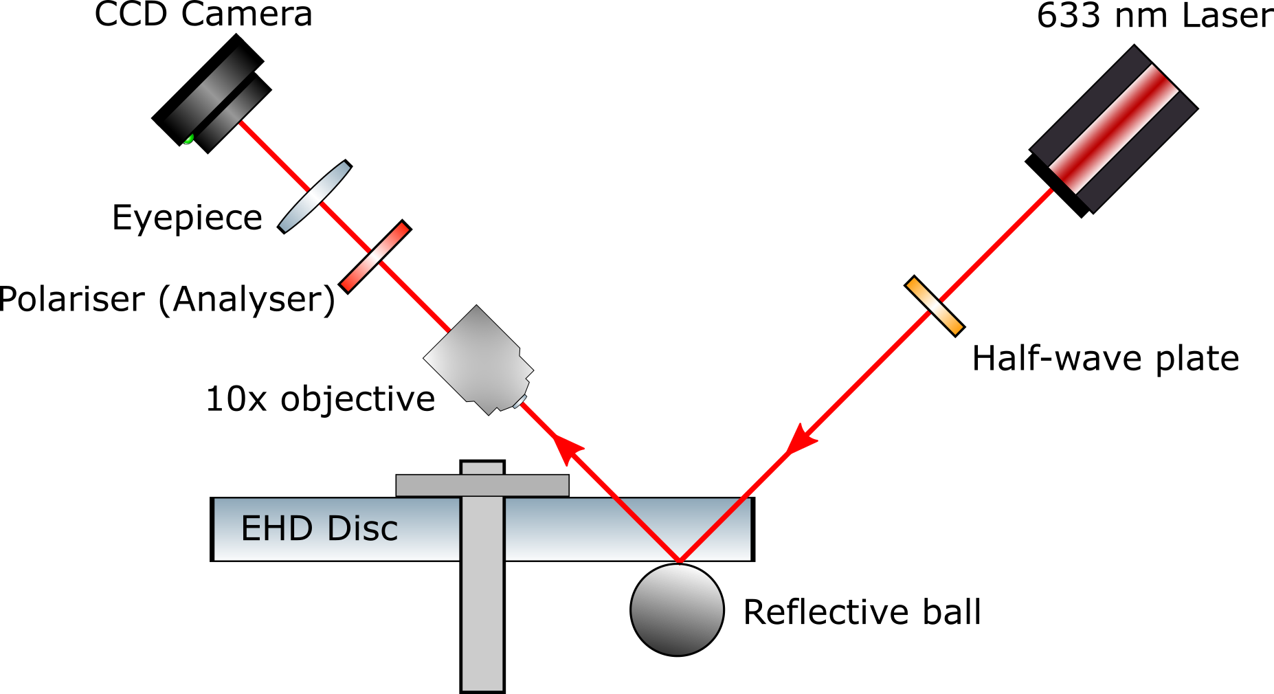 Figure 6: Schematic of optical components required for PLM at an oblique (45°) angle on the EHD tribometer.
Figure 6 shows a schematic of the optical components in the oblique microscope setup. The optical path is as follows. The 3 mW 633 nm HeNe laser emits polarised light, a half wave plate is used to rotate the plane of polarisation (in lieu of rotating the laser) to adjust LC image quality. Light enters the glass disc at a 45° angle, some light is reflected at the glass-air interface, but a sufficiently bright beam enters the glass disc and LC sample through a 10x objective. The light is reflected at the small flat central area of the Hertzian contact at 45°, through the disc, and into a second polariser (analyser) with an axis orthogonal to the laser output polarisation. This then passes into a CCD camera and lens to focus the image onto the CCD chip. The phase shift for this geometry is expressed as:
where
h is the film thickness at that point, the
factor comes from the double light pass through the sample at an angle of 45°.
As monochromatic light (laser) is used a colourful interference pattern is not possible. In cases where the sample is not birefringent there will be no change in the state of polarisation and the light will stop at the analyser, producing no image in the Hertzian contact. If the sample is birefringent then the state of polarisation will be rotated, and light will pass through the analyser producing an image inside the Hertzian contact area. Figure 7 shows a labelled diagram of this setup installed on the EHD tribometer.
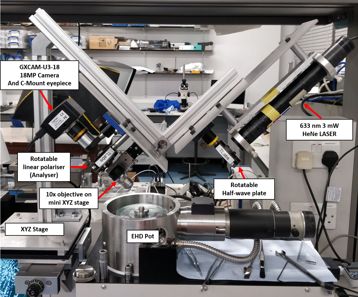 Figure 7: Labelled diagram of oblique microscope used on EHD.
Results and Discussion
Lubricants characterisation
Figure 7: Labelled diagram of oblique microscope used on EHD.
Results and Discussion
Lubricants characterisation
At 25 °C TEOL and 8CB were in a lamellar phase. Small amounts of each LC sample were placed on glass slides and viewed through a microscope equipped with crossed polarisers. The PLM images of TEOL and 8CB are shown in Figures 8 and 9 respectively. Both samples show a characteristic streaky texture indicative of a lamellar phase [17, 16].
Low angle x-ray diffraction measurements confirmed the TEOL mixed at a 1:1.6 triethanolamine and oleic acid molar ratio has a lamellar structure with an interlayer spacing of 38 Å, this is indicated by a clear peak around 2.6° shown in Figure 10.
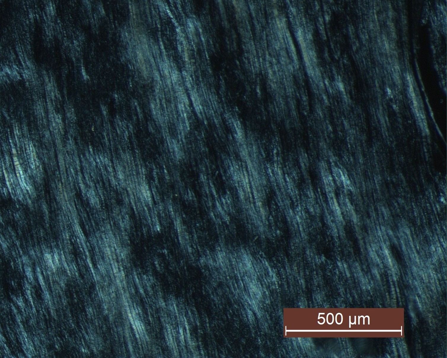 Figure 8: PLM image showing optical pattern of lamellar LLC TEOL at 25 °C, note the 'oily streak' texture characteristic of a lamellar lyotropic liquid crystal phase.
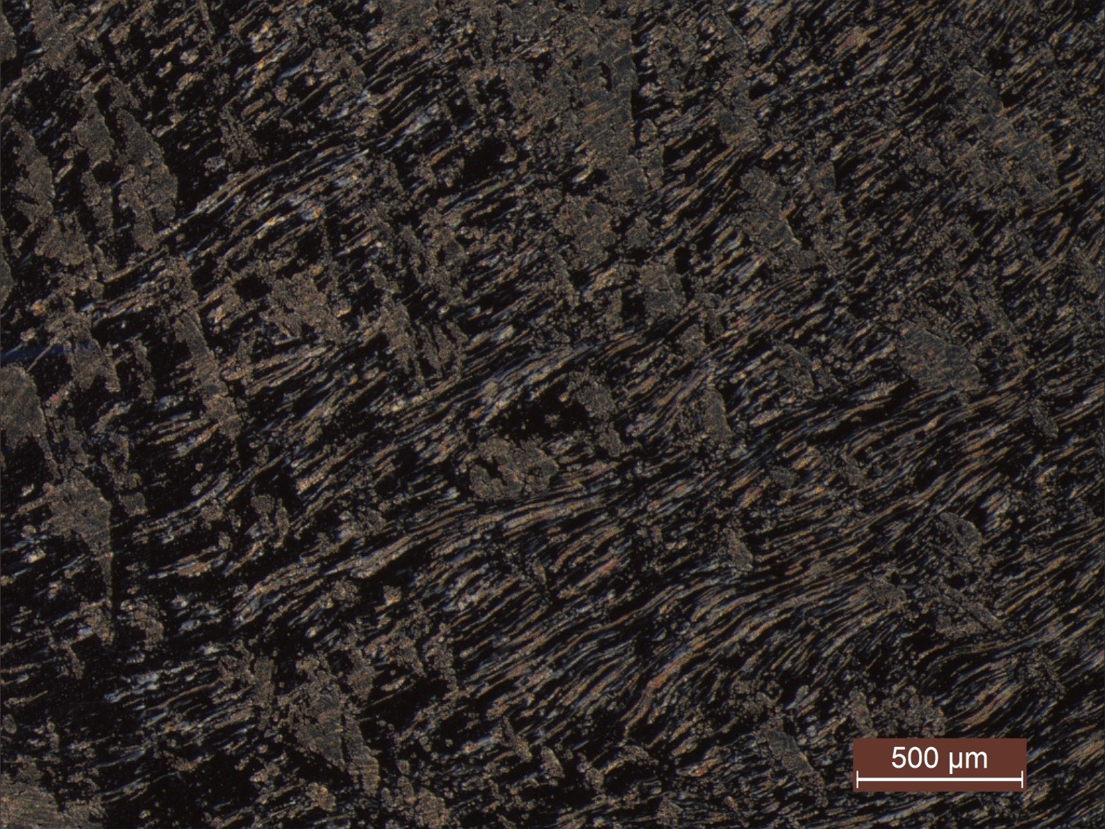 Figure 9: PLM image showing optical pattern of smectic 8CB at 25 °C.
 Figure 10: Low angle X-ray diffraction measurements showing a clear peak at 2.6° which corresponds to an interlayer spacing of 38 Å. A second smaller peak can be seen around 5.2° which corresponds to 19 Å, the height of half a bilayer.
Perpendicular microscope experiments
TEOL LC
Figure 10: Low angle X-ray diffraction measurements showing a clear peak at 2.6° which corresponds to an interlayer spacing of 38 Å. A second smaller peak can be seen around 5.2° which corresponds to 19 Å, the height of half a bilayer.
Perpendicular microscope experiments
TEOL LC
A small amount of TEOL was placed between the steel ball and glass disc of the EHD tribometer. As the static load is increased the LC is observed to align radially towards the centre of the contact, the point of the highest load. Figures 11(a), (b) and (c) show this transition as the load is increased to 20 N. In the absence of the load [Fig. 11(a)] the TEOL appears isotropic when viewed through the microscope showing the sample is not aligned. As the load is increased to 3 N [Fig. 11(b)] a Maltese cross strain pattern becomes noticeable around the Hertzian contact, when the principal directions of the hemispherical stress pattern in the glass form a zero angle with the polariser or analyser axis isogyres appear resulting in the Maltese cross pattern [18]. This is not the result of the birefringent sample as a similar Maltese cross stress pattern can be seen with optically isotropic glycerol [Fig 11(d)].
Above 3 N a sudden transition is observed where the TEOL align radially towards the centre of the Hertzian contact. As load is increased the observed alignment does not change significantly; increasing the load only increases the size of the contact. This alignment is demonstrated in Fig 11(c) at a load of 20 N, corresponding to a maximum contact pressure of 0.51 GPa. This image is composed of two distinct regions; the dark centre of the image including the Hertzian contact and the surrounding dark area; and the area populated with yellow and blue domains of birefringent LC structures. In static conditions there is only a very thin squeeze film inside the Hertzian contact area, so thin that it would not interact significantly regardless of the LC orientation. The dark area surrounding the HC indicates an area where the lamellae are orientated with their layer normal parallel to the glass surface (aligned homeotropically and light orthogonal to the lamellar planes will not experience a birefringent effect). High pressures have been shown to promote highly ordered homeotropic alignment of lyotropic, lamellar structures [19]. This will be further investigated with the oblique microscope.
LC structures become visible approximately 400 µm from the centre of the HC, this is an area where the pressure on the fluid is substantially lower and the fluid film is thicker. The visible LC structures are aligned radially and correspond to lamellae with a layer normal at a tilted or perpendicular angle to the incident light. The yellow and blue colours are a result of interactions at the fast and slow axis of the QWP. There is no noticeable gradient of birefringence indicating that all the lamellae are orientated by the same degree which would suggest the lamellae are orientated with the layer normal perpendicular to the incident light. A very similar well-defined boundary has been observed for lamellar phase LCs induced by a critical shear rate in work done by Mykhaylyk et al [14]. In this case the transition has been induced by a critical pressure.
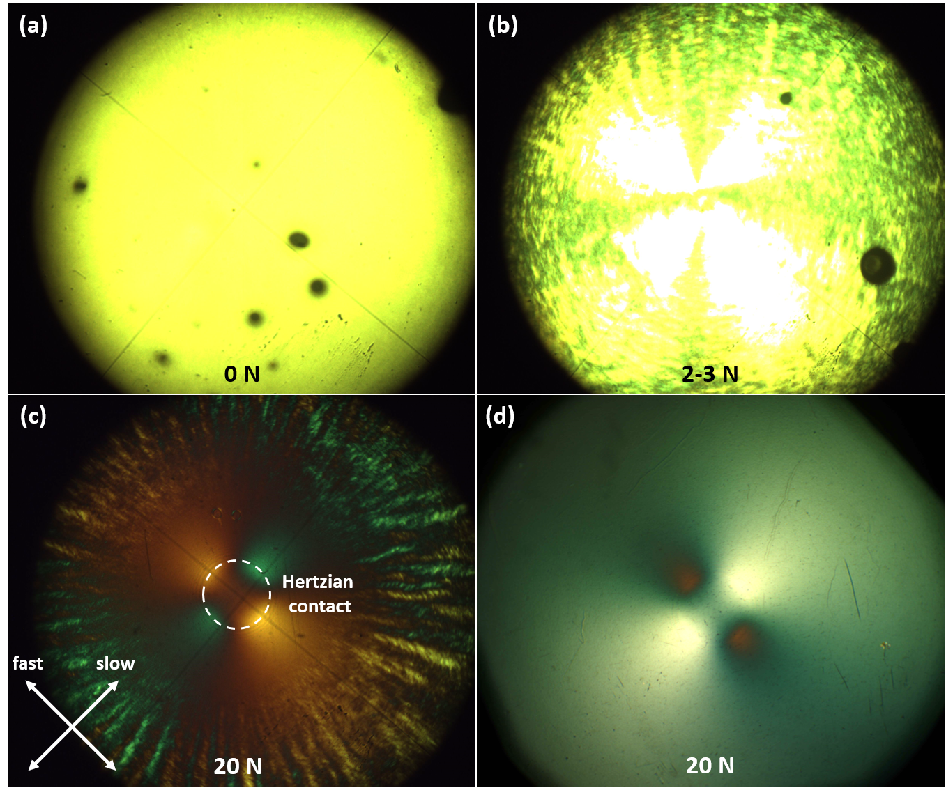 Figure 11: Static alignment of TEOL (between a glass disc and steel ball) as load is increased from 0 to 20 N (a) no contact, 0 N (b) isotropic stress pattern begins to appear as load is increased from 2 to 3 N (c) radial alignment of TEOL around Hertzian contact, the fast and slow axis of the QWP are marked. (d) glycerol viewed through the same setup at 20 N, a stress pattern is still visible around the Hertzian contact.
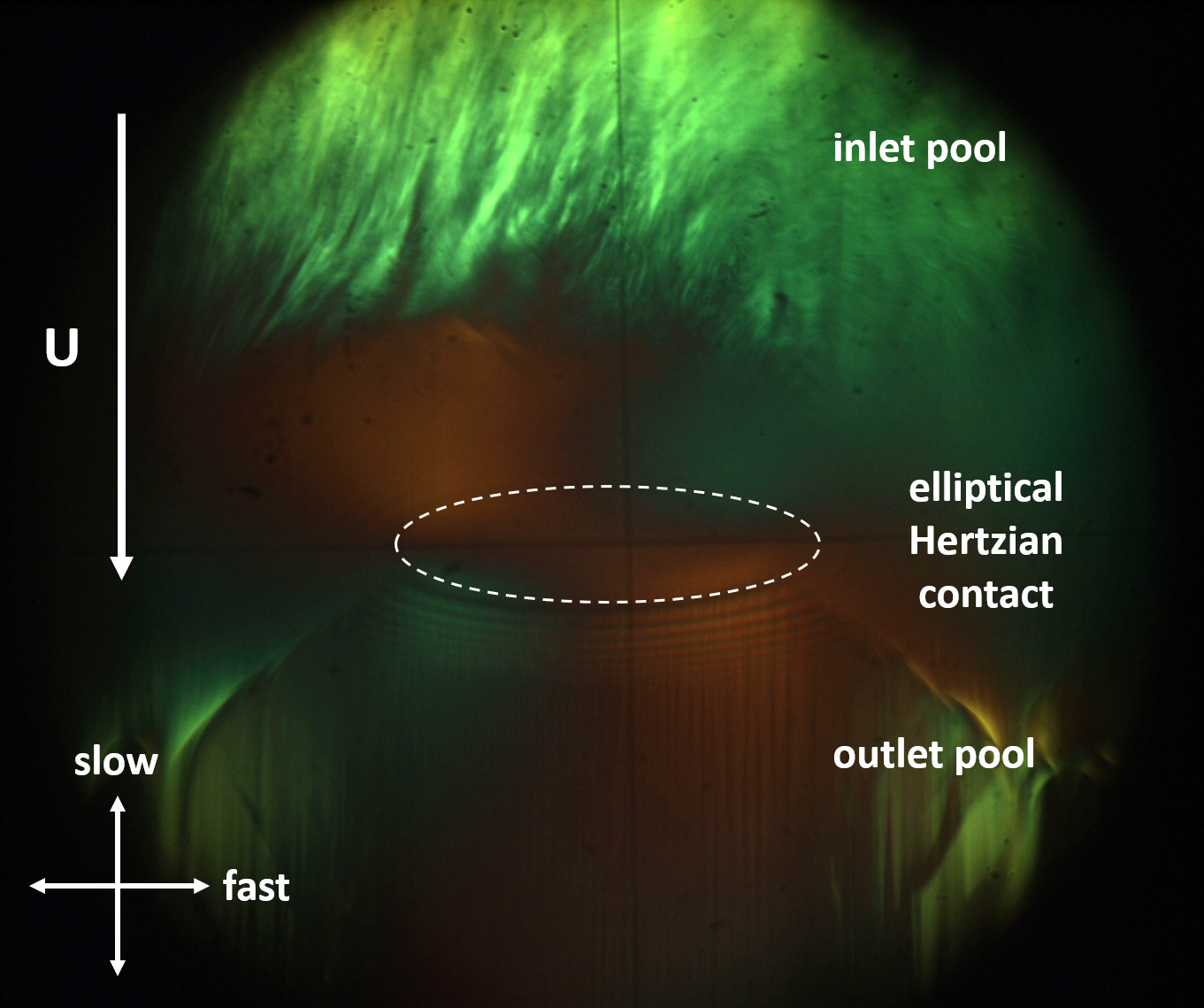 Figure 12: Annotated image of elliptical Hertzian contact showing TEOL alignment along the entrainment direction (U). The inlet pool, HC area, outlet pool, and axes of the QWP are marked.
Figure 12 shows an annotated image of a TEOL lubricated elliptical EHD contact in dynamic conditions (20 mms
-1 with a 50% SRR and 20 N load). Interesting information for TEOL in this setup is visualised in the inlet and outlet pools of the EHD contact where birefringent structures are visible. By using a larger size elliptical contact, the contact pressure in and around the contact is lower at the same applied (20 N) load and the front of the visible LC appears closer to the HC area. However, the elliptical roller used in this contact geometry was not fixed about its transverse axis and at high speeds would oscillate slightly leading to obscured blurry images of the HC. In Figure 12 faint Newton rings can be observed below the contact but this detail is lost at speeds above 50 mms
-1.
Figure 13 shows TEOL behaviour in a range of speeds with a 20 N load and 50% SRR. At low speeds [Figures 13(a) and 13(b)] show the inlet pool contains separated domains of alignment with only some of the LC structure appearing light blue along the slow axis of the QWP. As speed is increased to 20 mms
-1 [Fig 13(c)] the LC in the inlet pool align homogenously in the entrainment direction with a much more stable flow. Figure 14 shows an enlarged image of the of the inlet at 5 mms
-1 and 20 mms
-1.
At higher speeds [Figures 13(d) and 13(e)] the entrainment direction dominates the LC alignment in the inlet pool up to speeds of around 200 mms
-1 at which point the homogenous alignment began to break down at the entry of the inlet pool [Fig 13(f)]. This is characterised by dark spikes appearing demonstrating a definite change in LC structure in this region, a gradient of colour is seen indicating that this feature is still birefringent and therefore structured. Whilst it is not shown in this figure, the appearance of these spikes consistently preceded starvation, though the exact structural significance of these features is unknown.
These tests were repeated for a state of pure rolling (0% SRR) and pure sliding (100% SRR). At low speeds (5 – 20 mms
-1) an increase in sliding (SRR) leads to homogenous TEOL alignment in the contact inlet at lower speeds. In the case of 100% SRR complete alignment was observed in the inlet at a speed of 10 mms
-1. This further demonstrates lamellar LCs sensitivity to shear.
In all tests no birefringence effect was observed inside the HC which suggests the structure inside the contact is homeotropically aligned as light orthogonal to lamellar planes will experience no birefringence.
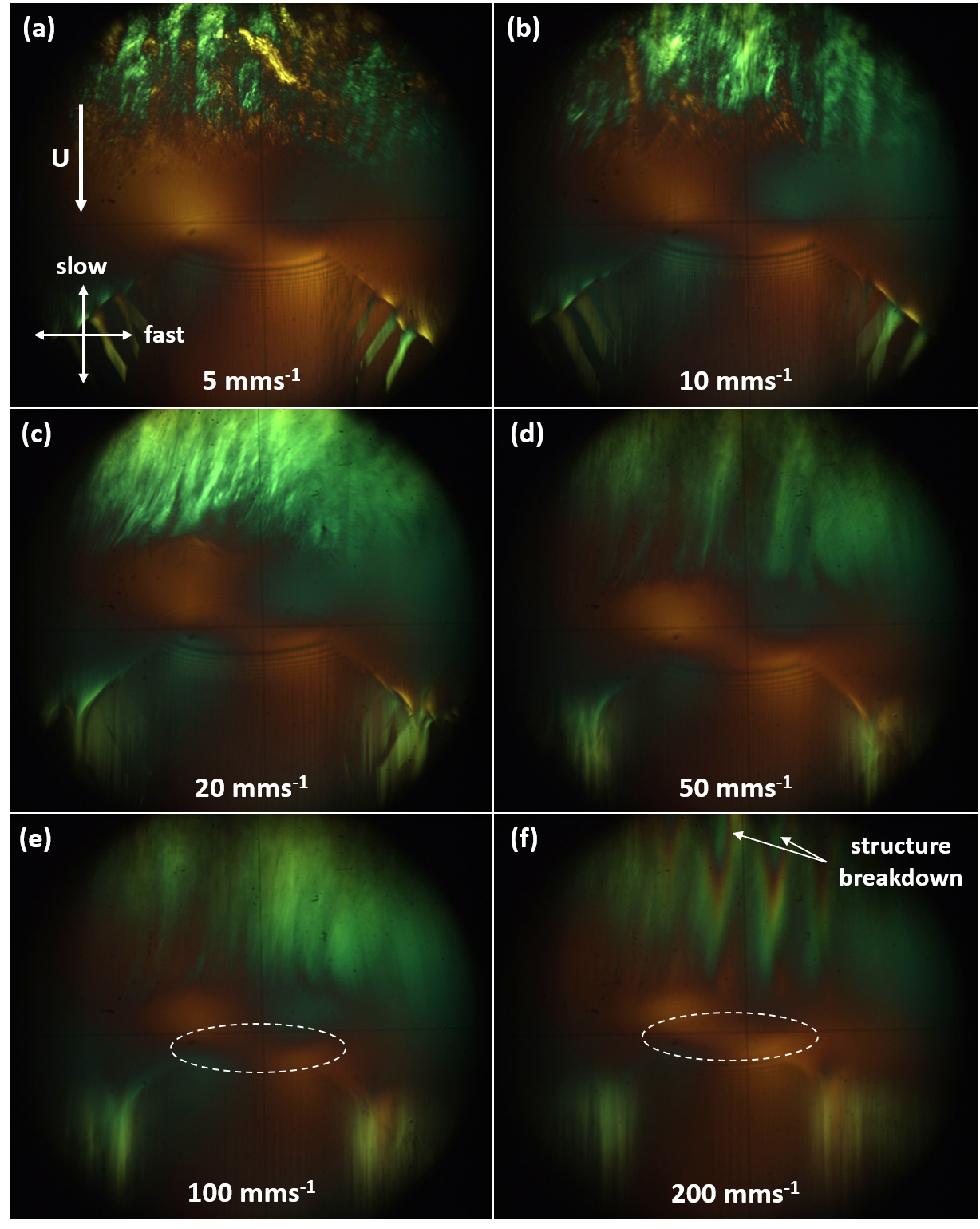 Figure 13: Images of elliptical EHD contact lubricated with TEOL at 20 N, 50% SRR at speeds of (a) 5 mms-1 (b) 10 mms-1 (c) 20 mms-1 (d) 50 mms-1 (e) 100 mms-1 (f) 200 mms-1. The entrainment direction and QWP axes are marked on (a) and is the same for each case. The white dashed ellipses indicate the location of the HC in (e) and (f).
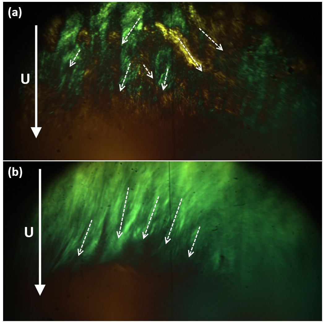 Figure 14: Enlarged images of inlet pool of EHD contact lubricated with TEOL at 20 N, 50% SRR, at (a) 5 mms-1 and (b) 20 mms-1.
8CB LC
Figure 14: Enlarged images of inlet pool of EHD contact lubricated with TEOL at 20 N, 50% SRR, at (a) 5 mms-1 and (b) 20 mms-1.
8CB LC
Figure 15 shows a sample of 8CB in an elliptical HC under a load of 20 N in static conditions. The HC is obscured by a reflection effect at the 8CB-glass interface, and the location of the HC is circled by a dashed white line. The colours immediately above and below the HC are consistent with first, second, and third order interference colours with no QWP inserted [20]. 8CB has been shown to maintain a homeotropic structure up to pressures above 250 MPa, even displaying a pressure induced layer expansion [21].
The area inside the HC displays no birefringence which is expected in static conditions as the squeeze film will have a thickness on the order of nanometres and will not noticeably change the state of light polarisation. The interference colour gradient outside the contact shows the 8CB smectic structure is orientated uniformly towards the contact. Outside this area the LC tilt appears to lose uniformity.
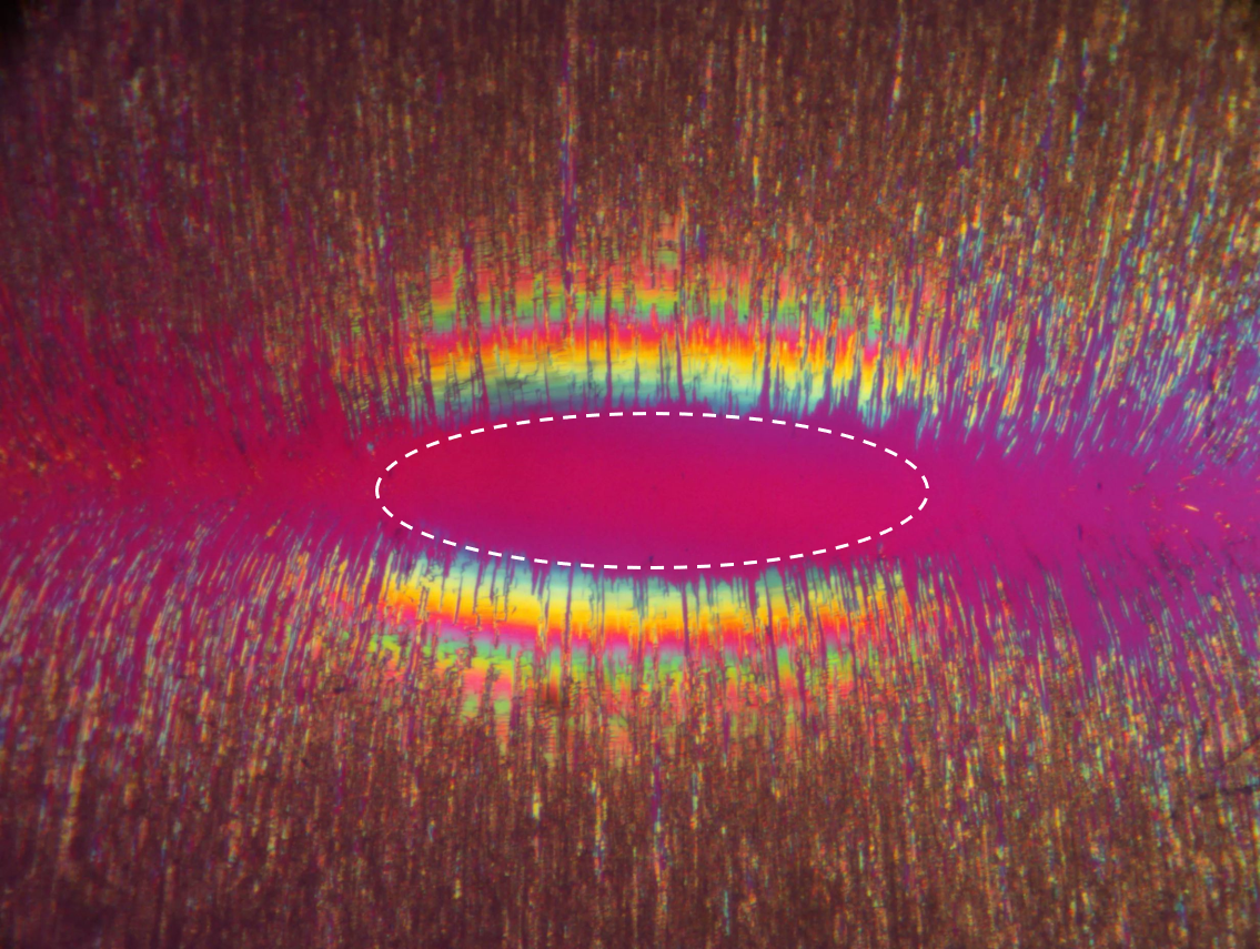 Figure 15: Static elliptical HC lubricated with 8CB at 20 N (max contact pressure 0.3 GPa), the white dashed line indicates the obscured HC area. NB: QWP is removed.
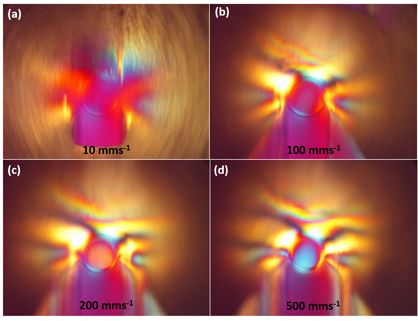 Figure 16: Images of 8CB in a circular point HC at 20 N, 50% SRR at speeds of (a) 10 mms-1 (b) 100 mms-1 (c) 200 mms-1 (d) 500 mms-1. NB: QWP is removed.
In dynamic conditions a birefringent effect is observed inside the HC area. At low speeds and 10 mms
-1 and 100 mms
-1 [Fig 16(a) and 16(b) respectively] very little birefringence is noted inside the contact. As speed increased to 200 mms
-1 [Fig 16(c)] an orange colour inside the HC indicates a birefringent effect. At even higher speeds of 500 mms
-1 [Fig 16(b)] the area inside the HC turns light blue. The QWP was removed in these tests so the images could be compared against an interference colour chart but this shift in colour was not found to match a standard interference colour scale. However, this effect can only be attributed to a birefringent effect, and the colour change due to an increase in retardation as the film thickness increases with speed in the HC. These results demonstrate that at high speeds the lamellar normal of 8CB tilts towards (or lies parallel to) the entrainment velocity vector. This observation is consistent with other studies that have used in situ Raman spectroscopy [9, 22] and FTIR [7] to show that C biphenylcarbonitrile (CB) structures align parallel to the shearing plane in a HC zone.
For comparison, contact images from the same test conditions (with no QWP) are shown for TEOL in Figure 17. In these tests no birefringent effect was observed inside the HC irrespective of speed.
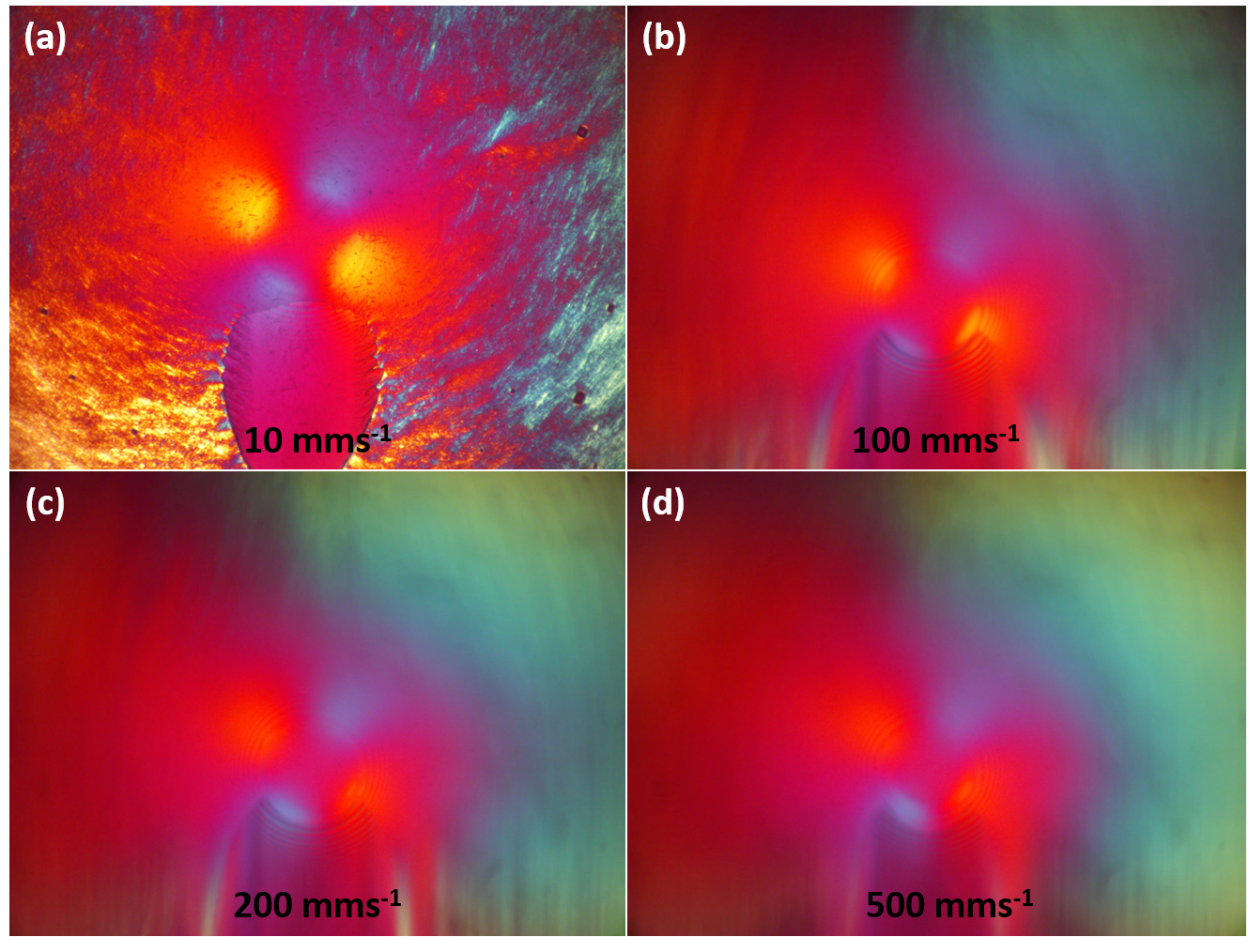 Figure 17: Images of TEOL in a point HC (QWP removed) at 20 N, 50% SRR at speeds of (a) 10 mms-1 (b) 100 mms-1 (c) 200 mms-1 (d) 500 mms-1.
Oblique microscope experiments
Figure 17: Images of TEOL in a point HC (QWP removed) at 20 N, 50% SRR at speeds of (a) 10 mms-1 (b) 100 mms-1 (c) 200 mms-1 (d) 500 mms-1.
Oblique microscope experiments
An oblique microscope setup was mounted on the EHD tribometer to investigate the presence of LC structures that are aligned homeotropically in the contact. This case cannot be detected with a microscope normal to the contact as incident light orthogonal to the lamellar planes will not experience birefringence. When the microscope is set at an oblique angle, in this case 45°, structures aligned homeotropically will display birefringence when the light ray is incident on the ordinary and extraordinary refractive index axes.
Due to undesired reflection effects at the glass-air and the glass-lubricant interfaces a very high intensity light source was required to image the HC. A 633 nm (red) 3 mW HeNe laser was an appropriate intensity. However, it was found that using a laser gave some undesired speckle patterns and other noise in the image due to imperfect extinction at the analyser. Images were taken at speeds of 10, 100, 200, and 500 mms
-1.
Reference images were taken using optically isotropic glycerol as the test lubricant. Figure 18(a) – 18(d) show these images which will be used as a control to identify the presence of birefringent effects for the TEOL and 8CB. At low speeds [Fig 18(a)] a clear Maltese cross is observed due to the deformation of the glass; the centre of the contact appears black indicating there is no phase shift in the light reflected from the ball. As speed increased [Figures 18(b) – 18(d)] the centre of the HC remains dark, some light is reflected back and reaches the camera due to subtle imperfections in the optical alignment.
Images for TEOL are shown in Figures 18(e) – (h); at all speeds no significant birefringent effect is noted inside the HC area when compared to the control images taken with glycerol in the contact [Figures 18(a) – 18(d)]. At a speed of 500 mms
-1 the measured film thickness using optical interferometry was approximately 102 nm, which would give an optical path length of approximately 288 nm (
t =  = 288 nm, where h = 102 nm
). If the LC structure was homeotropically aligned in the contact, as suggested by the previous experiments [Fig 13] with the microscope normal to the contact, a noticeable birefringent effect would be expected. This leaves two cases (i) there is no structure at the contact or (ii) the optical anisotropy of the sample is sufficiently small that the phase shift of the light is small. Previous work by Lockwood et al which studied this TEOL system in an EHD contact through film thickness, friction, and rheological testing were not confident in concluding the presence of homeotropic alignment in the contact [23]. This would support case (i) that concludes the LC is not aligned homeotropically in the contact and would even suggest there is no long-range order inside the HC. There is still uncertainty about TEOLs unusual lubricating properties due to the lamellar liquid crystal structure reported in [23, 24]. Case (ii) is not worth dismissing and should be the subject of further study by measuring the TEOL optical anisotropy.
8CB displayed a clear birefringent effect inside the HC in these tests [Figures 18(i) – 18(l)] when compared to the control images taken with glycerol [Figures 18(a) – 18(d)]. The birefringence inside the HC only becomes noticeable at speeds of 100 mms
-1 [Fig 18(j)] as the film thickness increases to give an optical path length that gives a noticeable birefringent effect. This is characterised by an intense reflection at the centre of HC with a sufficient phase shift such that it is not extinct by the analyser. As the speed, and hence the film thickness and optical path length, increases the intensity of the reflection increases [Figures 18(k) and 18(l)]. This result confirms that the 8CB sample is tilted or parallel to the entrainment velocity vector considering the birefringence seen with the normal microscope [Fig 16].
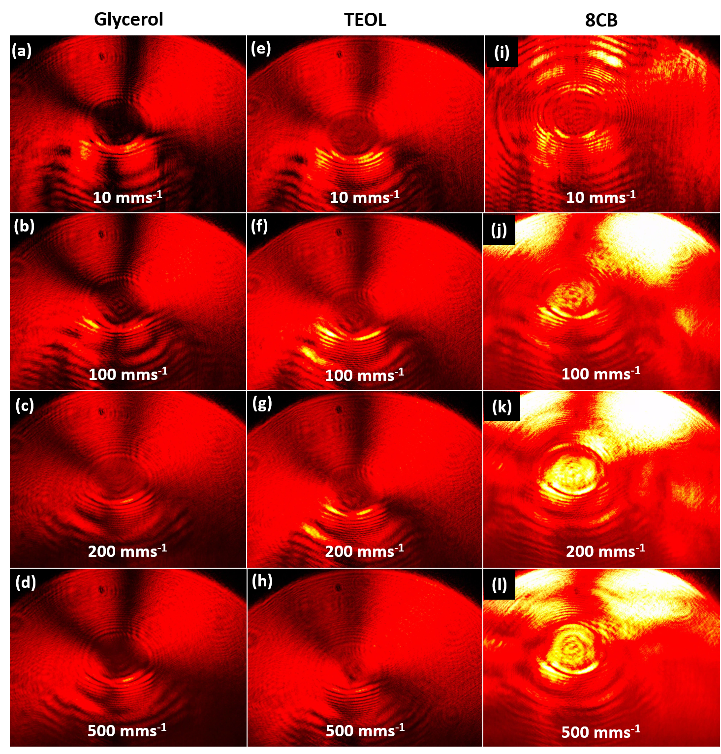 Figure 18: PLM at an oblique (45°) angle to a circular HC at a load of 20 N, 50 % SRR, and speeds of 10 mms-1, 100 mms-1, 200 mms-1, 500 mms-1 imaging samples of glycerol (a) – (d), TEOL (e) - (h) and 8CB (i) – (l).
Conclusions
Figure 18: PLM at an oblique (45°) angle to a circular HC at a load of 20 N, 50 % SRR, and speeds of 10 mms-1, 100 mms-1, 200 mms-1, 500 mms-1 imaging samples of glycerol (a) – (d), TEOL (e) - (h) and 8CB (i) – (l).
Conclusions
A low-cost technique has been developed that can produce high contrast images of the flow behaviour and molecular alignment of structured birefringent lubricants in high pressure tribological contacts. The method described is appropriate for
in lubro investigations of anisotropic liquid crystal lubricants under different conditions of shear, pressure, entrainment speeds, and temperature. This method is capable of simultaneous friction measurement and birefringence imaging, while the optical setup can quickly be modified to perform film thickness measurements using thin film interferometry. With the use of two microscope setups, a perpendicular and oblique setup, it is possible to investigate the presence of homeotropically aligned liquid crystals by comparing results from each geometry.
This provides a powerful set of methods for investigating the relationship between LC molecular orientation and tribological properties. The setup is limited to a transparent optically isotropic disc specimen (i.e. glass) but a range of reflective ball specimens can be used (e.g. CoCr). A future publication will describe the use of these methods to understand the behaviours of liquid crystal forming biomolecules.
The performance and applications of this method was tested with TEOL and 8CB, both of which are liquid crystalline with a lamellar structure. The observed behaviour of 8CB with the normal and oblique microscope shows that they tilt towards the entrainment velocity vector, a finding that is consistent with published results using other techniques. TEOL did not show birefringence inside the HC under the perpendicular or oblique microscope which suggests the LC does not align homeotropically inside the contact area. This may be due to the low birefringence of TEOL, so a thicker film may be required to determine the TEOL structure at the contact. This method was successful for gaining a new understanding of TEOL lubricant flow in the contact inlet and for characterising the molecular alignment dependence on speed and shear.
This technique has an excellent potential to go beyond the work that has been described in this report. Experimental studies of the molecular alignment of lubricants has been growing rapidly in recent years with many developments in Raman spectroscopy, FTIR spectroscopy, and XRD in the context of tribology for determining in situ molecular alignment. PLM techniques are a complimentary, visual, low cost method for developing new structured lubricants and determining their molecular configuration, conformation, and orientation in and around tribological contacts.
Acknowledgements
RJE would like to thank the STLE for honouring him with the E. Richard Booser Scholarship which sponsored this research. He is grateful to his project supervisors, Dr. Monica Ratoi and Dr. Brian Mellor for their guidance, support, and encouragement during this project. Additionally, he is thankful for the support from Professor Peter Dobson (Oxford University, UK) and Matthew Delaney (Optoelectronics Research Centre, University of Southampton, UK) for help sourcing and developing the optical setups in this project.
References
[1] G. Biresaw, “Tribology and the liquid-crystalline state,” 1990.
[2] F. J. Carrión, G. I. P. Martinéz-Nicolás, J. Sanes and M.-D. Bermúdez, “Liquid crystals in tribology,”
International journal of molecular sciences, vol. 10, no. 9, pp. 4102-4115, 2009.
[3] K. Boschkova, J. Elvesjo and B. Kronberg, “Frictional properties of lyotropic liquid crystalline mesophases at surfaces,”
Cooloids and Surfaces A: Physiochemical and Engineering Aspects, vol. 166, no. 1-3, pp. 245-269, 2000.
[4] T. J. Sluckin, “The liquid crystal phases: physics and technology,”
Contemporary Physics, vol. 41, no. 1, pp. 37-56, 2000.
[5] S. Hollinger, J. M. Georges, D. Mazuyer, G. Lorentx, O. Aguerre and N. Du, “High-pressure lubrication with lamellar structures in aqueous lubricant,”
Tribology Letters, vol. 9, no. 3-4, pp. 143-151, 2000.
[6] J. Cognard, “Lubrication with Liquid Crystals, in Tribology and the Liquid Crystalline State,”
ACS Symposium, vol. 441, pp. 1-47, 1990.
[7] S. Mori and H. Iwata, “Relationship between tribological performance of liquid crystals and their molecular structures,”
Tribology International, vol. 29, no. 1, pp. 35-39, 1996.
[8] Y. Kim, M. Lee, H. S. Wang and K. Song, “The effect of surface polarity of glass on liquid crystal alignment,”
Liquid Crystals, vol. 45, 2018.
[9] M. Gao, H. Li, L. Ma, Y. M. L. Gao and J. Luo, “Molecular behaviours in thin film lubrication - Part two: direct observation of the molecular orientation near the solid surface,”
Friction, vol. 7, no. 5, pp. 479-488, 2019.
[10] T. E. Fischer, S. Bhattacharya, R. Salher, J. L. Lauer and Y. J. Ahn, “Lubrication by a smectic liquid crystal,”
Tribology Transactions, vol. 31, no. 4, pp. 442-448, 1988.
[11] L. Ma and J. Luo, “Thin film lubrication in the past 20 years,”
Friction, vol. 4, no. 4, pp. 280-302, 2016.
[12] P. M. Cann, M. J. G. J. Aderin and H. A. Spikes, “Paper V (iii) An Investigation into the Orientation of Lubricant Molecules in EHD contacts,”
Wear Particles, vol. 21, pp. 209-218, 1992.
[13] M. Born and E. Wolf, Principles of Optics: Electromagnetic Theory of Propogation, Interference and Diffraction of Light, Cambridge: Cambridge University Press, 1999.
[14] O. O. Mykhaylyk, N. J. Warren, A. J. Parnell, G. Pfeifer and J. Laeuger, “Applications of Shear-Induced Polarized Light Imaging (SIPLI) technique for Mechano-Optical Rheology of Polymers and Soft Matter Materials,”
Polymer Physics, vol. 54, pp. 2151-2170, 2016.
[15] S. E. Friberg, C. S. Wohn and F. E. Lockwood, “The Influence of Solvent on Nonaqueous Lyotropic Liquid Crystalline Phase Formed by Triethanolammonium Oleate,”
Journal of Pharmaceutical Sciences, vol. 74, no. 7, pp. 771-773, 1985.
[16] S. E. Friberg and P. Liang, “Single compound forming a lyotropic liquid crystal at room temperature,”
Journal of physical chemistry, vol. 88, pp. 1045-1046, 1984.
[17] I. Dierking, Textures of Liquid Crystals, Weinheim: WILEY-VCH, 2003.
[18] J. Lekner, “Isogyre formation by isotropic refracting bodies,”
Ophthalmic and Physiological Optics, vol. 15, no. 1, pp. 69-72, 1995.
[19] R. Winter and C. Jeworrek, “Effect of pressure on membranes,”
The Royal Society of Chemistry, vol. 5, pp. 3157-3173, 2009.
[20] B. E. Sørensen, “A revised Michel-Lévy interference colour chart based on first-principles calculations,”
European Journal of Mineralogy, vol. 25, no. 1, pp. 5-10, 2013.
[21] J. Przedmojski, J. Jedrzejewski, R. Dabrowski, K. Czupryński, W. Tłaczała and R. Wiśniewski, “X-ray investigation of 8CB and 8OCB under high pressure,”
Phase Transitions: A Multinational Journal, vol. 56, no. 2, pp. 119-126, 1996.
[22] S. Zhang, Y. Liu and J. Luo, “In situ observation of the molecular ordering in the lubricating point contact area,”
Journal of Applied Physics, vol. 116, p. 014302, 2014.
[23] F. E. Lockwood, M. T. Benchaita and S. E. Friberg, “Study of Lyotropic Liquid Crystals in Viscometric Flow and Elastohydrodynamic Contact,”
A S L E Transactions, vol. 30, no. 4, pp. 539-548, 1986.