Numerical modeling of tribological systems
Jeanna Van Rensselar, Senior Feature Writer | TLT Webinars June 2018
Despite a few limitations, computer-aided modeling is a significant time- and money-saving option for lubrication engineers.
© Can Stock Photo / nerthuz
KEY CONCEPTS
•
Numerical modeling capabilities are very strong for general components.
•
The introduction of tribological aspects into a model tends to introduce complications often neglected by commercial software.
•
To avoid erroneous predictions, proper execution and methodology is essential when using numerical methods.
MEET THE PRESENTER
This article is based on a Webinar originally presented by STLE Education on July 19, 2017.
Computer Aided Modeling in Tribology is available at
www.stle.org: $39 to STLE members, $59 for all others.
Dr. Robert L. Jackson is a professor of mechanical engineering at Auburn University in Auburn, Ala. He received his doctorate in mechanical engineering at the Georgia Institute of Technology in Atlanta. At Auburn Jackson established the Multiscale Tribology Laboratory, which focuses on the areas of friction, contact, wear and lubrication. In 2012 Jackson, working with the late Ralph Beard and others, initiated the first undergraduate minor in the field of tribology. You can reach Jackson at
jackson@auburn.edu.
 Dr. Robert L. Jackson
Also referred to as computer-aided modeling, numerical modeling is using mathematical descriptions to provide predictions without the need of experiments. It usually employs high-power computing resources.
Numerical modeling has many advantages: It provides insight into why something happens by capturing complicated mechanisms, can be less expensive than experiments and sometimes produces results faster than experiments. Among the disadvantages of numerical modeling: Predictions can be wrong, results might be interpreted incorrectly, and it might not solve the issues at hand. Also, tribological interfaces can be an important factor that needs to be included in all these applications, and most commercial software has no methodology for considering these effects.
Among the common applications of numerical modeling are:
•
Gears
•
Ball bearings
•
Hydrodynamic bearings
•
Electrical connectors
•
Electronics heat sinks
•
MEMS switches
•
MEMS contacts
•
Tire-road interactions
•
Railroad wheels
•
Hard drive read/write heads (bearings)
•
Fasteners (nuts and bolts) (
see Figure 1).
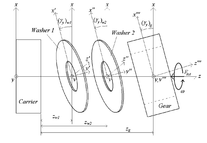 Figure 1. Bearing rendering. (Figure courtesy of Auburn University.)
Types
Figure 1. Bearing rendering. (Figure courtesy of Auburn University.)
Types
There are three basic types of numerical modeling.
1.
Continuum models. This is the most commonly used, but it might only consider certain discrete states of matter or energy such as fluids, solid mechanics and heat transfer. Multiphysics models couple between these fields and are solved using various numerical methods such as finite elements, finite difference and boundary elements. Chemistry is not inherently considered, and this type of modeling can be expensive. It is usually only employed for large scales—small and nanoscale phenomena often are not considered. However, scale-dependent properties can correct this.
2.
Molecular models. These applications are on a much smaller scale and are used for nanoscale solids, fluids and heat transfer. They are inherently multi-physical (most fields are considered). For molecular dynamics, each atom or molecule is considered as a particle governed by defined interaction forces between them. They can require extensive computational resources.
3.
Intermediate models. These are hybrids—a continuum model that is linked to a molecular model—with some sacrifices. Lattice Boltzmann is an example.
In some circumstances, any of these applications can result in the wrong answer. Problems can include:
•
Bad input
•
Invalid boundary conditions or assumptions
•
Multiple solutions
•
Never converges (diverges)
•
Coding errors or bugs
•
Mesh convergence not satisfied.
When using methods such as finite elements, the problem needs to be divided into small parts with enough elements. The number of elements or nodes should be doubled until the error of the desired quantity between cases drops below the desired accuracy.
The tribology factor
The big problem with numerical modeling in tribology is scale. Things on a very small scale affect things on a very large scale. When using numerical methods for investigating problems involving tribological interactions, additional difficulties arise:
•
Thin film lubrication. Most commercial fluid dynamics are not suited for cases that have large dimensions in two directions and micro or nanometer dimensions across the film.
•
Roughness. Factoring in solid surface contact and lubricant flow.
•
Surface chemistry or properties. The effective properties or molecular models.
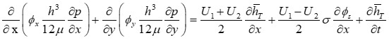
The Reynolds Equation
The Reynolds Equation is used to predict fluid behavior in thin films. It is a simplified fluid dynamics equation that can be solved using finite elements or finite difference methods and is usually used to predict fluid pressure (load-carrying capacity) as a function of geometry and sliding speed. Unfortunately it is not available in most commercial software.
For smooth surfaces with film thicknesses that are large compared to the roughness, the Reynolds Equation can be solved relatively easily. A function predicting the viscosity can be fit to measured data and used to calculate viscosity at each node as a function of shear rate, pressure and temperature.
Molecular dynamics
Molecular dynamics can be used to predict many phenomena, including the impact of additives that minimize the change of fluid viscosity with temperature. This application is able to predict viscosity index additive performance using molecular dynamics modeling (
1). In the future researchers will be able to predict more and reduce testing requirements. Currently all the molecules in a real bearing can’t be modeled since it would be too complicated and expensive.
The molecular dynamics simulation method can be used to explore the possible effect of nanoparticles on thin film lubrication. For example, a similar system of silver nanoparticles in dodecane between iron walls was modeled. The system was sheared until the steady state was reached. The coefficient of friction for different cases was calculated, and the results suggest that nanoparticles affect the thin film lubrication systems and reduce friction (
2).
Surface roughness
Roughness is a big issue in tribological modeling. With a very thin film, the roughness affects the film because the lubricant has to go around the asperities (
see Figure 2). Roughness can be ignored in the full-film regime but must be considered in mixed and boundary lubrication.
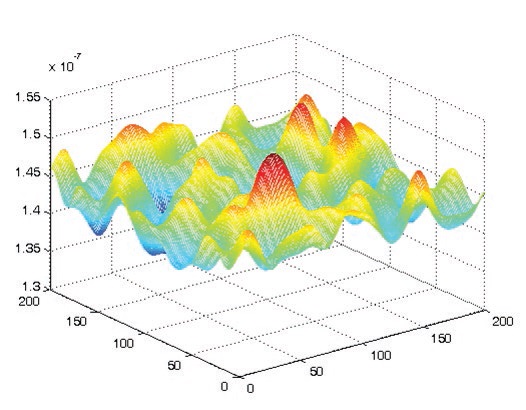 Figure 2. Model showing asperities. (Figure courtesy of Auburn University.)
Deterministically measured roughness and all detail when solving Reynolds Equation can be considered. It can be done, but it is computationally expensive. The Stochastic flow factor (
3) approach adjusts the average flow between the surfaces due to the roughness obstructions.
A modified Reynolds Equation was formulated to include asperity flow effects between two three-dimensional surfaces. These flow effects were taken into account in the form of flow factors, which were incorporated into a modified form of the Reynolds Equation.
The modeling of surface asperities on the microscale is of great interest to those involved in the mechanics of surface contact, friction and wear. When considering the area of contact between real objects, the roughness of their surfaces must be accounted for because it will determine the real area of contact between them. This real area of contact is approximately proportional to the friction. Since surfaces are rough, only the peaks or asperities come into contact. This interaction must be considered when studying the fundamentals of friction, wear and contact resistance.
There are many different scales of roughness and many different methods to model rough surface contact.
•
Hardness model. The contact area is simply the force divided by the hardness (2.8-3 x yield strength).
•
Statistical. The model surface as a statistical distribution of asperities with various heights and properties. It is computationally inexpensive.
•
Deterministic. The real features of the surface are modeled with as much detail as possible. It is computationally expensive and there is no mesh convergence.
•
FFT methods. The problem is solved in frequency domain.
•
Fractal. Multiple scale roughness is considered. However, it assumes that surfaces are self-affine and often oversimplifies the contact mechanics.
•
Multiscale. Considers the multiple scales but without relying on fractal mathematics.
Surface asperities
Most of the previous works on the contact between rough surfaces employed cylindrical or spherical/ellipsoidal shape for the asperities. However, there are some works that employed sinusoidal asperities (
see Figure 3). There is a wide variety of options to consider other effects such as elastic, elastic-perfectly plastic, strain hardening, sliding, adhesion and scale-dependent properties (
4).
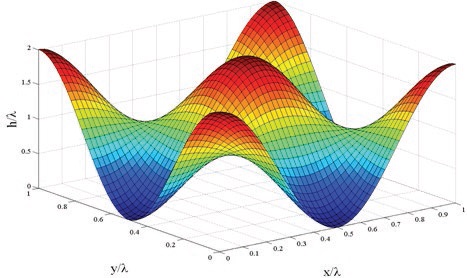 Figure 3. Sinusoidal asperity. (Figure courtesy of Auburn University.)
For scale-dependent mechanical material properties, as the scale becomes smaller and there are fewer features in the contact area, scale-dependent features become relatively larger and the effective hardness (yield strength) of material increases.
Molecular scale modeling
For the molecular scale, continuum-based models appear to work for surprisingly small scales. Scale-dependent properties allow for continuum-based models to be adapted. However, some effects or phenomena seen in molecular scale modeling may be lost in continuum-based modeling. To predict the fundamental surface interactions that cause friction, a model of sliding spherical copper asperities and many other materials has been analyzed many times. Some cases take weeks to run. In order to verify the effectiveness of molecular dynamics simulations, recent works are being made to extend molecular dynamics capabilities into the same range as experiments (
5).
Many rough surface contact models have been implemented, including statistical, fractal and deterministic models. Graphic comparison of models shows that contact area increases with load. For modeling tribological interactions, these models can predict the contact pressure as a function of the surface separation.
Deterministic models can include the actual rough surface geometry and other effects directly into a finite element modeling (FEM) code, although this is not practical. Other models can calculate average pressure as a function of surface separation. The average pressure on a contacting surface can then be calculated in FEM based on the surface separation. Similarly, the electrical and thermal contact resistance can be predicted. Solid friction and wear also can be approximately predicted by assuming they are proportional or related to the contact area.
Coupled solid and fluid problems
Realistic tribological components can be modeled to consider both solid rough surface contact and the effects of fluid dynamics in a mixed lubrication model. FEM can be used to calculate deformations of components due to contact pressures, fluid pressures and thermal expansion (
6). The described methods are coupled through their boundary conditions and so must be satisfied simultaneously. The Newton-Raphson method is often used to solve the non-linear problem.
The viscosity of lubricants depends on pressure. In heavily loaded contacts the pressure-dependent viscosity change can be significant. Under high pressure, lubricants can act as a semi-solid (very thick fluid). This might result in elastic deformation of surfaces in contact. This problem is solved by coupling elastic deformations of the surface to the fluid pressure predicted by Reynolds Equation. This is commonly known as elastohydrodynamic lubrication and is usually solved numerically.
Compressible squeeze film bearing model
Researchers at Auburn University wanted to take a solid surface and vibrate it so that there is no sliding, and lift can actually be generated between the surfaces just by vibrating (
see Auburn University Tribology Minor and Research). They wanted to find out what frequencies and amplitudes were required to levitate the top surface and create a squeeze film effect. The resulting squeeze film bearing model, which included roughness and lubrication, yielded the following results (
see Figure 4):
•
Hydrodynamic lift occurs due to a relative normal motion between two parallel surfaces separated by air (
7).
•
Alternate compression and decompression produces a steady state film pressure.
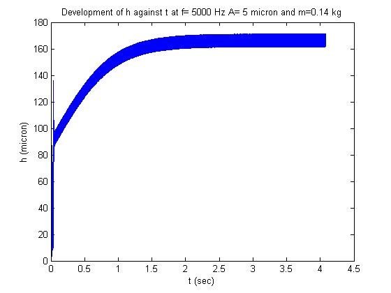 Figure 4. Predicted film thickness of air as vibration causes liftoff and separation between the surfaces. (Figure courtesy of Auburn University.)
Auburn University tribology minor and research
Auburn University offers the first and only undergraduate minor in tribology. An extensive research, master’s and doctorate program is conducted in unison with the minor. The department also is looking for industry partnerships.
•
For general information, contact Dr. Rob Jackson at
jackson@auburn.edu or (334) 844-3340.
•
For information about Auburn University’s tribology minor, click
here.
•
For information on Auburn’s Research Website: click
here.
 Photo courtesy of Auburn University.
Conclusions
Computer-aided modeling capabilities are very strong for general components. The introduction of tribological aspects into a model tends to introduce complications that are often neglected by commercial software. There are some specialized packages out there, but they are hard to find. Care must be taken when using numerical methods as erroneous predictions can result.
Thin film lubrication is effectively modeled using Reynolds Equation and flow factors. It is important to include the effect of micro and nanoscale roughness between the surfaces of much larger components. Although it is still an evolving field, current models are able to make complex predictions of tribological components. Researchers have just scratched the surface.
REFERENCES
1.
Ramasamy, U.S., Lichter, S. and Martini, A. (2016), “Effect of molecular-scale features on the polymer coil size of model viscosity index improvers,”
Tribology Letters,
62 (2), Article number 23.
2.
Ghaednia, H., Babaei, H., Jackson, R.L., Bozack, M.J. and Khodadadi, J.M. (2013), “The effect of nanoparticles on thin film elasto-hydrody¬namic lubrication,”
Applied Physics Letters,
103 (26), 263111.
3.
Patir, N. and Cheng, H.S. (1978), “An average flow model for determining effects of three-dimensional roughness on partial hydrodynamic lubrication,”
ASME J Lubr Technol,
100, pp. 12-17.
4.
The presenter has a review paper on this subject: Ghaednia, H., Wang, X., Saha, S., Xu, Y., Sharma, A. and Jackson, R.L. (2017), “A review of elastic–plastic contact mechanics,”
Applied Mechanics Reviews,
69 (6), 060804.
5.
Liu, X., Ye, Z., Dong, Y., Egberts, P., Carpick, R.W. and Martini, A. (2015), “Dynamics of atomic stick-slip friction examined with atomic force microscopy and atomistic simulations at overlapping speeds,”
Phys. Rev. Lett.,
114, 146102. Read more
here.
6.
This paper has a good example of this: Jackson, R.L. and Green, I. (2008), “The thermoelastic behavior of thrust washer bearings considering mixed lubrication, asperity contact, and thermoviscous effects,”
Tribology Transactions,
51 (1), pp. 19-32.
7.
Mahajan, M., Jackson, R.L. and Flowers, G.T. (2008), “Experimental and analytical investigation of a dynamic gas squeeze film bearing including asperity contact effects,”
Tribology Transactions,
51 (1), pp. 57-67.
Jeanna Van Rensselar heads her own communication/public relations firm, Smart PR Communications, in Naperville, Ill. You can reach her at jeanna@smartprcommunications.com.