Extending wind turbine gearbox life with lubricants
Jean Van Rensselar, Contributing Editor | TLT Feature Article May 2013
On-the-horizon lubricants just might be the best solution to the high loads and extreme conditions that cause early failures.
KEY CONCEPTS
• Wind turbine gearboxes are designed to last for 20 years but are beginning to fail within seven.
• The cause of these failures is mainly extreme internal and external operating conditions.
• New lubricants could potentially reduce the damage and prolong gearbox life.
Philosophers sometimes compare the art of living to a duck—to give the appearance of just floating along, it’s necessary to paddle like crazy underneath. The same could be said for wind turbines and the gearboxes that make them work: inspiring symphonies on the outside, they’re virtual sweatshops on the inside.
They operate almost 24/7 in subzero temperatures, scorching desert heat and high humidity—with saltwater seeping into the tower, and sand buffeting the blades and mechanisms. Add to this the fact that they stop with enough force to destroy the average car transmission several times a day.
The gearboxes, which bear the greatest punishment, are designed to last 20 years but are beginning to fail within seven (1). While the reasons for the early failures are not fully understood, lubricant degradation seems to play a major role.
According to STLE-member Dr. Shuangwen (Shawn) Sheng, senior engineer at the U.S. Department of Energy’s National Renewable Energy Laboratory (NREL), tribological challenges for wind turbines include but are not limited to:
• Complex failure modes involving bearings, gears and lubricants inside wind turbine gearboxes
• Variable and harsh operating conditions:
a. Changing wind speeds and directions
b. Intermittent operation with many starts/stops
c. High transient loads from wind gusts, grid engagement and braking
d. High torque and low-speed input
e. Remote locations that create maintenance difficulty
f. Harsh environmental conditions:
i. Contamination from dust and wear debris
ii. Wide temperature range
iii. High humidity and water ingress
iv. Offshore environments that cause corrosion.
• Diverse operating conditions for grease to meet the necessary requirements from different subsystems: main bearings, generator bearings, pitch bearings, yaw bearings and yaw gears.
• Higher requirements for gear oil than typical industrial applications.
Illustrations courtesy of The University of Akron
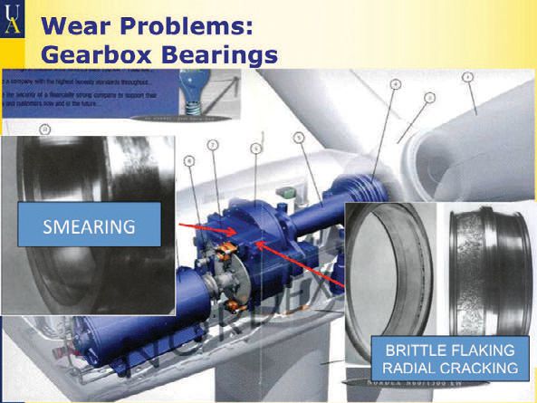
INSIDE THE GEARBOX
The basic components of a wind turbine drive train include the generator, gearbox, disc brake, rotor, hub and input shaft. The gearbox transfers the torque from the slowly rotating input shaft driven by the blades to a high-speed output that drives the generator.
Gearbox failures are one of the most serious breakdowns in a wind turbine because of the high cost of repair/replacement. Replacement costs include the gearbox itself, which represents roughly 10% of the wind turbine’s total cost. Then there’s the expense of getting the replacement gearbox to the site, the crane rental, and the labor costs. Finally there’s the downtime—it usually takes about a week to get a replacement gearbox.
Considering how expensive it is to replace a wind turbine gearbox (between $250,000–$650,000 depending on the turbine size and the location of the wind farm), the premature failure of the gearbox and its lubricants are a primary concern that is getting considerable attention. Depending on the location and size of the wind turbine, just getting a gear out of the machine and onto the ground can cost as much as $75,000.
STLE-member Dr. Aaron Greco, materials engineer at Argonne National Laboratory’s (ANL) Tribology Section in Lemont, Ill., explains, “There has been a deficiency in understanding the load that wind puts on a turbine. There was a need to model the loads, and that is very complex because so many factors come into play. Consider a single wind turbine with a rotor diameter over 100 meters; the wind speed profile across that swept area can be very inconsistent. Now consider a wind plant with several turbines in close proximity, the wake interaction between turbines can complicate even further the load input to the rotor and therefore the drive train.”
STLE Fellow Dr. Ali Erdemir, distinguished fellow at ANL’s Tribology Section, adds, “There are intermittent high stress conditions that are very severe. People in the industry appreciate that, which is why there has been a lot of effort to understand actual operating conditions in order to come up with meaningful solutions.”
Gear failure can occur independently of bearing failure for reasons such as wear from poor lubrication. However, most gearbox failures do not begin as gear failures; they stem from eroding bearings that spew dirt and hardened steel debris into the gear teeth.
“Oftentimes wind turbine gearboxes fail to meet their 20-year design life,” Sheng says. “These premature gearbox failures increase the cost of energy for wind power. Some statistics clearly show that gearboxes cause the largest downtime, although they do not fail as frequently as some of the other subsystems, for example, electrical systems and controls.”
BEARINGS AND LUBRICATION IN OTHER PARTS
What goes on inside a wind turbine? STLE-member Dr. Gary Doll, Timken Professor of Surface Engineering at the University of Akron, describes the key components.
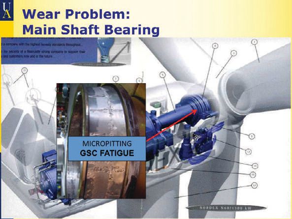
Mainshaft. The most common wind turbine configuration (<2MW) uses two bearings: a spherical roller bearing on the blade side and a cylindrical roller bearing on the generator side.
For 2MW and greater wind turbines, two bearings also are used, but these designs include either two spherical roller bearings, two tapered roller bearings or a double-row tapered roller bearing on the blade side and a cylindrical roller bearing on the generator side. For direct-drive turbines (those without gearboxes), configurations include either two tapered roller bearings, or a double-row tapered roller bearing and a cylindrical roller bearing.
Spherical roller bearings in the mainshaft experience a very high incidence of micropitting, which can lead to bearing failure in as little as two years. Micropitting is caused by highly loaded, sliding contact between the rolling elements and the bearings. A progressive loss of material leads to exceedingly high geometric stresses at points on the ring raceways, which can initiate raceway fatigue.
A spherical roller bearing has two rows, and analysis has shown that the upwind row of these bearings is almost completely unloaded. This means the downwind row carries almost the entire load. The roller/raceway sliding is a consequence of the geometry of a spherical roller bearing.
Solutions to this problem include replacing the spherical roller bearing with preloaded tapered roller bearings or applying a WC/aC:H coating to the rollers of the spherical roller bearing. If the coating is sufficiently durable, the spherical roller bearing will not experience micropitting.
Tapered roller bearings that are used in 2MW and greater wind turbines can experience problems associated with misalignment and lubrication. There is room for significant improvement with the greases used in these bearings.
Generators. Ball bearings are used to support the shafts in generators. These bearings are either all-steel with an electrically insulating coating on the outer rings or a hybrid variety that employs ceramic rolling elements with steel rings.
In the generator, high-frequency currents are induced on the shaft. If not diverted or otherwise insulated, the stray currents that develop in the generator pass through the rolling elements causing extreme local heat and small burnt pits in the bearing surfaces.
Solutions being tried in the field involve electrically isolating the shaft from the housing by either applying a thick, electrically resistant coating like alumina between the outer ring and its housing or using ceramic rolling elements or both. Even with these measures, some turbines still experience electrical damage. Another possible solution is to lubricate these bearings with high dielectric strength oils.
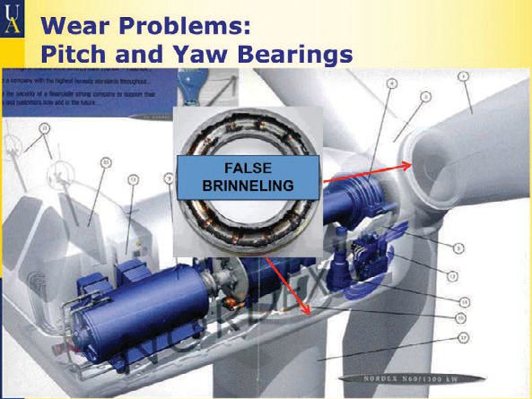
Pitch and yaw systems. Large wind turbines (>250kW) use ball bearings in the pitch and yaw systems. These are typically either 4- or 8-point ball bearings with a gothic arch design.
The tribological issues that limit the reliability of pitch and yaw systems are false brinelling, fretting corrosion and friction. Greases with adequate base oil viscosities and good antiwear additives should be used as the lubricant. The frictional torque of the pitch and yaw bearings is highly dependent on the lubrication as it is required for consistent, low-friction operation. Too much lubrication may cause churning and, therefore, increased bearing torque, and too little increases the metal-to-metal contact of the surfaces and the bearing torque.
GEARBOX ISSUES
Because oils and greases for wind turbine bearings are expected to continuously maintain optimal performance under extreme conditions, they need to meet higher standards than comparable lubricants for other industries. While bearing surface destruction in wind turbines is not much different from that observed in other equipment, the frequency and severity of the destruction is considerably greater.
Blade root bearings, main shaft bearings and yaw bearings are lubricated with grease while the gearbox is lubricated with oil. Even in a well-designed and lubricated gearbox, oil film breakdown can occur during events that overstress components.
There is growing evidence that infrequent but severe torsional reversals may be a major cause of drive train-component problems. Wind turbine drive systems are subject to torsional reversals because the torque in a wind turbine drive train is constantly fluctuating. Bearing load zones can shift more than 120 degrees radially during torsional reversals, applying high loads to skidding rollers and occasionally impact loads large enough to fracture the bearing raceway. Events that can trigger a torsional reversal and damage gearboxes and blades include:
• Emergency stops
• Wind gusts
• High wind shutdowns
• Grid loss and grid faults
• Generator short circuits
• Resonating vibration
• Control malfunctions
• Premature grid engagement.
Torsional reversals can be severe and damaging, although they only occur an average of three times a day. Improved controls have lessened the frequency and magnitude of some events that cause this trauma.
A partial solution is a torque limiter, which provides some protection against forward torque spikes. However, the same torque limit in reverse is high enough to cause damage. A better solution, currently on the market, is a retrofittable torque limiter that has different settings for forward and reverse— the torque limiter can be set at a much lower reverse torque setting than the forward setting (2). Wind turbine gearbox bearing failures typically occur at three critical locations:
1. High-speed locating bearings (most often)
2. Planet bearings
3. Intermediate shaft-locating bearings.
THE ALTERNATIVE: ELIMINATING THE GEARBOX*
Siemens has introduced a 3-megawatt turbine using a direct-drive system. It replaces the conventional high-speed generator with a low-speed generator, eliminating the need for a gearbox.
General Electric is working on something similar for offshore wind turbines. Industry observers say both moves are a direct response to the disappointing performance of gearboxes in the field. But Siemens says that direct-drive also will generate more energy at a lower cost.
Siemens’ new design reduces the weight of the system’s generator. In conventional wind turbines, the gearbox increases the speed of the wind-driven rotor by hundreds of times, which radically reduces the size of the generator required.
Direct-drive generators operate at the same speed as the turbine’s blades and must therefore be much bigger than conventional generators. At the same time, the Siemens turbine weighs two tons less than a less powerful gearbox equipped with a 2.3-megawatt turbine.
Much of the weight reduction comes from the use of permanent magnets in the generator’s rotor–a technology that GE also is using. Conventional turbine generators use electromagnets (copper coils fed with electricity from the generator itself). A much smaller array of permanent magnets can generate the same magnetic field as copper coils.
Siemens further reduced the weight by inverting the generator’s design. While the GE design includes a steel rotor covered with permanent magnets spinning inside a stationary shell, the Siemens rotor is a steel cylinder, with permanent magnets on the inside that spins around a stationary column.
*From here.
LUBRICATION-RELATED BEARING FAILURES
Erdemir explains, “Lubricants are supposed to reduce the susceptibility to failures, but if they become highly contaminated (for example if they accumulate dust, dirt, water, salt, etc.), they will progressively lose their effectiveness. Designers do a lot of engineering to make sure that the stress does not exceed the yield strength of base materials from which the components are made. Even though they design to make sure that the surface can withstand the stress, sometimes the deformation or crack occurs beneath the surface, which is very difficult to correct.”
Even if a bearing is designed and manufactured for a specific application, premature damage and wear may occur because of contamination, misuse, starved lubrication or all three. Two failure modes that may be attributed to lubrication issues are white structure flaking and axial cracks.
White structure flaking. This phenomenon is induced when hydrogen diffuses into the bearing’s steel. The white structures are caused by localized, microstructural changes and indicate that localized plastic deformation is present in rolling contact fatigue. The type of lubricant, bearing material and the presence of static electricity influence white structure flaking.
Axial cracks. The inner rings of high-speed and intermediate shaft locating bearings sometimes exhibit axial raceway cracks. Axial cracks extend from the raceway surface to about halfway through the inner ring of the bearing.
Sheng explains, “For gearbox bearings, the top two failure modes appear to be scuffing and axial cracks. Axial cracks occurring in high-speed shaft bearing inner raceways appears dominant and recently has attracted a lot of R&D attention. There is still no consensus on the root causes and possible mitigation methods for this failure mode.”
Right now Greco is working with the U.S. Department of Energy to uncover root causes for cracks in bearings. “The state of the stress beneath the contact surface plays a role,” he says. “It can be related to lubrication, but it is very complex. What may start as a small crack will propagate over time and lead to failure. We are trying to understand the cause of that failure. It can be the material itself, the surface finishing or the lubricants. We are collecting failed bearings from the field and sectioning the bearings so that we can examine cross sections.”
He adds, “The industry has been very receptive to working with us. It’s such an important issue that we’ve been able to form a collaborative with those who have a vested interest such as manufacturers, plant operators and lubricant manufacturers.”
THE FIVE DOMINANT SURFACE DAMAGE MODES
At the 2011 Wind Turbine Tribology Seminar sponsored by National Renewal Energy Laboratory, Argonne National Laboratory and the U.S Department of Energy experts identified the following five predominant surface damage modes:
1. False Brinelling and Fretting. This is a common issue for blade pitch and yaw bearings and gear components, which experience little structural vibration. Lubricants are squeezed out of the contact area and protective oxide layers dissipate. The result is accelerated wear that forms indentations in the raceway and impedes the smooth operation of the positioning system. These issues can be addressed through redesign and the use of coatings and lubricants with proper antiwear additives.
2. Micropitting. In bearings, it is typically caused by sliding or skidding during unsteady operation. Micropitting is commonly a precursor to larger surface failures. In general, the major factors influencing micropitting include inadequate EHL film thickness, surface roughness, unsteady operating conditions and antiwear lubricant additives.
3. Scuffing. This is surface damage caused by sliding contact friction caused by inadequate lubrication. It is generally attributed to a lubrication deficiency, caused by inadequate design, lubricant supply and additive formulation. The introduction of EP lubricant additives or surface coatings usually solves the problem.
4. Electric Discharge. This occurs when factors such as faulty insulation or improper grounding allow electric current to pass through the bearing and damage the surface. Electric current might originate in components or it can result from the accumulation of static charge and discharge. Electric discharge damage can be prevented with proper electrical insulation and grounding and by following proper welding procedures.
5. Microstructural Alteration. This includes white etching area (WEA) cracks and can lead to axial cracking and macropitting early in relatively new bearings. This is one of the more critical and least understood wind turbine failure modes. While not unique to the wind industry, it is found to be much more prevalent than in other applications. As reported, there are several theories about the cause of WEA cracks, including lubricant decomposition.
EXISTING LUBRICATION SOLUTIONS
Unlike scheduled wind turbine maintenance costs that are relatively low, unscheduled maintenance costs can be exorbitant. Because most wind farms are fewer than five years old and most warranties only cover the first 2-5 years of the wind turbine’s life, manufacturers have been bearing the burden of unscheduled maintenance and repair. But as wind farms start to go out of warranty, this is rapidly changing; the onus for maintenance and repair is shifting to owners.
The minimum requirements for a good wind turbine gear oil include:
• Long oil life: minimum 3-5 years
• Inclusion of antiscuff/extreme pressure additives with a high load-carrying capacity
• Wear performance that remains constant as the oil ages
• Micropitting protection
• Oil cleanliness: 16/14/11 for new oil 18/16/13 for used
• Cold start-up protection
• High operating temperatures
• Oxidative stability
• Resistance to sludge formation
• Does not affect the filter service interval
• Rust and corrosion protection.
A good wind turbine oil would have the thermal stability of high quality hydraulic oil and the extreme pressure properties of gear oils, along with additives that prevent micropitting. Additional requirements by gearbox and wind turbine manufacturers include:
• Compatibility with elastomers and paints
• Can pass static and dynamic tests
• Can pass long-term tests (at least 1,000 hrs)
• Can pass foam tests
• Can pass micropitting tests
• Can pass bearing antifriction tests (3).
STLE-member Dr. Gary Doll, Timken Professor of Surface Engineering at the University of Akron in Akron, Ohio, points out that neither white structure flaking nor radial cracking have been reported to occur in casecarburized bearings containing about 20% retained austenite. This important fact argues against hypotheses that attribute these types of bearing problems solely to hydrogen from water or oil in the lubricant. White structure flaking and scuffing appear to be different manifestations of the same mechanism: specifically tribologically induced damage arising from high to very high cyclic shear stresses from transient loads applied to rollers that are sliding against the raceways.
A solution that is now incorporated in new gearbox designs to avoid the scuffing and white structure flaking problems is preloaded tapered roller bearings instead of cylindrical roller bearings in positions where problems have been numerous. Unlike cylindrical roller bearings, the rollers of preloaded tapered roller bearings experience much less roller/raceway sliding when the rollers are outside of the load zone. So when rapid transients occur (such as those arising from generator/ grid engagements) that deflect the high-speed and intermediate high-speed shafts and rapidly alter the load zone of the bearing, tapered roller bearing raceways experience much less shear stress than their cylindrical roller bearing counterparts.
Doll argues that the impact loads from rapid torque reversals are the main contributors to radial cracking, the generation of irregular white etch areas (IrWEA) and scuffing. If that is the case, scuffing from roller skidding will be reduced by using the preloaded tapered roller bearings instead of cylindrical roller bearings in the locating shaft positions. Furthermore, if the microstructures of these bearings contain about 20% retained austenite (as the gears do) the risk of generating IrWEA and radial cracking from high impact forces arising from torque reversals will be reduced or eliminated (4).
ON THE HORIZON
Currently, the NREL Gearbox Reliability Collaborative (GRC) is exploring the wind turbine drive train system in order to account for load conditions that lead to overstressed contacting elements. In addition to collecting information on field failures, the GRC is employing field trials, advanced computer simulations and dynamometer testing.
ANL is developing advanced surface treatments and lubricant additives that can benefit the wind industry using distinctive bench-top testing capabilities and lab-based coating and lubricant fabrication equipment.
Oak Ridge National Laboratory (ORNL) also has exclusive tribology and metallurgy capabilities. The lab has been engaged in forensic analysis of damaged wind turbine bearings using advanced microscopy.
NANO-LUBRICANTS
Nanoparticle-based lubricant additives have been under development for several years to produce performance comparable to traditional additive packages. Nanoparticle additives, (usually boron or carbon) are engineered to interact with the contacting surface to produce a low friction/protective boundary film. Results indicate friction reduction and evidence of the tribofilm. Micropitting protection significantly improves—tests showed that micropitting was nearly eliminated.
ISOTROPIC SUPER-FINISHING
Isotropic super-finishing modifies the bearing surface and can eliminate micropitting. It can increase both lubricant life and cleanliness. Important for gearboxes—it also increases component life. It involves eliminating directionally oriented grinding asperity rows and can significantly reduce roughness without compromising the component’s shape.
DLC COATING
Lubricant-derived DLC is a new type of boundary film that results from a reaction with base oil molecules to form a slick and protective boundary layer. It can generate boundary films from oils that do not contain bearing-damaging organo-metallic additives, which may cause early failure in some gearboxes.
ULTRA-FAST BORIDING
Ultra-fast boriding enhances the hardness of gear and bearing surfaces by more than 200% over standard carburizing (5). This is achieved through an advanced electrochemical process that is significantly faster than standard boriding, making it economically practical for wind applications. Research shows the sliding wear performance of the borided surface is comparable to standard carburized gear steels. Erdemir, who has taken the lead in this research, says that compared to carburizing, ultra-fast boriding will be significantly less expensive.
Erdemir explains, “This is a process that we have actually scaled up here (at ANL), starting from scratch. It’s been very effective in turning the surface of steel into a very hard boride layer. With ultra-fast boriding, the surface will still wear, but it will wear at least 10-20 times more slowly than what is currently being used. It’s a very fast, very efficient process that has some unique possibilities. The initial phase of the project demonstrated that we actually can treat gear steels. In the second phase, we are looking at practicalities such as applications.”
Erdemir adds, “In wind turbines, roller bearings could benefit from ultrafast boriding. But the gears, depending on the size or type, might actually present a challenge. An option is to combine boriding with nanolubrication.”
The technology has been licensed to Bodycote, which could (upon interest) start producing ultra-fast borided wind turbine parts this spring.
There is growing evidence that infrequent but severe torsional reversals are a major cause of drive train-component problems.
www.canstockphoto.com
EXTENDING SERVICE LIFE
Tower climbing is a necessary but precarious wind farm maintenance and repair activity—equivalent to scaling a 20-story building. The logistics of servicing offshore turbines are especially daunting (6).
Wind turbine maintenance is scheduled biannually. Each time the turbine is down for 12-18 hours, with maintenance staggered so only a few turbines are down at one time. Generally, the only time activity at the entire wind farm comes to a halt is during substation maintenance twice a year (about 12 hours each time).
Oil drain intervals for wind turbine gearboxes are typically between eight and 12 months, with one major manufacturer extending its interval to 16 months following a thorough field evaluation. The goal for the next generation of offshore oils is a drain interval of three years.
Due to enhanced properties of newer fluids used in specialty lube for life applications (and potentially in gearboxes), the need for condition monitoring and/or maintenance of the gearbox could be reduced significantly and has the potential to be eliminated.
The superior viscosity temperature performance of lube for life oils is lower than that of the oil currently used in gearboxes and results in friction reduction and reduced wear of the internal gears and components. Full-scale wind turbine gearbox trial results using these oils indicate a bonus of improved power output efficiency.
As wind farms age, the number of failing turbines is growing at an alarming rate. Although part of the problem is poor maintenance and poor lubricant selection, bearings in gearboxes fail early, even when systems are well-maintained and optimal lubricants are used.
The main cause of the early failure of wind turbine gearboxes appears to be high load under extreme conditions and not the lubricants themselves. Therefore, advanced lubricants may be a good solution for extending the life of gearboxes that are already in place.7 Assuming that eventually design changes in new gearboxes reduce the stress, advanced lubricants will still play an important role in providing an extra measure of protection and prolonging life.
“Wind turbines are a very, very important technology that hold a lot of promise,” Erdemir concludes. “There are some technological challenges such as engineering the surfaces and the lubricants, but I think we are clever enough to overcome those challenges. Personally I feel like the problems can be solved if we all do our homework.”
REFERENCES
1. From here.
2. From here.
3. 2011 Wind Turbine Tribology Seminar-A Recap Sponsored by NREL, Argonne National Laboratory (NRL), Leather, John; (available here)
4. Ibid: 2011 Wind Turbine Tribology Seminar: click here.
5. Carburizing is a surface-hardening process that involves diffusing carbon into a low carbon steel alloy such as chrome or nickel in order to form a high carbon steel surface.
6. To see a video of a maintenance worker climbing the inside of a wind turbine tower, visit here.
7. Successful aerospace applications are an inspiration for overcoming tribological challenges in wind turbines. For example, rolling element bearings in the aerospace industry generally have much longer lives, 10 years or more, even though they are subjected to higher loads than wind turbines.
8. From here.

Jean Van Rensselar heads her own communications firm, Smart PR Communications, in Naperville, Ill. You can reach her at jean@smartprcommunications.com.