MWF heat treatment: Options for a critical process
Dr. Neil Canter, Contributing Editor | TLT Feature Article March 2010
How end-users have a variety of options for annealing and hardening metal alloys
KEY CONCEPTS
•
Heat treatment is a metalworking operation used to adjust the physical or mechanical properties of metals.
•
There are many options that can be used to heat treat metals, including oils, polymers, salts, gases and a process known as intensive quenching.
•
While heat treatment remains an important manufacturing technology, it must become the most cost-effective technology to remain viable in the 21st Century.
When the topic of metalworking is raised, most of us think of drilling a hole in a piece of metal or bending a metal part to form a component for an automobile. Not as many individuals realize that another process included under the realm of metalworking is heat treating or quenching.
Heat treatment is utilized to adjust the physical and mechanical properties of metals so that they can be used in subsequent metalworking applications. These properties are changed by the controlled heating and then cooling of metals. In many cases, the objective of heat treatment is to increase the strength of a specific metal alloy. Most operations are conducted on steel alloys, but nonferrous metals such as aluminum and titanium also can be heat treated.
Daniel H. Herring, president of The Herring Group Inc. in Elmhurst, Ill., says, “The two main processes in heat treatment are annealing and hardening. In the case of annealing, the microstructure of the metal is softened to restore its ductility, increase toughness, adjust grain size and remove residual stresses. Hardening of ferrous alloys in particular is accomplished to increase the strength and wear properties of the metals involved.”
For ferrous alloys, the objective is to increase the temperature above the upper critical temperature (Ac
3), which is dependent on the composition of the alloy in question so that the metal is completely in the austenite phase. The alloy is then rapidly cooled by exposure to either a quenching fluid or gas so that it can be converted into the harder martensite phase. Final hardness is dependent upon the carbon content of the steel. For example, martensite has a hardness of 30 HRC (0.10%C steel) to 55 HRC (0.40%C steel) to 65+ HRC (0. 80%C–1.25% C steel).
A sufficiently fast cooling rate is needed to minimize the formation of bainite and pearlite phases which are softer than martensite and, in some instances, will negatively impact the physical properties of the steel. Bainite has a hardness of 28–48 HRC (0.40%C steel) to 40–58 HRC (0.80%C steel) and pearlite has a hardness of 80–90 HRC (0.40%C steel) to 30–40 HRC (0.80%C steel).
A continuous cooling curve showing the cooling rate of a ferrous alloy is shown in Figure 1. Conversion to martensite starts at the Ms temperature while the complete transformation to this phase is shown at the Mf temperature.
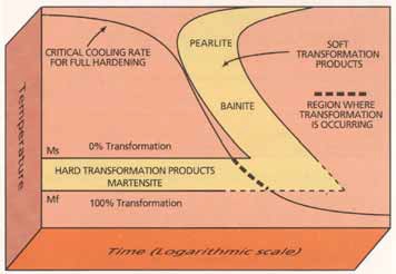 Figure 1. The cooling curve for a ferrous alloy shows the conversion from the austenite phase to the martensite phase, which starts at the Ms temperature and is completed at the Mf temperature. (Courtesy of Houghton International, Inc.)
The key to accomplishing this process is the uniform removal of heat from the surface of the metal part in question. Herring says, “The speed of heat treatment is considered by some the most important aspect, but speed alone is not the total answer. If no other factors are considered, a rapid heat-treatment process alone will lead to distortion of the metal.”
Herring also points out that added metal distortion can increase the number of post-operations which need to be done on the heat-treated metal. He adds, “Post heat treatment grinding of gears can be a big expense.”
Quenching of ferrous alloys occurs in three stages: the vapor blanketing stage (Stage A), the nucleate boiling state (Stage B) and the convection stage (Stage C). Stage A involves the hot surface of the metal meeting the quenchant. In most cases, the quenchant is a liquid which results in the generation of vapor surrounding the metal part. Heat transfer is very low at this stage and occurs mainly through radiation from the vapor. Figure 2 shows how large a vapor blanket can form when a piece of hot steel is immersed in water.
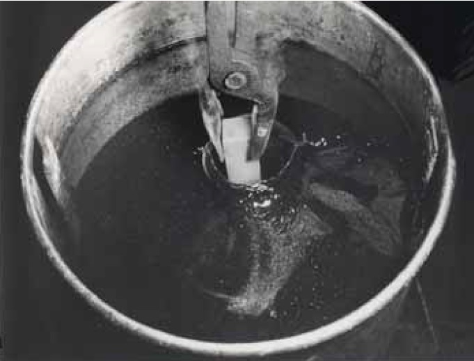 Figure 2. Immersion of a hot piece of steel in water can generate a large vapor blanket in Stage A of the quenching process. (Courtesy of G.E. Totten & Associates, LLC)
Stage B is characterized by the formation of boiling in the quenchant in close proximity to the metal surface. At this point, heat is rapidly moving away and the temperature of the metal part drops rapidly to a point below the boiling point of the quenchant.
With this cooling, the metal part moves to Stage C in which cooling occurs mainly by convection. The rate of cooling is dictated by the quenchant’s specific heat and thermal conductivity. For the most part, heat removal is quite slow at this stage of quenching.
The transition from Stage A to Stage B is shown in the quenching of a cylindrical chromium, nickel steel alloy in oil at a temperature of 60 C (140 F), as shown in Figure 3. In the time frame between 4.3 seconds and 12.3 seconds after the start of quenching, an interface between the vapor phase and nucleate boiling slowly rises to the top of the sample.
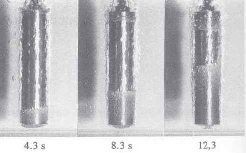 Figure 3. The transition from Stage A to Stage B in the quenching of a piece of a chromium-nickel steel alloy shows the interface between the vapor phase and nucleate boiling slowly rising to the top of the sample. (Courtesy of G.E. Totten & Associates, LLC)
Gajen Dubal, heat treating specialist for Heat Bath, Inc., in Detroit, says, “The ideal quenchant should have no vapor phase, fast nucleate boiling and a slow convection stage.”
Herring adds, “If the nucleate boiling stage can be controlled, then distortion of the metal is minimized.”
QUENCHING OPTIONS
The main quenchants used are oils and polymers. Oils have been utilized since the latter part of the 19th Century and are the most popular quenchant today. Polymers use has become significant, particularly during the past 40 years.
But there are other options that can be used including molten salts and gases. A very recent technique known as intensive quenching was developed 35 years ago and works with either pure water or low concentration salt/water solutions.
Advantages and disadvantages of each of these techniques are described in the following paragraphs.
QUENCHING OILS
Dr. Scott MacKenzie, technical service laboratory manager for Houghton International in Valley Forge, Pa., indicates that oils are used for most heat-treating applications. He says, “Oil viscosity can range from approximately 50 SUS to in excess of 2,500 SUS (at 100 F). Oil selection depends on the application, the type of steel heat treated and the quenching temperature. For low temperatures [less than 100 C (212 F) ], oils with viscosities of less than 150 SUS are used. Higher viscosity oils are used at temperatures above 100 C (212 F) because of the need to have a higher flash point and greater thermal stability.”
Cold temperature oils are used in applications where distortion of the metal is not a major factor. For higher temperature applications up to 200 C (392 F), hot quenching oils are needed to ensure that distortion is minimized. This process is known as marquenching.
Complementing the base oil are additive packages that improve quenching speed and contain antioxidants. The former is known as speed improvers. MacKenzie says, “Speed improvers increase the wettability of the oil during the quenching process. Typical additive classes used are alkali sulfonates and complex organic polymers. Other additives are used to boost the thermal stability of the base oil.” Further information on the composition of oil quenchants can be found in a recent article (
1).
If the proper packages are selected, low-temperature quenching oils will not require any further additions of additives while in use, according to MacKenzie. In contrast, additive depletions in hot quenching oils due to temperature and drag-out means that tankside addition of packages maybe required to maintain performance. However, it depends on the quality and type of additive package, as well as the application.
MacKenzie believes that oils are generally robust and simple to use. But he maintains that they are expensive and may be difficult to dispose of readily.
Dubal is mainly concerned about the safety and environmental issue in oil quenching. He says, “In a safe quenching process, the operating temperature of the oil should be 55 C to 83 C (130 F to 180 F) below its flash point.” Figure 4 shows the concern with fire that can occur when oil temperature exceeds the flash point and the fire point.
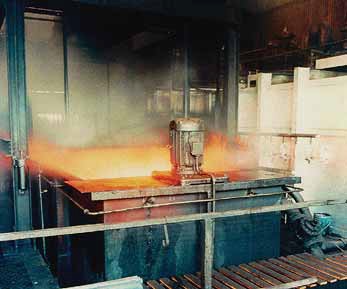 Figure 4. Fire is a major concern in working with quenching oils. Operating temperatures in quenching should be 55 C to 83 C (130 F to 180 F) below the oil’s flash point. (Courtesy of Houghton International, Inc.)
POLYMER QUENCHANTS
Figure 4. Fire is a major concern in working with quenching oils. Operating temperatures in quenching should be 55 C to 83 C (130 F to 180 F) below the oil’s flash point. (Courtesy of Houghton International, Inc.)
POLYMER QUENCHANTS
The main type of polymer quenchant used is based on polyalkylene glycols (PAGs) (
2). These quenchants are aqueous solutions of PAGs formulated with corrosion inhibitors and biocides.
The performance of polymer quenchants is influenced by their ability to become water insoluble at elevated temperatures. This behavior is known as inverse solubility. When hot metal is introduced into the polymer quenchant, a film of the liquid polymer will deposit on the metal and facilitate heat transfer.
Performance factors that must be considered include the concentration of the polymer, agitation rates and quenchant solution temperature. MacKenzie says, “Polymer quenchants are generally cheaper than oil on a per gallon basis once they are diluted, but more attention must be paid to concentration control, cleanliness, microbes (bacteria and fungus) and the application.”
Dubal indicates that polyvinyl pyrrolidones (PVPs) also can be used as a basestock for polymer quenchants. In some cases, PVPs are considered to be an upgrade on PAGS.
Dubal cautions that bacterial growth can be a problem in using some polymer quenchants. He says, “If a polymer quenchant is only occasionally used and sits idle for a long time without agitation, then bacterial growth can be an issue, and biocides need to be added to control potential problems.”
SALTS
Molten salts have been used for more than 60 years as quenchants. Dubal says, “The key is to keep the temperature above the melting point of the salt. Operating temperatures for molten salts range from 150 C to 590 C (300 F to 1100 F) depending upon the composition of the salt.”
Most of the salts utilized in quenching are nitrate-based with some prepared from chloride (
3). The nitrate-based salts are binary or tertiary mixtures of sodium and potassium nitrate and nitrite.
In contrast to oils and polymers, salts quench by a different mechanism. Stage A (vapor blanketing stage) and Stage B (nucleate boiling) of quenching do not occur with salts. The quenching process moves directly into Stage C (convective cooling), and most of the heat is removed during this stage. This results in a more uniform heat removal with minimal distortion of the part.
With the contact between salt and metal, there is an expectation that corrosion could be a problem. Dubal says, “Not much corrosion is seen with molten salts. In most cases, ordinary carbon steel can be used to contain the salt bath. Corrosion inhibitors are used in follow-up operations because the quenched parts are washed down with water.”
GASES
High-pressure gas quenching is the method of choice in heat treatment in vacuum furnaces using inert gas or blends thereof. Bill Gornicki, vice president of sales for ALD-Holcroft in Wixom, Mich., says, “The pressure of the gas can range from 2 bar to in excess of 20 bar. It can be varied to adjust quench intensity, which enables some degree of control to be exerted over part distortion.”
The only phase of quenching that the parts go through when gas is used is convection. Gornicki says, “In gas quenching, the vast majority of systems in North America impinge the quenching gas in a 360-degree nozzle pattern aimed directly at the workload. The gas then exits the hot zone, cycles through a water-cooled heat exchanger and is once again cycled through the workload.”
Gornicki continues, “In the European market, the vast majority of systems use directionally controlled gas flow (top/down, bottom/up, side-to-side). The direction of the gas flow can be altered during the quench sequence. These capabilities offer some additional control on quench intensity, thereby offering more distortion control on the workload.”
Nitrogen, argon and helium are the most common gases used in commercial heat-treating applications. Dr. Minfa Lin, senior principal materials engineer for Air Products in Allentown, Pa., says, “Gas blends of helium and argon provide better cooling at a lower cost as compared to 100% helium. We found that an ideal gas mixture is 85% helium and 15% argon (
4). A typical temperature for metal being quenched is 1150 C (2100 F) and a typical gas pressure used is 8 bar.”
Gas quenching has several advantages over the use of oils, polymers and salts. Gornicki says, “Metal parts emerge from the process bright and clean, which means there is no need for post-quench washing. Intergranular oxidation of the metal is eliminated if the process is done in a vacuum furnace.”
Lin believes that quenching with gas provides much more uniform cooling while keeping the part clean compared with conventional methods such as oil. He adds, “The reason for more uniform cooling by gas is that the cooling occurs through convection only. In contrast, the four different modes of cooling by liquid quenchants may produce larger temperature differences and distortion in the part if not properly controlled.”
Gornicki is in agreement and says, “With gas quenching, there is a greater capability to control distortional characteristics of the part, thereby minimizing/eliminating post heat-treat machining and/or straightening operations.”
But gas is not as effective in facilitating heat transfer as compared to liquid quenchants. Lin says, “Gas cooling cannot be used universally. Its use depends on composition (hardenability), size, microstructure, cleanliness and uniformity requirements of the part being quenched.”
Gornicki adds, “Materials to be quenched with gas must have higher alloy content. Gas cannot quench low-alloyed metals effectively.”
INTENSIVE QUENCHING
Intensive water quenching cools down metal at a much more rapid rate than other approaches (
5). Highly agitated water is used during the quenching procedure to quickly and uniformly remove heat from the metal part. During conventional oil quenching, parts usually develop high tensile stresses on the surface that result in part distortion or even cracking. Intensive quenching takes advantage of the fact that high “current” (while quenching) and residual compressive stresses are formed on the part surface. These beneficial compressive stresses eliminate part distortion and part crack formation. An additional benefit of intensive cooling is the mechanical property improvements such as strength, wear resistance and fatigued life.
Joseph Powell, president of IQ Technologies Inc. in Akron, Ohio, says, “During rapid and uniform cooling of steel parts, we have found that the austenite steel on the surface quickly becomes uniformly martensite. Since the specific volume of the martensite is greater than the specific volume of austenite, the faster the part shell is transformed to martensitic, the higher the compressive stresses that can be formed. These compressive stresses act like a die holding the part together—both during the quench and as the part is in service. The core of the metal part cools from the austenite phase by rapid conduction through the cold shell, which properly toughens the part core.”
The vapor-blanketing stage of quenching is non-uniform and is therefore eliminated in intensive quenching. Powell says, “The rapid cooling of the metal part moves quenching to the nucleate boiling phase or to direct convection cooling. Once the outer martensite shell is developed, the intensive quenching process is interrupted and the part is moved into the air to cool the core by rapid conduction until the temperature equalizes throughout the part.”
This phenomenon is shown in Figure 5 as the difference between intensive quenching and oil quenching for 1045 alloy steel are depicted. The important aspect is that after 10 seconds in intensive quenching (unlike in oil quenching), the shell is formed when the part core is extremely hot and more space is available for the core to expand as it cools.
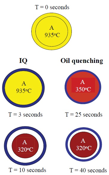 Figure 5. Intensive quenching differs from quenching with oils in that the martensite phase forms more quickly and an outer shell is produced that enables the inner core to expand as it cools. (Courtesy of IQ Technologies, Inc.)
Powell indicates that intensive quenching of a specific steel alloy leads to improved physical properties as compared to quenching with oil. He projects that the strength of a quenched ferrous alloy can increase about 20% and at the same time ductility is increased by up to three times that of oil quenched parts. In addition, the improved material properties combined with higher compressive stresses can extend part service life from 30% to 800%. A 6,000-gallon intensive quenching system is shown in Figure 6.
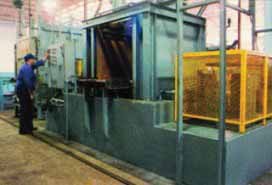 Figure 6. Intensive quenching can be done in the 6,000-gallon system shown. (Courtesy of IQ Technologies, Inc.)
DISTORTION VS. SPEED
Figure 6. Intensive quenching can be done in the 6,000-gallon system shown. (Courtesy of IQ Technologies, Inc.)
DISTORTION VS. SPEED
There are a lot of quenchant types to choose from and two factors that must be assessed are distortion and the rate of heat transfer. Herring points out that these two parameters work against each other. A technique that provides minimal distortion also does not generate a high rate of heat transfer and vice versa.
The list of quenching options and how they rate from both a distortion and heat transfer perspective are shown in Table 1. Air provides the lowest degree of distortion but also is very poor from a heat-transfer perspective. In contrast, brine or caustic provide good heat transfer but poor distortion.
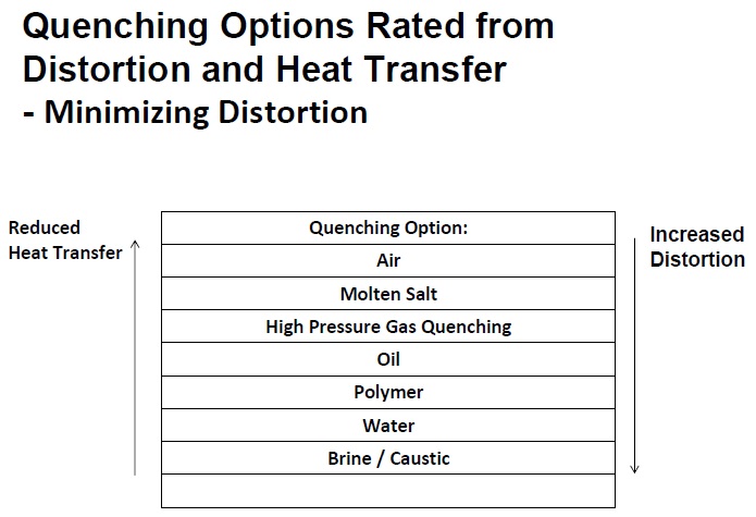 Table 1. Rapid heat transfer and minimal distortion are two parameters ideal for a quenchant. Unfortunately, this table shows that these two characteristics work against each other. Selection of the proper quenchant option should be made after analysis of the parameters involved in the operation. (Courtesy of The Herring Group, Inc.)
Herring comments, “Heat treatment is comparable to a teeter totter where the user must weigh many parameters. Give and take is required to find the right combination of parameters and balance them.”
SELECTION CRITERIA
Prior to heat treating a specific metal alloy, the quenching formulator and end-user must do their homework to determine how the metallurgy of a specific alloy will respond to the quenching process. Dubal says, “
ASM Handbook Volume 4 on Heat Treating is a valuable reference (
6). For a specific steel or alloy, the two-volume
Heat Treater’s Guide should be consulted (
7, 8). Time-temperature-transformation and continuous cooling transformation diagrams can be obtained from
Atlas of Time-Temperature Diagrams for Iron and Steels (
9).”
MacKenzie indicates that there are differences in quenching ferrous alloys as opposed to nonferrous alloys. For a ferrous alloy, the physical dimension of the specific part and its mechanical properties must be known. He says, “The steel alloy, its hardenability, cross-section thickness and distortion are primary variables that must be considered, regardless of whether the quenchant is an oil or a polymer. The type of equipment also must be considered. As a general rule, the mechanical properties (hardness and tensile properties) and the propensity to residual stresses and distortion are the primary things to consider.”
Two other criteria that are important for steel are elongation and fracture toughness, particularly in applications such as a landing gear.
Further details on the heat treatment of ferrous alloys is found in a recent review (
10).
MacKenzie points out that nonferrous metals such as aluminum, some titanium alloys and beryllium-copper alloys are quenched with water or diluted polymers. He adds, “For some alloys (especially beryllium-copper) a very fast quench is required, and only water is allowed to be used.”
Herring indicates that hardening of nonferrous alloys occurs through a diffusion-related hardening mechanism as compared to the phase transformation (austenite → martensite) seen with ferrous alloys. He says, “Nonferrous alloys are hardened in a two-step process starting with solution heat treating and quenching followed by age or precipitate hardening.”
In solution heat treating, the metal part in question is placed in a saturated solution of the hardening elements that need to be incorporated into the alloy. Soaking of the metal part is conducted at a sufficiently high temperature to add these elements. Rapid quenching is then accomplished to ensure that the needed hardening components do not precipitate out of solution. As a result, a supersaturated solution is retained at room temperature.
Age hardening of wrought aluminum and copper alloys usually takes four to five days at room temperature. Precipitation hardening also can be conducted at temperatures above ambient, for example between 115 C and 200 C (240 F to 390 F) for 5-48 hours. Herring says, “In precipitation heat treatment, a precipitate or second phase forms on the grain boundaries of the metal alloy. This leads to a change in the internal structure of the metal.”
In gas quenching, a similar process is carried out to select the proper operating conditions. Gornicki says, “Among the criteria to be evaluated are the metal alloy, largest cross section of the specific material to be quenched, load size/ production throughput requirements and desired results. He indicates that experimentation and cycle development are usually done to ensure that the desired results are obtained.
Lin says, “Helium and argon are both inert and can be used with both ferrous and nonferrous metals. Selection of the gas is based on the final microstructure and the required cooling rate for the metal. For example, in solution annealing of aluminum alloys, parts will need to be quenched very fast to prevent second phase precipitation, and gas cooling may not be suitable for this process due to its limited cooling capacity. In the case of annealing pure titanium grades, it does not require extremely fast cooling, so helium can be used.”
Higher gas pressures and faster gas flow speeds are needed for hardening ferrous alloys that require a faster cooling rate. Lin indicates that the gas pressure used in these applications is typically 20 bar with gas flow speeds in the range of 30 m/sec.
While suited for ferrous alloys, intensive quenching also can be used to solution anneal aluminum and titanium alloys. Powell says, “We have found that the intensive quenching system can be used to solution treat aluminum in a more uniform manner than other techniques and without the need for polymer quenchants. The high cooling rate also provides a corrosion benefit to the aluminum.” One application cited by Powell for this process is the preparation of aluminum shovel handles for the U.S. Army. A similar benefit was found in the preparation of titanium pucks for subsequent forming operations.
CONTAMINANTS
In a similar manner to other types of metalworking fluids, contamination of quenching fluids can lead to performance problems and safety issues, particularly in the case of oils (
11). Herring says, “Contaminants can cause great difficulties with quenching depending upon the process. For example, in case hardening steel, carbon is introduced in a process known as carburization. This will lead to the creation of free carbon (soot) that will find its way into the quench oil. Over a longer term, buildup of soot will change the heat transfer properties of the quenching oil and also accelerate oxidation of the oil.” Soot is also a very fine particulate and very difficult to filter.
Water is a contaminant that can increase the possibility of a quench oil fire. Herring remembers, “A maintenance man who knew better poured half a cup of cold coffee into an 1,800-gallon integral quench oil tank several times over the three- to five-day shutdown period. The result was a quench oil fire when the unit was returned to service.”
Dubal feels that hydraulic fluid contamination can create problems. He says, “If the hydraulic fluid is an oil type, its leakage will alter the quenching performance of oil. But if the hydraulic fluid is a water-based polymer, the result could be disastrous. It may cause non-uniform quenching and fast heat removal in Stage C, leading to excessive distortion and, in extreme cases, cracking. It also poses a serious fire risk. So no amount of water-based hydraulic fluid or water in oil is considered acceptable. In comparison, polymer quenchants can tolerate up to 1% hydraulic fluid of both types.
The presence of hydraulic fluid of any type in molten salt can become a major safety concern and can lead to fire or explosion. This concern can be overcome by installing pneumatic systems in place of hydraulics.
Herring indicates since heat treatment affects the internal structure of a material—at a level undetectable to the naked eye—that the introduction of any unforeseen variables or contaminants can lead to problems. He says, “Equipment and process variables must be controlled very carefully to ensure that the microstructure of the steel being heat treated does not change. Of concern is that even with careful maintenance, changes in the microstructure may not be seen when quality control tests are run on the part.”
In gas quenching, there is a lower chance for contamination. Gornicki says, “Nitrogen, argon and helium all have exceptionally high purity levels well in excess of 99.9%. The primary source for contamination is a vacuum leak in the furnace or in the backfill line from the reservoir where the gas is stored to the vacuum furnace. If a leak is detected, then the usual effect on the quenched metal part will be a change in its color.”
The water used in intensive quenching does not cause any contamination problems, according to Powell. He says, “Since there is no boiling, scaling is not a problem even in hard water. We have been using a 6,000-gallon tank for many years for intensive quenching that has never been dumped.”
Powell indicates that any oil present on a metal part will burn off during intensive quenching and not affect the process.
TESTING
Analysis of quenching fluids during use is just as important as other metalworking fluids in providing the user with an assessment of performance. Standard type tests such as viscosity, water content, flash point and total acid number are recommended (
12).
One additional test of note is to determine the quench speed. Two methods used are the GM Quench-o-meter and cooling curves. Herring says, “One of the problems the heat-treating industry faces is that end-users tend to ignore the data. Quenching fluid suppliers who normally run these tests must make sure samples are representative, are pulled from the same location in the system and reported to the end-user in a useable form.”
Herring notes that cooling curves evaluate how the specific fluid performs during the three stages of quenching. Cooling curve shifts take place due to changes in contaminants, oxidation of the fluid, drag-out and agitation. Test procedures run are based on ASTM D-6200-01 (2007) and ISO-9950.
CASE STUDIES
Drake Leithold, plant manager of Carolina Commercial Heat Treater’s facility in Fountain Inn, S.C., mainly heat treats ferrous alloys. He says, “We have a continuous belt furnace with two open quench tanks (one 2,500 gallons and the other 3,500 gallons) and an integral quench batch furnace with seven quench oil tanks (five 2,000 gallons and two 5,000 gallons). The oil used in both systems quenches in 8-10 seconds.”
During each shift, operators check the oil temperature, degree of agitation and oil level alarms. The biggest problem that Leithold sees in his plant is dirt and soot. He says, “Since the early 1980s, we have encountered trouble with removing dirt and soot from metal parts. To counter this problem, we have set up centrifuges to continuously remove contaminants from every oil tank. This has been very effective.”
Samples of each oil are sent out once every quarter for testing of basic analytical properties, contaminants and quenching speed. Leithold adds, “Our emphasis on maintenance combined with using a longer-lasting quenching oil has led to a minimization in the amount of distortion seen in finished parts.”
The biggest issue Leithold has is with the type of part that he must quench. He explains, “We cannot control the type or geometry of the part we heat treat. Variations in the thickness and dimensions of parts cause parts to quench at different cooling rates. In fact, different sections of the same part can quench at different rates.”
Dubal discussed the challenge of quenching parts that range in size from half-inch to 20 inches and are made from the carbon steel alloys 4140, 4340 and 8630. These parts are being used in mechanical tubing, wellhead adapters, valve bodies, casing spools and machine parts.
PAG-based quenchants have been used but, unfortunately, a high incidence of cracking was seen. Dubal says, “The problem is that a polymer quenchant needs to perform with the effectiveness of oil at 840 C (1,545 F) (which is the temperature at which 4140 steel totally enters the austenization phase) yet stop the quenching process at 260 C (500 F).”
A PVP-based quenchant was tried next and provided the desired quenching performance with minimal part distortion. Dubal says, “The advantage of the PVP-based product is that it enables quenching to move rapidly from the vapor blanketing phase and provides an insulating polymer film deposit for the ensuing phases of quenching. This film helps to moderate the rate of conductive and convective heat transfer.”
The result is that the dimensional integrity of the ferrous alloys is maintained due to a reduction in transformational stresses and the prevention of localized temperature deviations. Oil skimming (to remove machining and hydraulic oils, if any) and annual descaling of tanks are the only maintenance tasks required on the PVP quenchant system.
MacKenzie discusses how changing from a fast quenching cold oil to a mar-tempering oil reduced the distortion experienced with pinion gears. He says, “The switch to quenching at 120 C (250 F) with a mar-tempering eliminated distortions and saved approximately $10 million a year. Other benefits realized included reduced transmission noise, reduced fatigue failure and warranty repairs.”
Gornicki cites the use of gas quenching to minimize distortion in the manufacture of automotive gears. He says, “We found that vacuum carburization followed by high-pressure gas quenching is an effective way to heat treat thin-walled parts made from low alloy steels. The quenching process is conducted with helium at pressures up to 20 bar.”
One of the key elements is that the gas pressure and/or gas flow velocity are varied to minimize distortion. This technique is known as dynamic quenching. Initially, the conditions are harsh to reduce the temperature quickly. This is followed by a period of a milder quench to enable the temperature to become equalized throughout the part. In a final stage, the quench becomes severe again to complete the process.
Gornicki noted that this technique is used successfully to manufacture ring gears made from SAE 5130 steel and is considered the key technology in heat treating the internal gears of a new six-speed automatic transmission used worldwide.
Powell discusses the use of intensive quenching in the manufacture of parts made from the carburized steel alloy Pyrowear 53, which is well suited to meet the demands of transmission gears in helicopters. He says, “Intensive quenching very rapidly cooled down the steel alloy so that it converted from the austenite to the martensite phase. This process led to an improvement of 15% in the strength of this ferrous alloy, increased load carrying capacity and reduced fatigue life.”
Powell also noted that helicopter gears made from Pyrowear 53 must pass a performance test in which they must perform without any lubricant, e.g., the oil sump has a hole shot in it. This procedure is done to ensure the helicopter can fly long enough to land safely.
CHALLENGES
Herring indicates that the heat-treating industry continues to develop new technologies in an evolutionary manner. He says, “First, the industry started with salt as the dominant media in the early 1960s, but there were problems using barium additives from a safety perspective. Oil then moved to the forefront in the late 1960s and has remained as the dominant quench today.”
Herring revealed that salt did make a comeback for certain applications recently. The next technology to emerge is gas quenching. Herring says, “The use of gas in heat treatment has a lot of potential but still must overcome certain problems. One of the reasons for this trend is the development of a new class of steel that is gas quench friendly. The major problem is that gas quenching is not effective at hardening low-alloy steels at a cost comparable to oils. For this reason, high-pressure quenching in hydrogen is being explored by the industry.”
Eventually, Herring foresees that engineering materials will be produced that no longer require heat treatment. He says, “The goal in industrial production is to eliminate operations and heat treatment as a primary candidate based on regulatory drivers, energy savings and pollution.”
MacKenzie also sees long-term concerns for heat treatment. He says, “Besides environmental regulations striving for zero emissions, universities in the U.S. have changed their emphasis from metallurgy to material science. This means that it will be more difficult to find qualified individuals with expertise in heat treatment in the future.”
Both Herring and MacKenzie recognize that educating formulators and end-users is vital. As Herring observes, “For heat treating to remain competitive in the 21st Century, it must be the most cost-effective technology.”
Heat treatment of metals remains a pivotal metalworking operation that is needed to improve the mechanical properties of the materials used in a wide range of applications that power our modern society.
REFERENCES
1.
MacKenzie, D. (2009), “The Chemistry of Oil Quenchants,”
Heat Treating Progress,
9 (6), pp. 28–32.
2.
Totten, G. (1990), “Polymer Quenchants: The Basics,”
Advanced Materials & Processes,
137 (3), pp. 51–53.
3.
Dubal, G. (2003), “The Basics of Molten Salt Quenchants,”
Heat Treating Progress,
3 (5), pp. 81–86.
4.
Baxter, W., Kilhefner, P. and Baukal, C. (1992), “Rapid Gas Quenching Process,” U.S. Patent
5,173,124.
5.
Aronov, M., Kobasko, N. and Powell, J. (2001), “Application of Intensive Quenching Methods for Steel Parts,
Proceedings of 21st ASM Heat Treating Society Conference, Indianapolis, Ind.
6.
Davis, J. Ed. (1991),
ASM Handbook Vol. 4 Heat Treating, ASM International.
7.
Chandler, H. (1995),
Heat Treater’s Guide: Practices and Procedures for Irons and Steels, 2nd Edition, ASM International.
8.
Chandler, H. (1996),
Heat Treater’s Guide: Practices and Procedures for Nonferrous Alloys, ASM International.
9.
Voort, G. Ed. (1991),
Atlas of Time-Temperature Diagrams, ASM International.
10.
Narazaki, M., Totten, G. and Webster G. (2002), “Hardening by Reheating and Quenching,” in
Handbook of Residual Stress and Deformation of Steel edited by Totten, G., Howes, M. and Inoue, T, ASM International, pp. 248–295.
11.
MacKenzie, D., Gunsalus, L. and Lazerev, I. (2002), “Effects of Contamination on Quench-Oil Cooling Rate,”
Industrial Heating Magazine,
69 (1), pp. 35–41.
12.
Herring, D. (2007), “Oil Quenching Part Two: What is Your Quench-Oil Analysis Telling You?”
Industrial Heating Magazine,
74 (9), pp. 24–27.
 Neil Canter heads his own consulting company, Chemical Solutions, in Willow Grove, Pa. You can reach him at neilcanter@comcast.net
.