Gear failure analysis
Mary Beckman, Contributing Editor | TLT Webinars April 2019
Employ these best practices to identify gearset problems before they fail.

© Can Stock Photo / iLexx
KEY CONCEPTS
•
Some wear and tear is normal on gears.
•
Through-hardened gears wear differently than surface-hardened gears.
•
Documents AGMA 9005-E02 and AGMA 9000-F16 describe gear types, applications and viscosity recommendations.
MEET THE PRESENTER
This article is based on a Webinar originally presented by STLE Education on Oct. 24, 2018.
Gear Failure Analysis is available at
www.stle.org: $39 to STLE members, $59 for all others.
Lawrence Ludwig, Jr., is chief chemist and technical director for Schaeffer Manufacturing Co. in St. Louis, Mo., where he has worked for 41 years. He graduated from St. Louis University with a degree in chemistry. He is an STLE member and past technical committee chair and has earned the society’s CLS, OMA I and CMFS certifications. He also is a member of ASTM, ASME and SAE. Ludwig co-chairs the Biobased Lubricants Joint NLGI/ELGI Working Group and is co-vice chair of the Joint NLGI/ELGI Food Grade Lubricants Working Group. You can reach him at
lludwig@schaefferoil.com.
Lawrence Ludwig, Jr.
When gears fail it is most often due to fatigue and overloading. The most common form of distress and failure is actual breakage, but other modes of distress include surface fatigue known as pitting, normal and abnormal wear and plastic flow.
What distress and failure look like depends on the type of gear. Gears that are through-hardened—which exhibit consistent hardness all the way through the gear—will have defects that look different from those that are hardened only on the surface. Surface-hardened, also known as case-hardened, gears have a thin layer that is hardened with softer metal underneath.
The first signs of gear failure are wear or pitting in the dedendum just below the pitch line where the protruding teeth of one gear fit into the second gear, as shown in Figure 1.
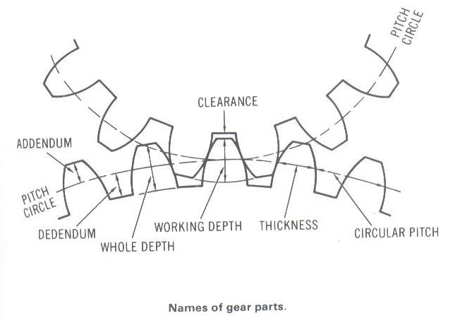 Figure 1. The first signs of pitting occur in the dedendum, the lower half of gear teeth. (Figure courtesy of Lawrence Ludwig, Jr.)
To counter this problem, original equipment manufacturers (OEMs) can increase the hardness of the gear, the gear’s face width or its pinion pitch diameter. Alternately, OEMs can improve the geometry of the gear.
The acronym LETS-C represents the four factors that contribute to gear failure and reduce gear life:
•
Load
•
Environmen
T
•
Speed
•
Contamination.
Features and failure
Some kinds of design features factor into distress and failure.
Hertzian strength, or beam strength, refers to the ability of a gear tooth to withstand repeated loadings. It is a measure of the load-carrying ability of a pair of gears. It has to be greater than the maximum dynamic load of the gear. Fatigue occurs when a gear is pushed beyond its capacity.
Thermal rating refers to the recommended maximum speed, reduction ratio and horsepower of the gearset. If the gear drive is used above those recommendations, the gear drive will start overheating.
This information can usually be found on the drawings, in the user manual or on the plates of the gearbox.
Backlash is a design feature that can affect lubrication. It is the distance between the back of one tooth and the front of the next mating tooth, as shown in Figure 2.
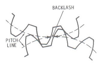 Figure 2. Backlash provides space for lubricants to keep gear teeth healthy. (Figure courtesy of Lawrence Ludwig, Jr.)
The distance allows the lubricant to coat the gear teeth. Without a good film of lubricant, the gears will overheat, create noise, suffer tooth wear and possibly fail. A rule of thumb for an appropriate amount of backlash is as follows:
•
Backlash = 0.04/diametral pitch of gear
•
Diametral pitch = the number of teeth/the pitch diameter.
Clearance also is needed for lubricant to flow properly between the gears. It is the distance between the top of one tooth and the base of the tooth on the other gear. It is a function of the height of the tooth and also is the amount by which the dedendum in a given gear exceeds the addendum of its mating gear.
Classes of lubrication-related failures:
•
Hertzian fatigue, both micro and macro
•
Wear
•
Scuffing, also known as scoring (or surface fatigue).
Different schools of thought break down gear failure into varying numbers of modes, as shown in Figure 3. For example, in this chart, tooth fracture occurs when the gear has been severely overloaded and failed.
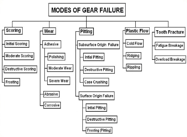 Figure 3. Gear failure can be broken down into five different modes. (Figure courtesy of NPTEL Course Machine Design II Lecture 6 Gear Failure; Indian Institute of Technology, Madras, India; professor K. Gopinath and professor M.M. Mayuram.)
Surface fatigue is a failure of gear material that has been under repeated surface or sub-surface stress beyond the material’s endurance limit. It indicates that Hertzian stresses are occurring when a gear and a pinion mesh. These stresses are above the beam strength of that gearset.
Surface fatigue forms include:
•
Pitting
•
Spalling
•
Case crushing.
Pitting
Pitting is the most common failure mode for gear teeth. It’s due to repeated loading and contact stresses exceeding surface fatigue strength of the material. Pitting can begin as soon as gears are put into operation.
Pitting comes in three types: initial, also known as corrective; destructive; and normal. All of these forms of pitting can take macro or micro forms. Macropitting refers to pits larger than 1 mm in diameter. Micropitting, also known as gray staining, include pits that are smaller than 10 microns in size. Micropitting causes the gears to look like it has white or gray frosting on the surface.
Initial pitting is caused by local areas of high stress due to uneven surfaces on the gear teeth. They are small pits less than 1 mm in diameter that can develop in a relatively short period of time. Pitting usually occurs in a narrow band at the pitch line or just slightly below the pitch line. It appears most prominently on through-hardened gears, occurs in localized areas and tends to redistribute load by removing rough areas with a high number of asperities.
Destructive pitting, also known as progressive pitting, results from surface overload conditions that initial pitting did not smooth out in the gearset. If tooth surface hardness is within specified values, system overloads are usually the cause of destructive pitting.
Destructive pitting starts below the tooth pitch line in the dedendum. It increases progressively in both the size and number of pits. It can eventually form fatigue cracks.
Ways to fix problem pitting include reducing the drive load, using a higher viscosity or different type of lubrication, upgrading the gearing or increasing drive size.
Figure 4 shows an example of macropitting in the dedendum of a pinion on the main hoist of a power shovel. Failure was caused by inadequate lubricant viscosity. The lubricant was much too light, at least two grades below what was recommended by the OEM. The image shows that much of the surface was undermined by subsurface cracks.
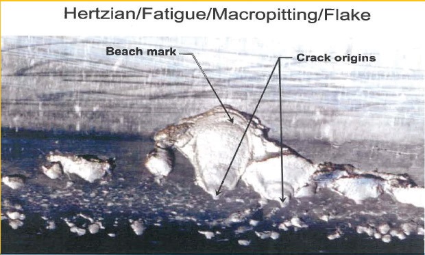 Figure 4. Macropitting results in material lost in the shape of arrowheads. (Figure courtesy of Lawrence Ludwig, Jr.)
Normal pitting appears as small or modest-sized pits covering the entire dedendum of the tooth flanks. Eventually pit rims occur with virtually no further pitting occurring. The pitting occurs because the orientation of the cracks in the dedendum of both the pinion and the gear can trap oil. As the contact rolls over the cracks, hydraulic pressure of the oil in the cracks causes the cracks to grow into pits (
1).
Pitting in the addendum higher on the tooth rarely occurs because the oil gets squeezed out of the microcracks before the contact can create the pit-causing hydraulic pressure.
Micropitting, also known as gray staining, contains pits less than 10 microns in size. The micropitted surface looks gray, white or frosted. The formation of micropits depends on factors such as material surface roughness and geometry, the type of lubrication, and operating conditions. It occurs on hardened tooth flanks of heavily loaded gears and consists of very small cracks and pores on the surface. Material is lost and changes the profile of tooth flanks, which leads to pitting and breakdown of the gears.
Micropitting is predominantly found in case-hardened (also known as carburized) gears. It alters gear tooth shape and concentrates the load over a smaller area, which affects the accuracy of the gears as they move through the mesh. Micropitting is often found in wind turbine applications.
Figure 5 shows an example of micropitting. Gear tooth surfaces must be illuminated at different angles to observe micropitting. Using intense direct lighting works better than diffuse fluorescent lighting.
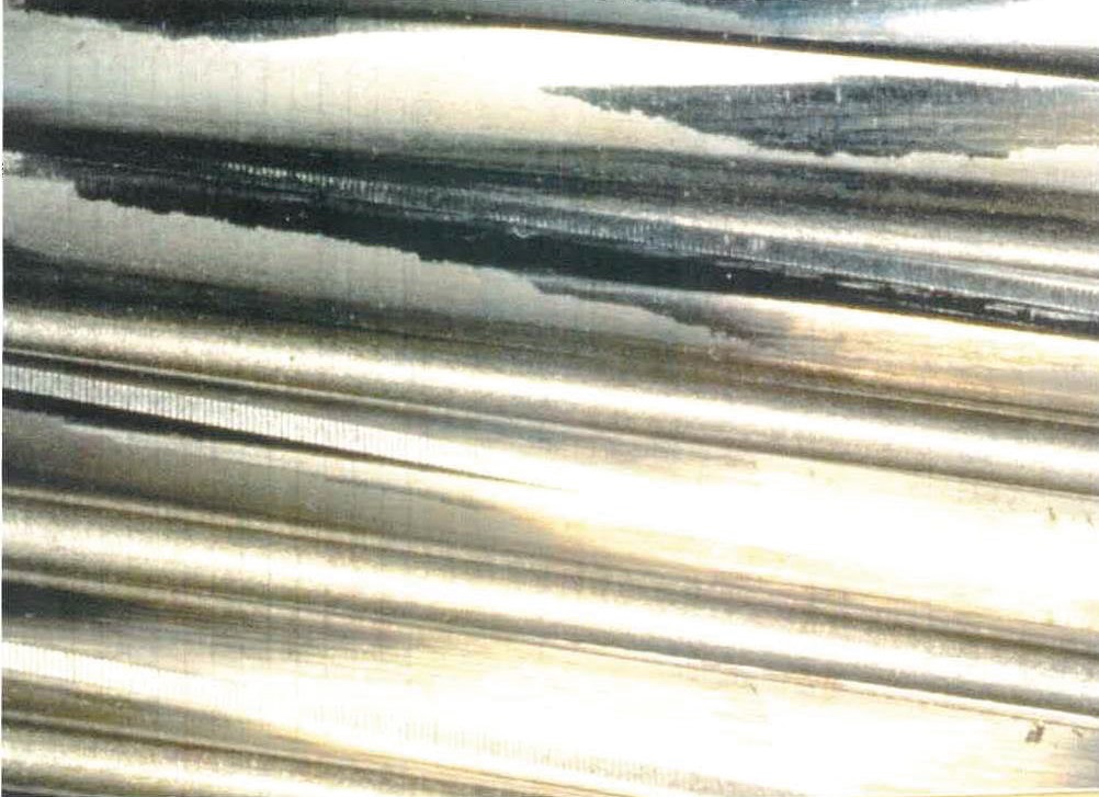 Figure 5. Micropitting can best be seen in direct lighting. (Figure courtesy of R. Errichello (July 2015), “Elastrohydrodynamic Lubrication (EHL): A Review,” Gear Technology Magazine. Available at www.geartechnology.com.)
Figure 6 lists different factors that influence micropitting. Ways to control it include having smooth surfaces on the gear teeth, operating under appropriate conditions and using lubricants designed to inhibit micropitting. Lubricants with a low coefficient of traction such as a PAO- or PAG-based oil will help reduce surface fatigue. Choose lubricants wisely because you don’t want to compromise other desired characteristics of your oil such as good wear and scuff protection or compatibility with seal materials.
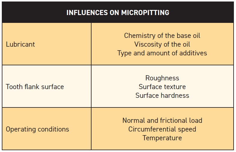 Figure 6. Lubricant, surfaces and operating conditions all influence the degree of micropitting. (Figure courtesy of Lawrence Ludwig, Jr.)
Spalling
Spalling describes a large area where the surface material has broken away from the tooth. It can appear as overlapping or interconnected large pits. With surface-hardened gears, it generally appears as loss of a single (or several) large areas.
Spalling is caused by high-contact stresses where the edges of initial pits break away and rapidly form large holes; for example, when macropits coalesce to form large craters. On the teeth in Figure 7, cracks have grown from the spall and reached the core/case boundary. The cracks continue under the topland and exit on the backside of the gearing, creating a hole all the way through the tooth.
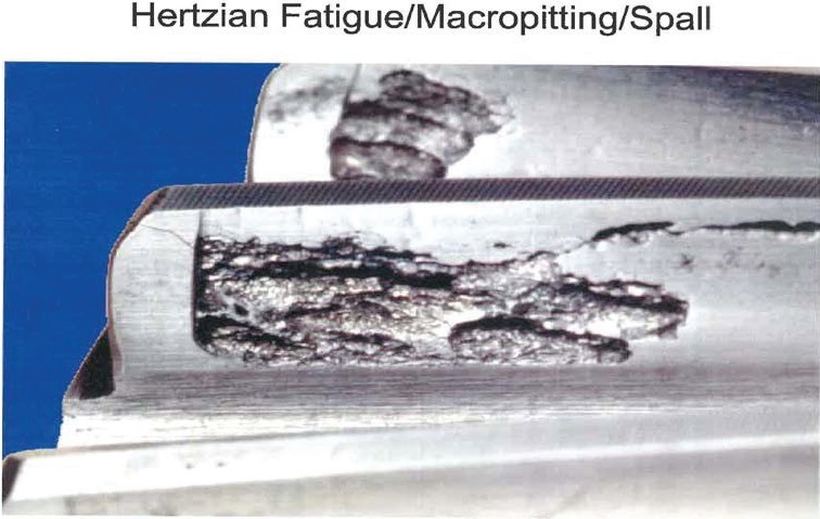 Figure 7. Large craters let cracks travel all the way through gear teeth, creating holes. (Figure courtesy of R. Errichello (July 2015), “Elastrohydrodynamic Lubrication (EHL): A Review,” Gear Technology Magazine. Available at www.geartechnology.com.)
Case crushing
Figure 7. Large craters let cracks travel all the way through gear teeth, creating holes. (Figure courtesy of R. Errichello (July 2015), “Elastrohydrodynamic Lubrication (EHL): A Review,” Gear Technology Magazine. Available at www.geartechnology.com.)
Case crushing
A type of spalling, case crushing, is associated with heavily loaded case-hardened gears. Case crushing appears as long longitudinal cracks on the tooth surface, which can cause pieces of the tooth to subsequently break away. Case crushing occurs suddenly on only one or two teeth of the pinion or gear. These cracks differ from pits because they not only extend below the hard case but can go clear through as shown in Figure 8.
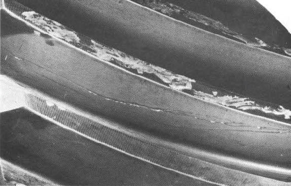 Figure 8. Case crushing is associated with heavily loaded case-hardened gears. (Figure courtesy of Failure Analysis: Gears-Shafts-Bearings-Seals, 108-010, August 1978, Rexnord Industries, LLC, Gear Group. Available here.)
Failure may be due to insufficient case depth, insufficient core hardness or high residual stresses. In many cases, failure is due to too much loading.
Wear
Wear describes loss of material from the contacting surfaces of a gear. Common causes of gear tooth wear include metal-to-metal contact from poor lubricating film, abrasive particles working their way into the gears, and chemical wear due to the composition of the gear oil and its additives.
Varying degrees of wear:
•
Polishing or light, which occurs slowly
•
Moderate or normal wear, also a slow process in area of dedendum
•
Excessive, such as destructive wear, which causes tooth shape to change and impairs meshing action.
Three types of wear modes include adhesive, abrasive and corrosive wear, with subcategories spanning:
•
Scuffing
•
Scoring
•
Scratching
•
Welding
•
Furrowing
•
Fretting corrosion
•
Cavitation
•
Erosion.
In adhesive wear, highly attractive forces of atoms occur on each of two contacting, sliding surfaces. Teeth touch each other at random asperities, forming a strong bond. Metal particles are actually transferred across the contacting surfaces. Transferred fragments fracture or fatigue away, forming a wear particle.
Scuffing is a severe type of adhesive wear that causes transfer of metal from one tooth surface to another due to welding. Scuffed areas have a rough or matte structure. Damage occurs in the addendum, dedendum or both in the direction that sliding is occurring. Under magnification, scuffed surfaces appear rough, torn and deformed.
Abrasive wear is sometimes called cutting wear. It occurs when hard particles make their way between the gears and slide or roll under pressure across the tooth surface. The hard particles can be dirt, castings, scale or even wear debris.
Corrosive wear is deterioration of the gear tooth due to chemical or electrochemical reactions. Chemical wear gives the tooth a stained or rusty appearance. Etched pits may appear as well. Unlike other types of wear, corrosive wear can be found on the entire tooth surface.
Common causes of corrosive wear include the chemical action of active ingredients in the lubricant such as sulfur, the presence of moisture or foreign materials in the lubricant and the extreme-pressure additives added to the lubricant that react with the gear teeth.
Breakage
Breakage is the ultimate type of failure. Breakage leads to a disabled drive and frequently to damage of other components such as shafts or bearings by pieces of the broken teeth. Breakage is the result of high overloads from impact or static. Misalignment of the teeth also can lead to tooth breakage. Fatigue fractures are the most common type of breakage, which arise from cracks at the root fillet that slowly progress.
Lubrication shortcomings
Lubricant issues can cause a variety of distress. Scoring and galling are generally caused by oil film breakdown, whether due to contaminants in the oil or too light of a viscosity which, in turn, allow metal-to-metal contact and high-operating temperatures.
Particulate contaminants present in the lubricant can cause abrasive wear. Pitting can sometimes indicate corrosive materials within the lubricant or improper type of gear lubricant being used, such as fuel oil in place of gear oil.
If a gear operates without adequate lubrication, damage will progress until gear teeth degrade and fail.
Troubleshooting and inspections
First, it is important to note that proper lubrication and lubrication practices help prevent gear failure. Most gear failures result from insufficient or interrupted lubrication, including such events as an insufficient supply of lubricant, using the wrong type of lubricant, contamination or foaming. Selection of proper lubricant is based on gear type; load, input power and reduction ratio; operating speed; and ambient and operating temperature.
Although you should always follow the OEM’s recommendations, the American Gear Manufacturers Association provides standards in AGMA 9005-E02 and AGMA 9000-F16. These documents lay out what type of gear lubricant should be used where and recommends lubricant viscosities based on gear speeds and loads.
Troubleshooting
To troubleshoot failures, take a root cause analysis approach using a team and working with your customer’s engineering and reliability staff. Then you will need to gather differ types of data while using appropriate methods of inspection.
Gathering data
•
Use an inspection form or appropriate document.
•
Record type of failure(s) that occurred.
•
Interview operators.
•
Record evidence; take pictures.
•
Review background information; look at service history and maintenance records.
•
Review gear drive assembly drawings and other drawings that may provide insight.
Methods of inspection
•
Begin with a visual inspection. Walk around and look through inspection ports.
•
Take temperature measurement, either infrared, RTD probe or thermography.
•
Do vibration analysis.
•
Inspect filters.
•
Use magnetic debris collectors.
•
Measure gear backlash and shaft endplay.
•
Record tooth contact patterns using dye penetrant.
•
Do lubricant analysis.
•
Document everything.
Figure 9 provides a list of items you will use to inspect a gearbox.
Equipment to Use for a Gearbox Inspection
•
Toothbrush for contact patterns
•
PT-650 Tooth Marking Grease for no-load contact patterns
•
DYKEM layout lacquer for loaded contact patterns
•
6-inch medium mill bastard file for recording graphite contact tapes
•
Drafting pencil with 2H lead for recording graphite contact tapes
•
Swiss army knife with scissors for recording contact tapes
•
Scotch No. 845 Book Tape for recording contact tapes
•
0.03 mm and 0.04 mm shims
•
Felt-tip paint marker
•
Ear plugs
•
Sweatband
•
Toolbelt
•
Metric/inch tape measure
•
Tweezers
•
Spatula
•
Telescoping magnet
•
Leatherman “super tool”
•
High-intensity LED flashlight
•
Fiber-optic attachment for LED flashlight
•
6-inch metric/inch scale
•
3.5-inch magnifier
•
2-by-3.5-inch telescoping mirror
•
30X Panasonic Light Scope microscope
•
Torque wrench
•
Dial indicators with magnetic bases
•
Inspection forms
•
Lubricant sampling equipment
•
Baggies and tags for specimens
•
Micrometers
•
Borescope
•
DSLR camera with close-up flash
•
Sound meter
•
Vibration probe
•
Digital thermometer
•
Infrared thermometer or infrared imaging camera
Figure 9. Pack these tools along for a gearbox inspection. (Figure courtesy of Lawrence Ludwig, Jr.)
For the visual inspection, first take a walk around and look for signs of overheating, corrosion, contamination, oil leaks and damage. Also look for evidence of movement such as cracked paint or fretting corrosion on bolts, structural fasteners and interfaces. Inspect breather and check shaft seals.
For the inspection ports, check to see if bolts are tight and the cover is properly sealed. Only qualified personnel should be allowed to open the inspection port using proper lockout and tagout procedures. Observe the condition of the gears, shafts and bearings, and examine the gears with magnetic particle inspection equipment.
Signs of overheating:
•
Smoke from shafts, seals or breathers
•
Discolored or burnt paint on housings
•
Tempered colors on unpainted surface
•
Low oil level in sight glass or dipstick
•
Foaming present in sight glass or coming out of the breather
•
Dark color oil
•
Foul or pungent odor or acrid smell
•
Water in sight glass or sludge on filter elements
•
Blueing on metal chips on magnetic plugs, chip detectors and filters.
Create an overheating detection checklist that includes:
•
Visual signs of overheating.
•
Record operating temperatures from gearbox thermometers or from temperature probes, infrared thermometer or infrared imaging taken at 0%, 50% and 100% load; shoot the probe diagonally across housing—if 5 C (10 F) difference, this is sign of misalignment.
•
For pressure-fed systems with oil cooler, measure temperature at gearbox oil inlet and outlet, as well as cooler water inlet and outlet.
•
Inspect internal gearbox components.
•
Measure gearbox sound and vibration and compare to allowable limits.
•
Take oil samples for analysis.
Gear backlash and shaft endplay
Measure gear backlash by mounting a dial indicator so it is similar to a pinion tooth profile. Block the gear to prevent its rotation. Slowly and gently rock the pinion through the backlash.
Also measure shaft endplay by mounting a dial indicator at the end of a shaft and move the shaft in the axial direction. In most cases, this requires a fixture with a ball bearing on the central shaft that allows pushing and pulling the shaft while it is rotated to seat the bearing rollers.
Gear tooth contact patterns
Contact patterns can reveal gear mesh misalignment. Optimally, examining them should be done during commissioning of a gear drive and regularly during use, once every year or two. You also should examine them before disassembling a gear drive for repair or inspection.
To do so, run contact pattern tests under unloaded and loaded conditions. As always, gather evidence—record, document and photograph gear contact patterns.
To examine unloaded patterns, thoroughly clean and paint the teeth on one gear with a soft marking compound such as a tooth-marking grease. Roll the teeth through the mesh so the compound transfers to the unpainted gear. For example, turn pinion by hand while applying a light load to the gear shaft by hand or a brake. Lift the pattern from the gear with scotch tape (#845, book type, two inches wide) and mount on paper to form a permanent record.
Figure 10 shows the marking of an unloaded gear pattern transferred to scotch tape. The image shows that the contact is wandering from center, to the left end of the gear face. Misalignment is occurring.
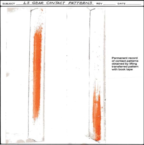 Figure 10. This unloaded gear pattern on tape shows misalignment. (Figure courtesy of Lawrence Ludwig, Jr.)
To examine loaded patterns, paint several teeth on one or both gears with a thin coat of machinist’s layout lacquer such as Dykem. Run the gears under load at 25%, 50%, 75% and 100% of full load. Inspect the patterns after running about one hour at each load. Optimum contact patterns will cover nearly 100% of the active face of the gear teeth under full load. Photograph the pattern and lift pattern from gear with scotch tape and mount on paper to form a permanent record.
Figure 11 shows the pattern of a gear at 50% load (left) and full load (right).
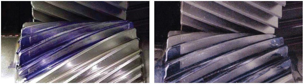 Figure 11. Patterns differ at 50% load (left) and full load (right). (Figure courtesy of Lawrence Ludwig, Jr.)
Published profiles will show you what to look for, as in Figure 12. For example, (a) shows what the pattern looks like if the pinion is wobbling.
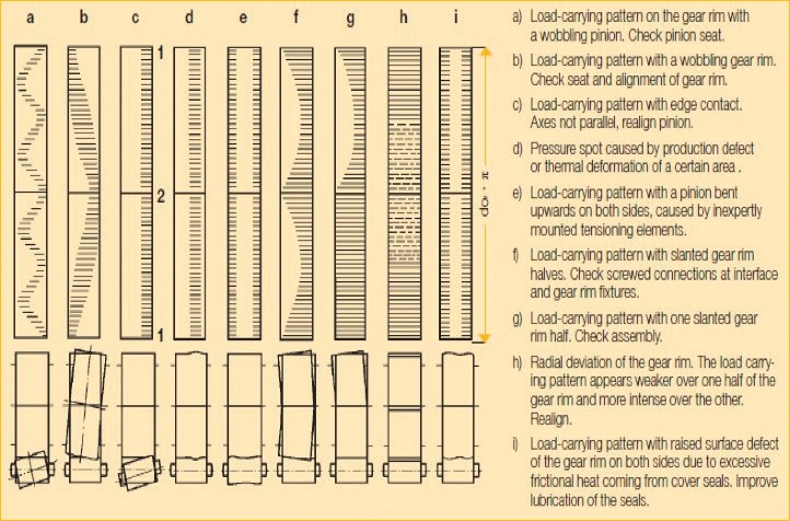 Figure 12. These patterns demonstrate different kinds of irregular wear. (Figure courtesy of Lawrence Ludwig, Jr.)
Lubricant analysis
Figure 12. These patterns demonstrate different kinds of irregular wear. (Figure courtesy of Lawrence Ludwig, Jr.)
Lubricant analysis
It’s also important to analyze oil samples from a failed gearbox in the laboratory and compare it to an unused sample. Such analysis might reveal whether the oil meets the OEM specification, whether it was contaminated or degraded and whether it is representative of the service oil. The oil might contain evidence for finding the root cause of failure.
Lubricant analysis tests to perform:
•
Visual inspection
•
Odor
•
Crackle test on a hot plate to see if it contains moisture
•
Viscosity at 40 C ASTM D445
•
Spectrometric analysis ASTM D5185 or D6595
•
FTIR
•
Karl Fisher ASTM D6304
•
Acid Number ASTM D664
•
Ferrographic Analysis
•
Particle Count ASTM D7647
•
RULER Method (Linear Sweep Voltammetry).
Sampling procedure
Take an oil sample from as close to the gearset as possible by using a sample port. A sample port such as a Minimess made by Hydrotechnik GmbH has a 12-inch tube extension that can be mounted in the drain and can terminate where you choose. A rule of thumb for installation is to keep the end of the tube at least two inches away from any internal static or dynamic surface. Flush the port and tube at least 10 times before taking sample for analysis, about 3-4 ounces of fluid.
If taking samples by draining the oil reservoir, take at least three samples. For the first sample, drain the oil through a screen to capture any large wear debris or fracture fragments that might be entrained. Let any free water drain completely before capturing sample. For the second sample, take near the middle of drain. Estimate oil level in the gearbox from the sight gauge or from direct measurements. Take the third sample near the end of the drain. This sample might capture less-dense contaminant fluids.
Document everything
It’s important to document the entire team’s work. Describe all important observations in writing. Attach sketches, photographs and oil analysis reports where needed. Identify and mark each component, including gear teeth and bearing rollers. Mark all bearings including inboard and outboard sides.
Describe components in a consistent manner. Progress through the parts in the same sequence. Concentrate on collecting as much evidence as possible. Do not form conclusions until all the evidence is considered and documented.
REFERENCE
1.
Failure Analysis: Gears-Shafts-Bearings-Seals, 108-010, August 1978, Rexnord Industries, LLC, Gear Group. Available
here.
Mary Beckman is a free-lance science writer based in Richland, Wash. You can contact her at mbeckman@nasw.org.