Bearings today perform under higher loads, speeds and temperatures.
The application dictates how bearing designers prioritize failure rate, operating conditions, life span and cost.
Computational models expand capabilities for materials development, bearing design and performance predictions.
“Everyone uses bearings, and if I do my job right you don’t really have to think about them,” says STLE-member Bryan Allison, a product development engineer with SKF Aeroengine North America. Bearings are in everything from ATM card readers to zoo turnstile gates. The tiniest bearings, just a few millimeters across, are found in medical and dental instruments and model cars. The largest bearings can be more than 10 meters across—one behemoth, used in an offshore oil drilling rig, is 18 meters in diameter.
Bearing geometry hasn’t changed much over the past 100 years, so it’s the materials that change, says Allison. Today’s demand is for bearings that perform under higher loads across a broader temperature range at reduced weight and cost.
Different applications, different bearings
The size of the bearing, the size of the load and its axial and thrust components, the speed at which the rolling elements move and the operating environment all play roles in the choice of bearing geometry, materials and lubricants. Selecting bearings that meet performance needs without excessive costs requires optimizing the balance between expected service life, time and expense for maintenance and repairs and the severity of the consequences if a bearing fails (
see Figure 1).
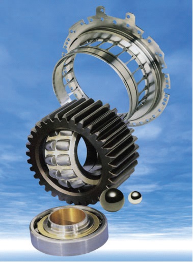 Figure 1. Some of the many types of bearing components include (top to bottom) flanged outer ring with squirrel cage, spherical roller bearing with geared outer ring and ceramic rollers and cylindrical roller bearing with ceramics. (Figure courtesy of SKF.)
Bearings are designed to last for many years, but they can fail suddenly from a process that starts on a microscopic scale under the metal’s surface and propagates to the surface over a span of years. Once a bearing fails, however, it can damage or destroy other components or an entire system. It’s difficult to predict when a bearing will fail, and even more difficult to detect failures at an early enough stage to take actions that will extend a bearing’s life.
Reliable performance takes precedence where the consequences of part failures are high. The expense of high-performance materials is an acceptable trade-off for the added security they provide. Allison works mainly on developing and qualifying new materials to meet the demands of the aircraft industry. For airplanes and helicopters, “zero failures are acceptable,” he says. The aerospace industry requires a long L
10 life—a statistical measure of how long it takes for 10% of a particular type of component to fail—because the cost of failure is higher for aircraft than it is for ground vehicles. “A [failed] bearing on the wheel of your car is an inconvenience; you have to pull over and get towed, but it’s nowhere near as bad as a helicopter or plane falling out of the sky,” he says.
Long service lifetimes take precedence when the cost of replacing a bearing is high. STLE-member Anup Pandkar, a scientist at Sentient Science Corp., specializes in computational methods related to wind turbine applications for energy generation. Sentient Science offers digitalization services to industrial equipment manufacturers and operators, including model-based predictive indicators that alert operators that it’s time to take preventive action on a specific component—a main bearing or gearbox bearing in a wind turbine, for example. This helps customers save money, not only by replacing bearings before they fail, avoiding damage to other components of the drivetrain or unplanned turbine downtime, but also avoiding expensive over-maintenance from replacing bearings too soon.
Cost is the driving factor for everyday applications like the bearings in bicycles, washing machines and fishing reels. These bearings operate under relatively low loads and speeds, and failures are more annoying than catastrophic. Replacement parts can be ordered from a catalog, and today’s steels and other materials provide good performance at a nominal cost.
Materials and manufacturing
Bearings have come a long way since World War II, when the steel used to make them would often contain voids and slag inclusions. Since that time, steel quality has significantly improved, as have bearing production methods, heat treatments and surface treatments and coatings.
Manufacturing methods are changing, says Allison. Bearing components aren’t changing much, but the way they are made is. For example, powder metallurgy can be used to produce parts with very long lives, using new alloys that can’t be made with traditional casting methods. Computations can be used to design raceways with a high-performance material on the surface and a cheaper material below, he adds (
see Figure 2).
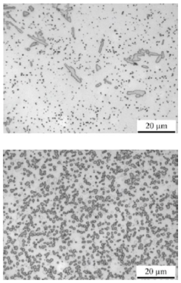 Figure 2. Manufacturing processes influence the distribution of carbide particles in steel. Top: A typical forged M50 steel. Bottom: A powder metal steel with improved fatigue resistance. (Figure courtesy of SKF.)
Steel is still the most common choice for bearing components, but other materials come into play for specific applications. Overall there is a trend toward more durable rolling components that can carry higher loads. High-speed steel grades made using powder metallurgy, for example, have been around since the 1970s, but subsequent developments in alloy composition, high-cleanliness steel melting and heat treatment have increased the metallurgical integrity of these steels (
1).
Choosing a bearing material (or combination of materials) requires customers to balance their priorities for application requirements, performance (e.g., maximum load, wear resistance and performance life) and cost. Rolling bearing steels like 100Cr6 are fairly standard, but manufacturers can choose from a wide range of compositions, microstructures and treatments to match the material to the application.
Bearing alloys, microstructures, heat treatments and structural configurations that are chosen to fit a specific application can minimize various failure modes. For example, M50-NiL steel, with its high nickel content, is strong and tough, Pandkar says. These properties are important for operations at higher speeds, which produce higher centrifugal forces on a shaft. Other alloys are chosen to suit operations in subzero temperatures or for long lifetimes and high reliability, he says (
see Figure 3).
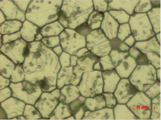 Figure 3. Grain structure in M50 bearing steel. (Figure courtesy of SKF.)
Martensitic thorough hardening produces a hard steel with well-dispersed carbon. Bainitic hardening retains residual compressive surface stresses that increase fracture toughness. For other applications, case hardening (forming a hard carbide or nitride layer at the surface of a softer low-carbon steel), or induction hardening (which forms a martensitic surface) produce the desired properties and performance.
For ordinary bearings, a thin nitrocarburized surface region can improve wear resistance. This is especially important in engines and gearboxes that use low-viscosity oils, which provide a thinner lubricating film. Heat treatments or tool-hardened materials also can provide higher wear resistance. Both types of treatment increase wear resistance for just a small increase in cost, but they do not provide a longer fatigue life.
Extending the fatigue life of a bearing requires deeper nitrocarburization. Cronidur 30, for example, is a fine-grained stainless steel that is pressure-nitrided and undergoes a specialized heat treatment. The steel is made using a powder metallurgy process under a nitrogen atmosphere, which incorporates nitrogen throughout the steel rather than only on the surface. This steel was developed for the fuel pumps in the Space Shuttle, and it also is used in some aircraft and other specialty applications.
The extra expense of this steel can pay off, however. Martin Correns, senior expert in the Department of Advanced Engineering Analysis and Simulation for Schaeffler Technologies AG & Co. KG (Herzogenaurach, Germany), notes that the first Space Shuttles required fuel pump replacement after every flight. Cronidur bearings allow NASA to use the same fuel pump for as many as 20 missions, he says, even in the harsh chemical and thermal environments typical of launch, space flight and re-entry.
Other high-performance applications use diamondlike carbon coatings on bearing raceways to reduce friction and increase life in situations where there is poor lubrication or lubricating films are thin. Correns notes that it’s not easy to put a diamondlike coating on a rolling contact because of the large difference in modulus between the coating and the steel, which can lead to delamination, so these coatings are not economical for ordinary use.
Ultraclean steels, heat treated under a vacuum, are useful in high-performance applications, but today’s ordinary steels suffice for most everyday uses. “Large inclusions can lead to premature failure, but these shouldn’t be in your steel in the first place,” says Correns. “Smaller inclusions don’t have as much of an effect because steel is already a mixture of grains,” he adds. However, bearings under very high stress (4,000 MPa or more), like those in the automatic transmission system for a high-performance car, can benefit from using ultraclean steels. Bicycles, vacuum cleaners and power drills generally operate in much lower stress range, and “catalog level bearings” provide the needed level of performance for a more reasonable cost.
Cost reduction also can be achieved by using ordinary materials for bearing cages and outer rings and high-performance materials for the inner rings. Dedicated diamondlike coatings or black oxide coatings applied over a standard material can enhance the performance of the inner rings still further, while keeping costs low.
Steel isn’t the only game in town, however. There’s a big push in the aerospace industry for weight reduction, Allison says. Ceramic rolling elements (e.g., silicon nitride or zirconia) weigh about 40% as much as steel. Aluminum-titanium alloys or polymers can be used for lightweight bearing cages, but the raceways are still mainly made from steel (
see Figure 4).
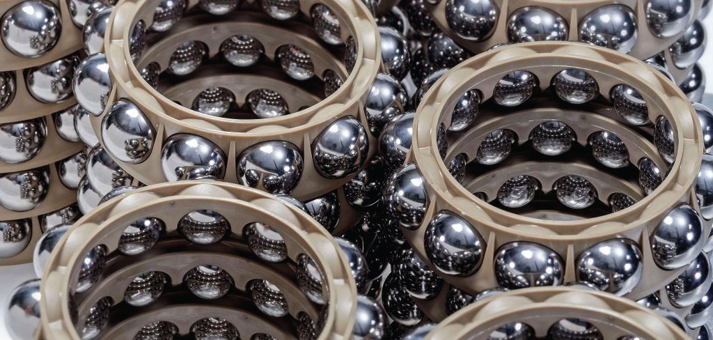 Figure 4. These bearing cages are made from PEEK polymer. (Figure courtesy of SKF.)
Because ceramics are twice as hard and about 30%-50% stiffer than steel, Allison continues, ceramic rolling elements can “heal” minor damage in steel bearing rings by buffing out asperities; they plastically deform the steel back to a flat surface. Ceramic rolling elements also require less lubricant than their metal counterparts, he adds. In the late 1980s, ceramic rolling elements became popular for the bearings in high-speed machine tool spindles. Now other industries including aerospace and wind turbines are adopting ceramics as well, he says (
see Figure 5).
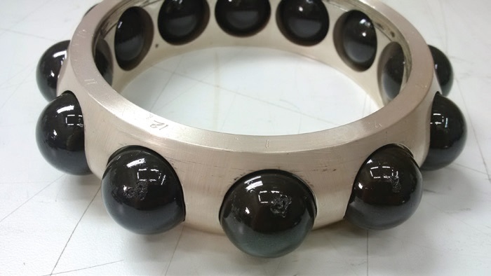 Figure 5. Ceramic balls in a steel cage. (Figure courtesy of SKF.)
Failure causes
Figure 5. Ceramic balls in a steel cage. (Figure courtesy of SKF.)
Failure causes
Manufacturing processes, heat treatments and inspection methods ensure that even mass-produced steel parts are more reliable now than they were in the past. However, unexpected failure is still a problem for wind turbines, says Pandkar, adding, “Bearing manufacturers want to understand the root cause of such failures and how to prevent them. This is a major concern.”
Rolling contact fatigue (RCF) is traditionally how bearings fail, says Allison. Because the contact area between the rolling element and the raceway is so small and forces are so high, the contact area experiences very high pressures. High pressures and cyclic loading create ideal conditions for fatigue, which begins on the microstructural level.
RCF failure usually occurs on the inner ring in a raceway, Allison says. “You’re running the ball over the same spot on the ring billions of times.” Rolling elements also can fail due to RCF, but because there are several rolling elements in a bearing, and only one ring, each rolling element experiences fewer stress cycles than the ring does.
The region of maximum stress in an inner ring is about a half millimeter below the surface, Allison says. Steel generally contains nonmetallic inclusions, including carbides. Cracks begin next to these inclusions and grow upward toward the surface.
Surface nitriding can reduce both RCF-induced hardening and the size of the affected regions, and surface mechanical processing reduces these still further. Another way to slow crack initiation and growth is by inducing compressive residual stress during or after manufacturing (
2).
RCF can be reduced by using cleaner steels; that is, steels with fewer inclusions. In the 1940s, essentially all bearings failed due to RCF, Allison says. Now only about a third of industrial bearings and 5% of aerospace bearings fail because of RCF, he adds, explaining that surface-initiated damage like wear or third-body contamination is a more likely cause of failure in modern bearings.
White etching cracks are another cause of bearing failure. Especially in wind turbines, these cracks can cause a bearing to fail before it reaches half of its design life, says Pandkar. White etching cracks are surrounded by areas of recrystallized ferrite with few to no carbide particles. These microscopic ferrite areas, which appear white in a polished, etched steel sample, are harder than the surrounding steel matrix. The cracks generally nucleate below the surface and propagate upward, eventually causing spalling. Bearing specialists have studied this phenomenon for decades, but there is still no consensus as to the root cause and failure mechanisms behind it (
see Figure 6) (
3).
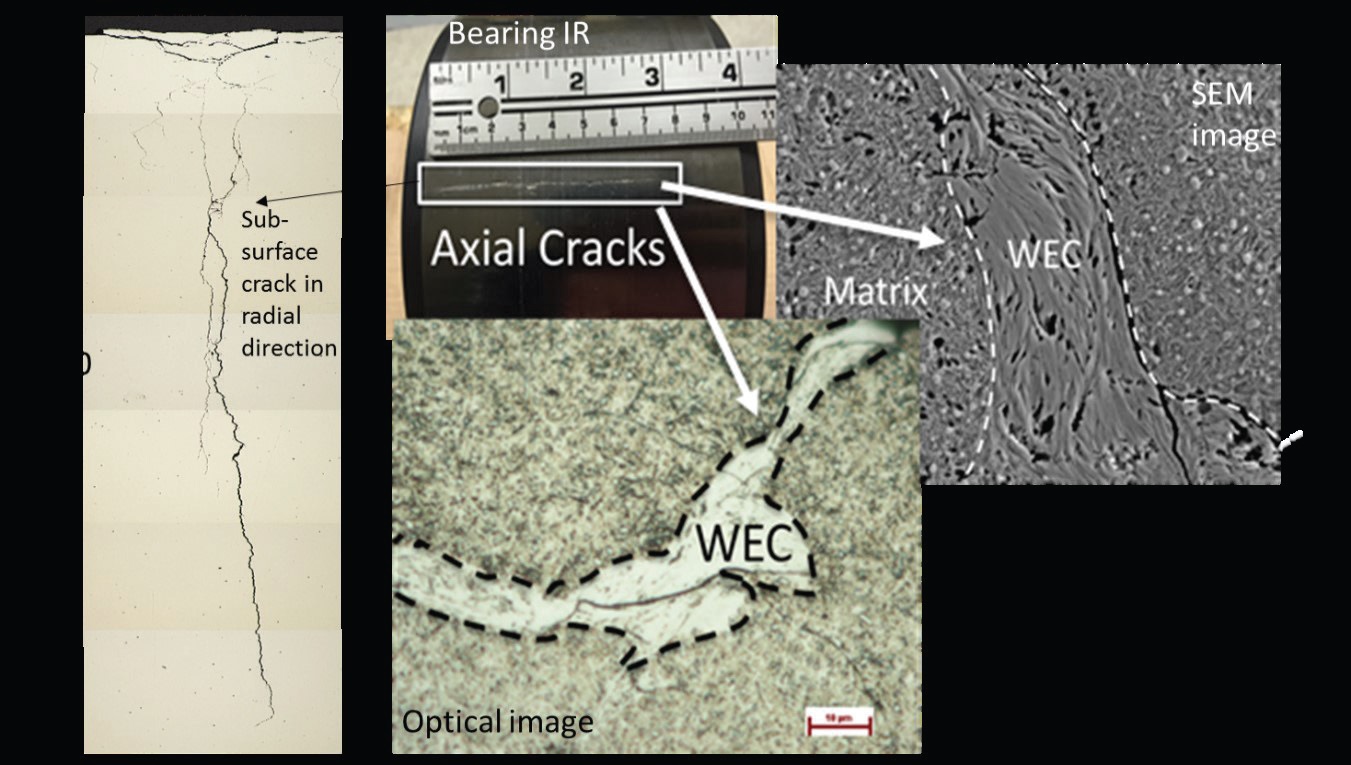 Figure 6. Cracks nucleate below the surface of a bearing steel, driven by microstructural alteration during normal wear. WEC means white etching crack. (Figure courtesy of Sentient Science Corp., Ref. 4.)
Computational models can give customers advance warning of impending component failures. These models form the basis of digitized systems that continually monitor equipment in the field for small signs of abnormal behaviors that indicate something is beginning to go wrong. Such a system can alert an operator to take preventive or corrective action or to begin planning for these actions.
For wind turbines, the emphasis is on preventing premature bearing failures. Once a problem is big enough for an equipment sensor in the field to pick up, it’s too late to take preventive action, Pandkar says. However, an over-cautious approach to bearing maintenance and replacement can drive costs up unnecessarily, both from replacing parts prematurely and from the down time required.
A requirement for zero failures, typical of aerospace applications, means taking parts out of service before they have a chance to fail. This requirement also limits designers’ ability to field test new materials. Tolerating a small risk of failure could cut costs, but “no one wants to try something and put it on a plane and then have it fail,” Allison says. The challenge is to find the best balance between long service life and zero failures.
Computational areas that need work include the prediction of wear, micropitting and gray staining (which is not a material failure but could propagate to surface-induced fatigue). With lubricant viscosities going down, lubricant films are getting thinner, and customers need a way to decide when they need special coatings or lubricants. “You need the calculations to make these decisions,” Correns says.
Reducing friction
Much of the development work over the past 20 years has gone into reducing friction in bearings, Correns says. “Everybody wants to conserve energy to reduce their carbon footprint.” Reducing friction does more than reduce fuel consumption, however. Heat from friction reduces the thickness of a lubricating film, so friction reduction can reduce wear and extend bearing life.
The modeling and simulation aspect of bearing design still has room for improvement, Correns says. “We have done a lot of work on friction reduction, and we have some good calculation capabilities, but there is still room for improvement, for example, in modeling contacts between rollers and flanges to optimize internal design.”
Better bearings aren’t the only factor in improving performance, says Pandkar. Proper lubricant maintenance can prevent debris and contaminants from damaging the bearings and contributing to premature failure.
Modeling the effects of lubricant contaminants is an area under development. Solid particles can leave imprints in a bearing raceway, which can deform and harden the steel. Even something as seemingly innocuous as a cotton fiber in a textile mill can imprint a steel raceway because of the high pressure between the ball and the raceway. Understanding the effects of particle size, hardness and ductility and other factors helps in interpreting the results from a test rig.
Manufacturing processes play a role in fatigue life and performance, especially for the raceways. Precision manufacturing methods make raceways that are straighter and less wavy on a micron scale. This reduces friction and vibration significantly, especially in high-speed applications. Proper alignment between the bearing and shaft also minimizes vibrations, which improves performance and extends life. Less vibration not only reduces noise, it also reduces stress on the bearing, which makes it last longer.
Computation extends capabilities
Computational simulations can help at every stage, from selecting materials and designing bearings to predicting their performance in the field. Whole-system simulations, for example, model bearing geometry and surrounding structure. This type of simulation reduces the amount of testing necessary to validate bearing designs for a given application and provides insight into the critical variables for performance. Other computational approaches deal with the physics of failure mechanisms and prevention. “You can’t capture everything,” says Allison, adding, “We don’t know all the variables that we
should try to capture.”
Regardless of the customers’ priorities, an accurate analysis requires that computational models combine basic physical principles, tribology, mechanics, materials science and multibody dynamics with load measurements, environmental conditions and information on the age and usage of each part being monitored. Sooner or later, however, simulations must be validated in the real world. “Right now, we over-engineer parts to build in a safety factor,” Allison says. This could involve using larger bearings than necessary. However, with the push toward weight reduction in the aerospace industry, “We’re taking advantage of new materials to let us use smaller bearings,” he says. This leaves less room for error, which makes validating computations even more important.
“A lot of our work is on optimizing stresses, and that’s where computation comes in,” Allison explains. Experimentally, this would take thousands of tests to determine optimum stress profiles and the effects of geometry and inclusions in the steel. Computation reduces the number of experimental tests, he says.
Computation can simulate a bearing’s lifetime more quickly than real-time experiments. Materials last 20-30 times longer now than they did just 20 years ago and hundreds of times longer than in 1930s and 1940s, Allison says, so lab tests have to last longer. Testing a part to failure is impractical, he adds, because the normal design life of a bearing under normal conditions is 50,000 hours (5.7 years). “We would have new materials by the time the test was finished,” he adds. “We generally just run one ball to failure and compare it to a baseline material,” he says.
Computation enables developers to simulate various materials, heat treatments and other variables in a reasonable amount of time. Computation also allows developers to predict failure times and mechanisms by extrapolating information from partially worn parts. “We can run a ball for 1,000 hours,” Allison says, “and then cut it up and look at the microstructure—how close to failure is it?”
Correns notes the difficulty of setting up an instrument and extracting data from the interactions between a bearing ball and cage. “How many cage properties do you want to measure?” he asks. “If you measure one ball, is it the same as measuring all of them?” Simulations and calculations are a much easier alternative to lab measurements, he explains. “Solid fundamental research combined with tested, validated models produces a valid simulation.”
Statistical simulations
Statistical evaluation is necessary to account for the inevitable variability in performance that comes from using steel. Even for identical parts made from the same steel using the same manufacturing conditions, you can’t predict exactly when a bearing will fail because they all behave differently, Correns explains. Steel is heterogeneous, and there’s too much variability even if you use a standardized test rig and rigorously controlled operating conditions. You can calculate the probability of failure for a bearing that has seen a particular load spectrum, he says, but you can’t say, “This bearing will fail tomorrow.”
For a bearing with a 10% probability of failure (L
10) of 5 years, the L
50 would be 27 years, and the L
90 would be 78 years, Correns says. For a span this big, a Big Data approach doesn’t help. You could test 100 identical bearings under the same conditions and still have fatigue times spread over a factor of more than 20, he explains, citing a researcher in Japan who tested 1,000 bearings and found that the failure times varied by a factor of nearly 100.
This is because steel grains are different in each bearing even if the manufacturing process is the same. “It’s not the manufacturing process, it’s the steel,” Correns says. Even polished standard test parts in a test rig give the same failure distribution pattern and the same variation of results, he notes. Correns cites STLE Life Member Farshid Sadeghi, a professor at Purdue University, who modeled rolling contact fatigue as a function of grain structure. Even in this theoretical situation, there was a distribution of results that matched the distribution seen in actual life tests, Correns adds. Each grain orientation and each type of boundary cohesion reacts to loads differently, so even a uniform load gives different test results. “That’s just the nature of fatigue. We can’t get away from this, so we have to use proper statistics, which gives you a probability, but can’t predict a single event,” he says.
Research computations
Research-level calculations go far beyond what is required for catalog parts or standard classroom methods, says Correns. “We can do quite sophisticated calculations of sliding and spinning motions in detailed models to calculate the actual friction torque of a bearing,” he says. “We have quite a good correlation between what we calculate and what we test.”
Ordinary calculations of geometries, temperatures and stresses can be done on an office computer. However, research-level microstructure statistics on hundreds of models and materials with many defects require supercomputers or computing clusters. Research simulations reduce the time and expense needed for physical testing (although physical tests are still necessary to validate the models). Well-designed simulations yield information on processes that are difficult or impossible to test in the lab or field.
Service life prediction is still a hot topic, Correns says. The current standard life calculation methods are good for about 99% of applications, he adds, but they are based on the assumption that you’re dealing with a homogeneous material. On a research level, you need to simulate the internal microstructure, which requires accounting for fracture mechanics and the distribution of inclusions. This level of detail assists with selecting materials and determining surface properties and levels of cleanliness, which in turn helps improve everyday calculations like determining the partitioning between micropitting and surface-induced fatigue at very low film thicknesses.
For simulating RCF, the challenge is in the process itself, Pandkar says. RCF-induced failures initiate in an extremely localized volume of a bearing raceway that is subjected to triaxial, non-proportional fatigue loads. At this length scale, microstructure plays a crucial role, and it evolves with time. Thus, accurate model inputs are needed to improve the predictions of the bearing’s microscale response under macroscale loads (
see Figure 7).
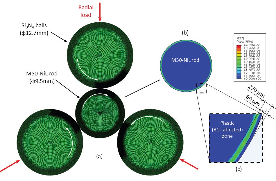 Figure 7. Finite element analysis (FEA) simulation of an accelerated three ball-on-rod RCF test showing RCF-affected region in case-hardened M50-NiL bearing steel. (a) 2D plane strain FEA model subjected to 5.5 GPa Hertzian contact stress. (b) Plastically deformed region in the form of a circumferential ring developed in the subsurface of test rod. (c) Magnified view of the plastic zone (RCF-affected region). (Figure reprinted from Ref. 5, with permission from Elsevier.)
Understanding specific failure modes enables designers to develop microstructures, heat treatments and structural configurations that minimize these modes. Pandkar notes the importance of providing good inputs to a model in order to simulate bearing responses that more closely resemble those in the lab or the field. “We need to correctly simulate the material microstructure,” he says. This includes accurate descriptions of steel grains, inclusions and grain boundaries as well as their interfaces and interactions.
Steel microstructures evolve over time as a bearing undergoes cyclic loading, temperature fluctuations and all other factors associated with bearing operation. “We don’t clearly know how to model the evolution of material microstructure yet,” Pandkar says, “so we need better inputs such as constitutive material properties and knowledge of inclusion morphology to create more sophisticated models that can accurately simulate the microscale material responses and evolution.” However, you can’t model everything, he adds. Because there’s a statistical element associated with microscale properties of bearing, you need a statistical way to interpret the modeling results.
Even though much work remains to be done on developing detailed, accurate models of bearings and systems currently in use, new developments on the horizon, including electric vehicles and additive manufacturing, promise even greater challenges (
see Additive Manufacturing).
 © Can Stock Photo / MarinaSk
Additive manufacturing
© Can Stock Photo / MarinaSk
Additive manufacturing
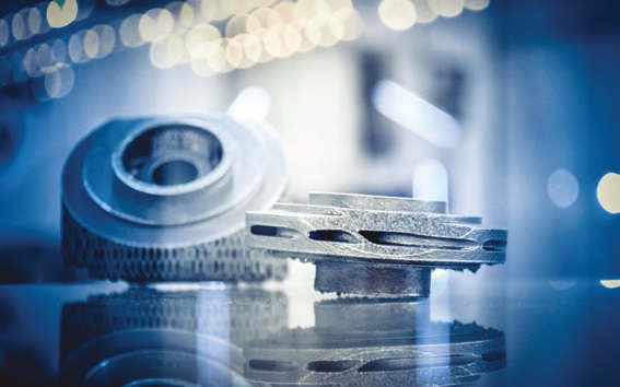
Additive manufacturing (commonly known as 3D printing), is revolutionizing the industry, Allison says. Not only is this method changing the way things are made, but the method itself is going through a revolution in speed, precision and the types of materials used (including metals). “The technology is there,” he says, “how do we use it?”
The push toward weight reduction is making designers look at what noncritical sections they can cut out and still have a reliable bearing, Allison says. With traditional machining methods, it’s not possible to cut out certain sections, but with additive manufacturing you don’t put that section there in the first place. The technique can be used to make geometries that aren’t possible (or would be difficult or expensive) using conventional methods. Computations let developers find the sections they can cut out without reducing performance, he says.
Although additive manufacturing is still slower than conventional mass production, in the aerospace industry, “full-scale production” often means 20-50 parts per year, compared with hundreds of thousands of parts in the automotive or locomotive industry, Allison says. Not only that, but printing speeds are increasing at a rapid pace, he adds.
Additive manufacturing allows developers to make prototypes with internal holes and other structures that wouldn’t be feasible using ordinary manufacturing, and it can be used to make parts from polymers, metals and other materials, Correns says. The resulting parts have different material strengths and plastic flow limits than parts produced conventionally. The effect is more pronounced for metal parts, which are more brittle than those made using conventional manufacturing, Correns adds, so it’s not yet feasible to make metal raceways using additive manufacturing. Some research is being done on applying multiple layers of coatings onto an ordinary steel base, but the total process is too slow and expensive to use for mass production, he says.
Bearings may be an old technology, but new applications in the field continue to place new demands on materials and designs. Computational modeling helps materials developers as well as systems operators keep things running smoothly.
REFERENCES
1.
Allison, B. D., et al. (2017), “New Class of High-Speed Steels for Aero Rolling Bearings,” ASTM Committee/Subcommittee A01.28, STP 1600, DOI: 10.1520/STP160020160131. Available
here.
2.
Bhattacharyya A., et al. (Jan. 21, 2016), “Influence of Residual Stress and Temperature on the Cyclic Hardening Response of M50 High-Strength Bearing Steel Subjected to Rolling Contact Fatigue,”
J. Eng. Mater. Technol,
138 (2), 021003, DOI: 10.1115/1.4032321. Available
here.
3.
Stadler, K., Vegter, R. H. and Vaes, D. (Jan. 23, 2018), “White Etching Cracks,”
Evolution: Business and Technology from SKF. Available
here.
4.
Singh, H. (May 2017), “Wind Turbine Gearbox Bearing Material Analysis to Study Crack Nucleation, Propagation and Damage Mechanisms,” STLE 72nd Annual Meeting, Atlanta, DOI: 10.13140/RG.2.2.27415.83367.
5.
Reprinted from
International Journal of Fatigue, Vol. 63, A. S. Pandkar, N. Arakere and G. Subhash, Microstructure-sensitive accumulation of plastic strain due to ratcheting in bearing steels subject to Rolling Contact Fatigue, pp. 191-202, Copyright 2014, with permission from Elsevier.
Nancy McGuire is a free-lance writer based in Silver Spring, Md. You can contact her at nmcguire@wordchemist.com.