Friction governs the operating limitations, durability, energy consumption, and control of virtually every machine including those with important implications for healthcare, economic prosperity, and national security. While it is well-recognized that macroscale friction has atomic-scale origins, it remains uncertain how these fundamental atomic-scale interactions contribute to everyday friction. Nanoscale measurements, including atomic force microscopy (AFM), probe fundamental interfacial phenomena while more traditional tribometry provides a better measure of the forces that can be expected in practice; at the moment, fundamental and practical tribology exist as effectively distinct fields of research. New tools to study how friction evolves through the scales, forces, and speeds in between these regimes will be needed before engineers can apply what we know about friction fundamentals toward the design of more efficient and reliable machines.
To bridge this measurement gap, this work aimed to increase the load capabilities of a commercial AFM and simultaneously decrease the loads of a traditional microtribometer. In the following paragraphs we will describe the strategies we employed to achieve up to ~10 mN normal load with a commercial AFM, and loads as low as ~1 μN in a more traditional tribometer; in other words, the measurement ranges of these independent instruments now overlap by about 4 orders of magnitude within a relatively unstudied measurement regime.
Assembly of Custom AFM Probes
Because AFM is inherently a displacement-based measurement, the normal forces that can be achieved are only limited by the probe’s spring stiffness. The stiffness can be manipulated by varying the placement of the colloid along the span of commercial cantilevers using existing methods. We recently demonstrated and validated this approach to ultra-high-force AFM in collaboration with the Carpick group at UPenn. We systematically shortened the effective beam length to increase stiffness by positioning colloidal spheres at various locations along the span of commercial AFM cantilevers. Using this approach with relatively standardized colloid-mounting procedures, we reliably increased spring constants by >100x (from ~40 N/m to ~10,000 N/m) and achieved normal forces in excess of 3 mN.
In addition to increased stiffness and load capacity, custom probe-cantilever assemblies provide control over the probe’s resonance frequency, material, and radius within and between instruments. However, because a typical colloid has a diameter of 10–100 μm and has to be positioned precisely along a microscale cantilevers, assembly requires specialized equipment. The most important attributes of the setup we have developed for this purpose are shown in Figure 1. The assembly procedure goes as follows: (1) a stock AFM chip is first position in the field of view of the two cameras with the help of an XY manual positioning stage; (2) colloids of selected size and material are spread on the AFM chip, away from the cantilever; (3) two <1 μm tip diameter needles (one glass and one tungsten) are attached to the XYZ manual stage; (4) using the XYZ stage, the glass needle is carefully dipped into a drop of slow-curing epoxy, which has been prepared away from the setup; (5) the drop of epoxy which is now near the tip of the glass needle is slowly brought close to the AFM cantilever until some of the adhesive transfers to the cantilever at the desired position; (6) next, the tungsten needle is brought close to the colloids that rest on the AFM chip until one gets picked up by the needle through electrostatic forces; (7) lastly, the colloid is positioned above the previously applied drop of epoxy and is then slowly lowered until it contacts the glue.
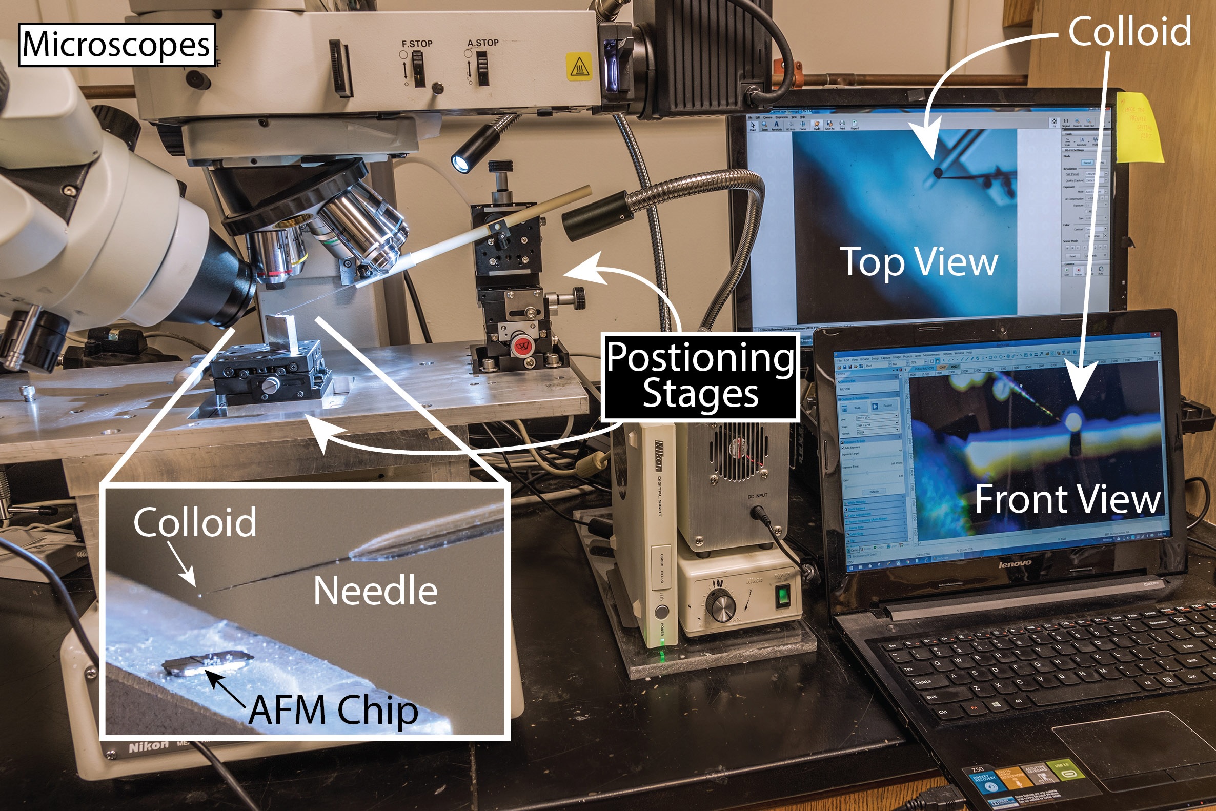 Figure 1. Setup for assembly of custom AFM colloidal probes. A high-resolution 3-axis manual positioning stage (the one on the right) controls an ultra-sharp (<1 μm) tungsten needle. The colloid (50 μm diameter alumina in this example) adheres to the tip of the needle with the help of electrostatic forces. The tipless AFM chip sits on a 2-axis manual stage (underneath the lens) for positioning in the field of view of the microscopes. The two microscopes provide a simultaneous top and front views of the process for control over positioning and approach, respectively.
Normal Force Calibration of Custom Probes
Although many methods exist to calibrate AFM cantilevers, most are unable to deal with ultra-high forces and are untraceable to absolute measurement standards. To address this problem, we designed a ‘direct calibration’ system (described in Figure 2) comprising an analytical microbalance and a piezo nanopositioning stage, both of which were pre-calibrated and are traceable to measurement standards. This setup is used to obtain the spring stiffness of our custom probes, which are then loaded into an AFM to calibrate the position sensing detector through indentation (Figure 3). In our collaborative paper with Drs. Khare and Carpick at the University of Pennsylvania, we demonstrated the ability to quantify forces up to 3.4 mN while easily resolving friction coefficients below μ = 0.01 for a steel colloid on single-crystal MoS
2 using a commercial AFM and cantilever. This is the largest measured normal force in an AFM-based measurement we are aware of and it exceeded our initial target by >3x.
 Figure 2. We developed a traceable system for direct normal stiffness calibration of AFM cantilevers using a precision analytical microbalance and a nanopositioning stage. (a) Schematic of the calibration setup; (b) close-up view of the contact between the AFM probe and the microbalance; (c) in-situ camera view of the approach to contact; (d) side-view of the silicon cantilever with a steel sphere mounted and loaded against the microbalance to obtain load-displacement relationships.
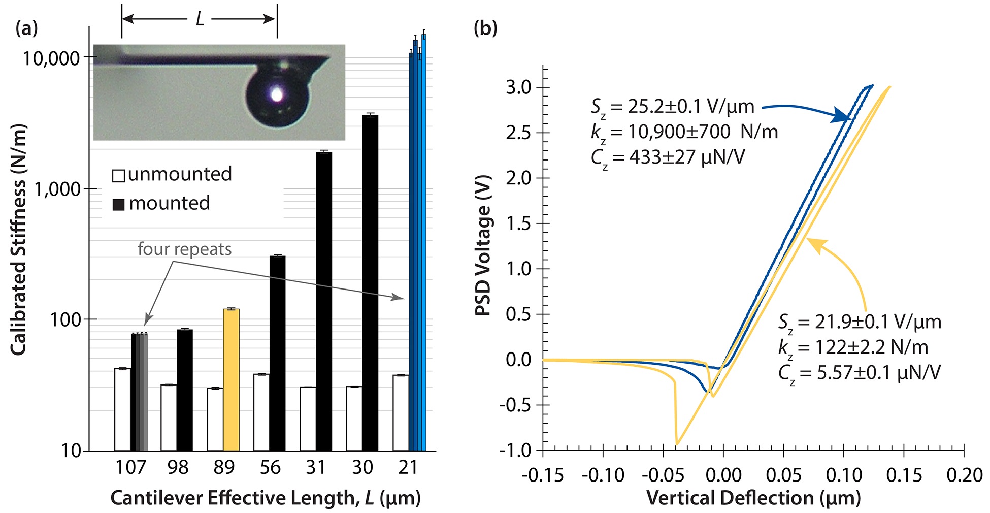 Figure 3. a) Stiffness of 7 mounted probes with various effective length (L); the unmounted cantilever stiffness, before a colloid was attached, is shown for reference. Using the stiffest probe, we achieved forces well above our 1 mN target using setpoint voltages well-below the limit (8 of 20 V) of a commercial AFM (Bruker Dimension V 3100). b) Raw signal voltage indentation curves for probes with colloids positioned 89 and 21 μm away from the fixed end of the cantilever. The approach and retract curves show substantial snap-in and snap-out due to adhesive forces. The smooth sloped part of the loading curve was used to quantify the AFM’s position sensing detector’s (PSD) sensitivity (S); the normal force calibration constant (Cz) is the ratio of the cantilever spring constant and the PSD sensitivity.
Lateral Force Calibration of New Probes
Figure 3. a) Stiffness of 7 mounted probes with various effective length (L); the unmounted cantilever stiffness, before a colloid was attached, is shown for reference. Using the stiffest probe, we achieved forces well above our 1 mN target using setpoint voltages well-below the limit (8 of 20 V) of a commercial AFM (Bruker Dimension V 3100). b) Raw signal voltage indentation curves for probes with colloids positioned 89 and 21 μm away from the fixed end of the cantilever. The approach and retract curves show substantial snap-in and snap-out due to adhesive forces. The smooth sloped part of the loading curve was used to quantify the AFM’s position sensing detector’s (PSD) sensitivity (S); the normal force calibration constant (Cz) is the ratio of the cantilever spring constant and the PSD sensitivity.
Lateral Force Calibration of New Probes
Absolute lateral forces are exceedingly difficult to quantify in the AFM and this is particularly true when applied to a wide range of cantilever stiffnesses and probe radii. To address the well-recognized problems of existing lateral force calibration methods, we adapted the well-subscribed reference lever method of normal force calibration to the problem of lateral force calibration. The method of retaining traceability is simple conceptually: (1) create a reference lever (a beam of fixed but unknown stiffness); (2) calibrate the lever with the direct calibration method, which is traceable to absolute measurement standards; (3) use the standard reference lever method in lateral mode to quantify the target cantilever spring constant and its uncertainty. The device, the methods we use to calibrate the device, and the methods we use to apply the calibrated device toward AFM lateral force calibration are illustrated in Figures 4 and 5. Our paper detailing the rationale of the approach, the details of the method, and the uncertainty analysis of the resulting forces is approaching the final stages of preparation.
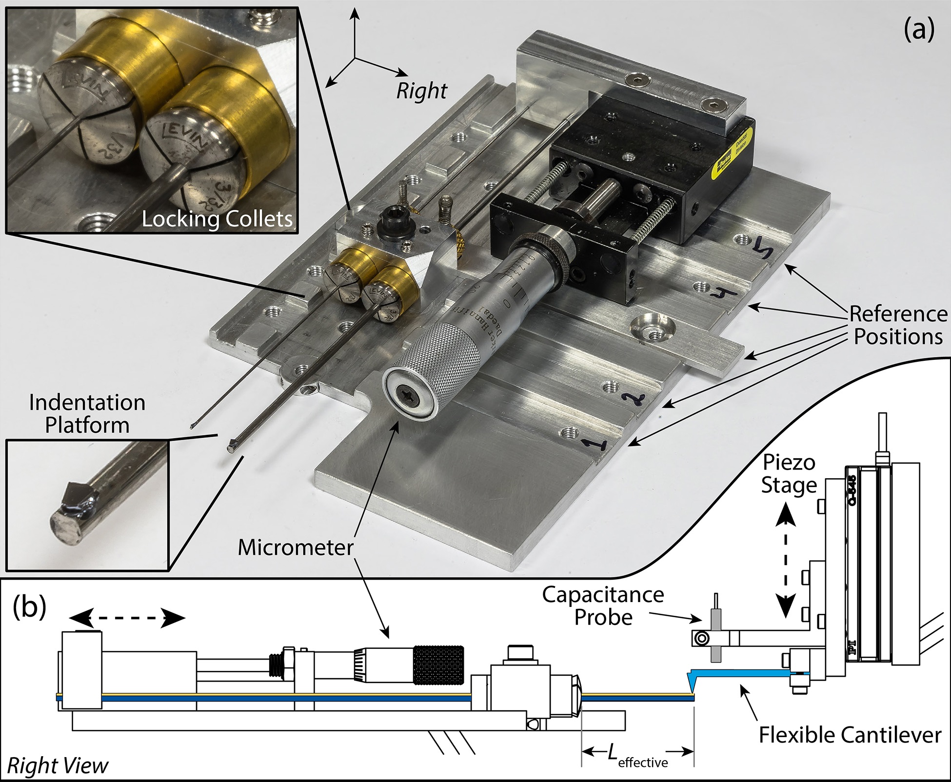 Figure 4. (a) Reference lever calibration device consisting of two steel beams with variable length. The micrometer stage controls the effective length of these beams, while the high-precision locking collets provide fixed support in all directions. To expand the scope of permissible beam lengths beyond the range of the micrometer, the locking collets can be placed at 5 different reference positions using the key (Position 3). When the device is placed in an AFM, the colloidal probes are loaded against one of the silicon indentation platforms glued at the ends of the beams. Direct calibration of the two reference levers follows a two-step process involving (1) direct calibration of a capacitance-probe-based indentation device with the methods described in Figure 2 and (2) indentation measurements to calibrate the reference lever calibration device (b).
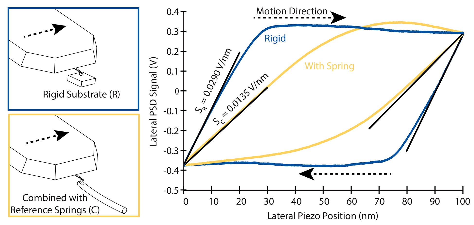 Figure 5. Use of the reference spring device to calibrate lateral forces of AFM cantilevers. First, we use the existing standard practice to obtain the lateral sensitivity; i.e. the AFM is loaded against a nominally rigid surface (top left) and the lateral sensitivity (V/nm) is obtained from the static portion of the friction loop (black line in the plot). The lateral sensitivity procedure is repeated against the calibrated lateral force reference spring (bottom left) to obtain the combined lateral sensitivity (one known reference spring and one unknown spring in series). The lateral stiffness of the unknown AFM cantilever is:
  . Using measured sensitivities (right) and the pre-calibrated reference spring stiffness (200 N/m), the calibrated AFM lateral stiffness of this cantilever is:
  and the lateral force calibration constant is:
  .
Microtribometry
.
Microtribometry
To close the measurement gap starting from the practical scale, we designed a new microtribometer which can replicate the conditions of an AFM test (Figure 6). Because traditional tribometry is also an inherently displacement-based measurement, the normal force sensitivity that can be achieved with a tribometer is only limited by the cantilever’s compliance. However, these are macroscale systems and probe mass must be reduced with spring rate to avoid excessive reductions in resonance frequency, which impedes detection of frictional dynamics and increases the noise floor. By systematically reducing the weight of the cantilever assembly and its compliance, we have achieved normal force sensitivities of ~1 μN and friction force sensitivities of ~200 nN, which is nearly 4 orders of magnitude below the maximum loads we have been able to achieve in the AFM.
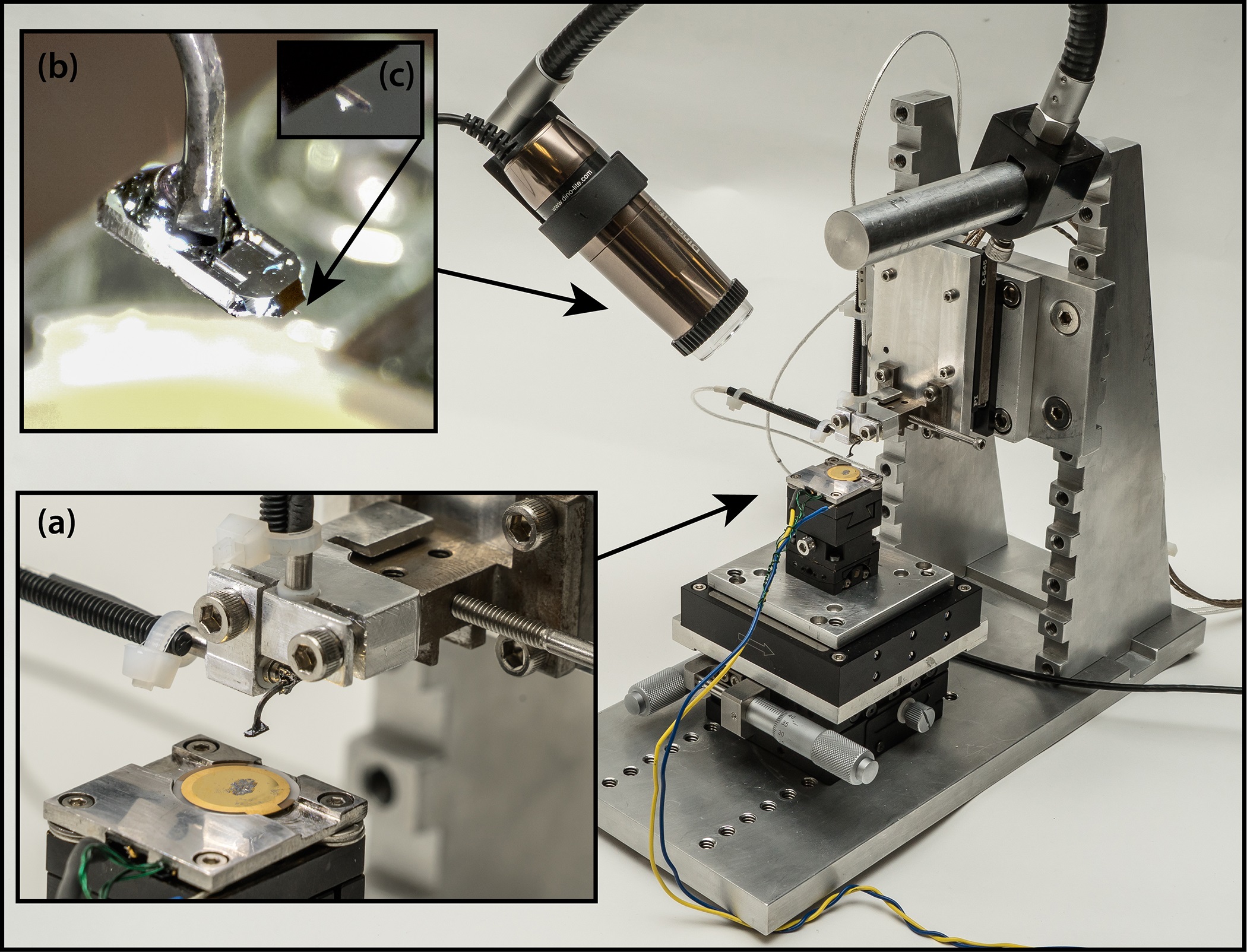 Figure 6. Custom microtribometer designed and fabricated for use in this project. This tribometer has been designed for speeds down to 100 nm/s and has achieved a friction force noise floor as low as 200 nN in the latest iteration. The normal and lateral actuation are provided by high-precision piezo positioning stages. (a) Zoom-in of the load cell with an AFM chip adhered to the tip of the flexible cantilever; capacitance probes are used to sense the deflection of the steel beam. The single-crystal MoS2 countersurface is adhered to the one of the electrodes of a quartz crystal microbalance (QCM), which we have begun to use in collaboration with Prof. Borovsky at St. Olaf College to study speed effects. (b) Live camera view of the AFM chip and probe. (c) Live camera view of custom probe comprising a 27 μm diameter colloid mounted to a commercial AFM cantilever.
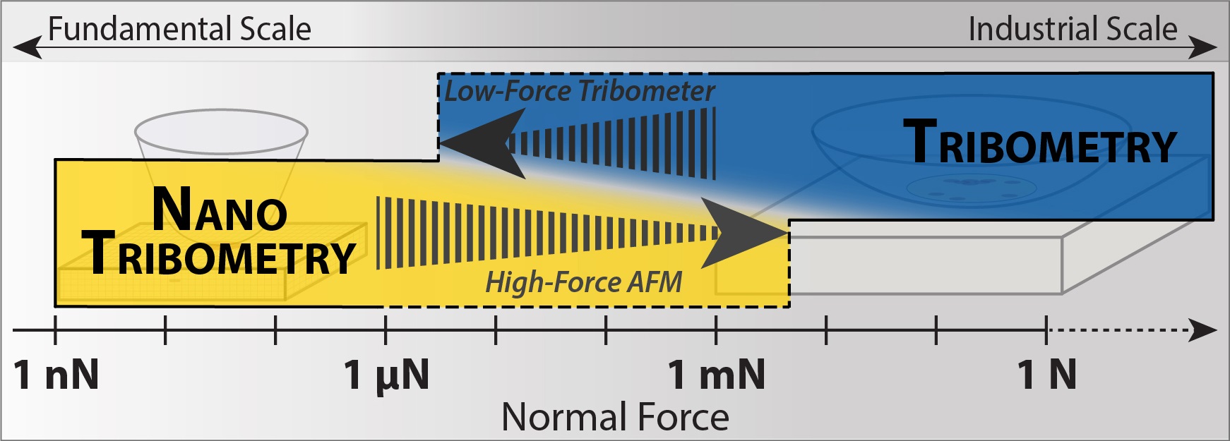 Figure 7. With existing capabilities, we can probe the exact same tribological interface and achieve the same load, speed, and track length conditions with any commercial AFM and our low-force tribometer, over a previously unexplored range (~4 orders of magnitude in load) of experimental conditions.
Summary and Outlook
Figure 7. With existing capabilities, we can probe the exact same tribological interface and achieve the same load, speed, and track length conditions with any commercial AFM and our low-force tribometer, over a previously unexplored range (~4 orders of magnitude in load) of experimental conditions.
Summary and Outlook
The field of tribology is currently divided between nanoscale and macroscale, fundamental and practical. As a result, what we have learned about the fundamental origins of friction has had limited impact in practice. This research provides an experimental toolkit that we and others can use to conduct the studies needed to elucidate how fundamental frictional phenomena manifest themselves in more practical tribological contacts. In the next phase of research, we will use these methods to map friction of single-crystal MoS
2, a model solid lubricant, and gold, a model metal, across this and other relatively unexplored measurement regimes. Many previous studies investigating tribological scaling from the nanoscale to more practical scales have approached the problem by probing the end-points. In almost all cases, nanoscale friction coefficients are many times smaller than their macroscale counterparts for reasons that remain unclear and untested; the most obvious explanation is the onset of additional contributors at the micro/macro-scale including plasticity, sub-surface damage, debris formation, and other third body effects. By continuously and traceably quantifying friction of well-controlled systems across this measurement gap, we anticipate elucidating where these differences first emerge; why they occur; whether they are dominated by differences in contact size, load, contact stresses, or sliding speed; and whether the trend of increased friction with size scale is an inherent feature of all or most tribological systems. Ultimately, we hope to offer guidance about how to use the fundamentals of friction for materials design and practical friction and wear control.
Acknowledgements
We thank Dr. Harman Khare and Dr. Robert Carpick for their collaboration on the development of high-force AFM methods and Dr. Borovsky for his collaboration on the variable speed aspects of the project. We also thank the Society of Tribologists and Lubrication Engineers; without the generous support provided by the E. Elmer Klaus fellowship, the most recent progress on this project would have been impossible.