A type of dynamic fluid seal known as a centrifugal fluid seal uses centrifugal forces generated at high rotary speeds in a bearing shaft to retain the sealing fluid.
Centrifugal magnetic fluid seals are an alternative type that operate effectively in low- and high-speed modes.
New centrifugal magnetic fluid seal designs have been developed.
Seals perform an important and at times overlooked function in a lubricant system. They prevent or minimize the movement of the lubricant between two surfaces and also minimize the level of contamination in the system.
Seals are divided into static and dynamic types. Static seals operate in systems where the mating surfaces do not move relative to each other. In contrast, dynamic seals operate under conditions where the mating surfaces are in relative motion with each other.
A previous TLT article discussed a second-generation engine oil seal prepared from polytetrafluoroethylene (
1). This seal represented an improvement over a first-generation material because it was installed without an installation aid. Performance testing showed the benefit of having a reduced length and more grooves in the seal lip. Evaluation testing demonstrated that additional grooves led to a reduction in friction in the engine.
One type of dynamic fluid seal is known as a centrifugal fluid seal. Dr. Leszek Matuszewski, lecturer in the ocean engineering and ship technology department at Gdansk University of Technology in Gdansk, Poland, says, “This seal employs centrifugal forces generated at high rotary speeds in a bearing shaft to retain the sealing fluid. The centrifugal forces pressurize the lubricant, forcing the lubricant out of the seal and back into the housing or the sump. As a result, the bearing components remain constantly lubricated as the shaft is rotating.”
While this dynamic fluid seal operates in a satisfactory manner at high rotary speeds, operational problems are detected at low speeds. Matuszewski says, “The conventional centrifugal seals employ the centrifugal forces at high rotary speeds to retain the sealing fluids. They work satisfactorily at high shaft speeds, while at lower speeds the sealing fluid is not kept in place and, in the static condition, the seal does not support any pressure at all. Other difficulties associated with conventional centrifugal seals include problems related to fluid leakage, limited lifetime due to the wear of the elastomer seal, high torque and high static friction due to the use of elastomeric auxiliary seals.”
An alternative to centrifugal fluid seals is known as centrifugal magnetic fluid seals (CMFS). Matuszewski says, “A CMFS gives a completely hermetic shaft seal at static, low- and high-speed modes, which enables increased seal lifetime, minimum torque and minimum static friction. Shaft contacts contain a magnetic fluid instead of a solid material in contrast to other types of seals.”
Even though magnetic fluid seals are used in important industrial applications in modern machinery and processing equipment, especially in gas and vacuum applications for high-speed rotating shafts, new design solutions are desirable to meet the growing demands for more efficient machinery that must operate over longer time periods at an optimum performance level.
New designs
As part of his research on (CMFS), Matuszewski had developed some new designs. He says, “A schematic of the basic design of a CMFS is shown in Figure 3. The magnetic flux lops, which are drawn as dotted lines, are created by a permanent magnet, a pair of magnet covers with several concentric projections and grooves, a pair of annular rings, a sleeve and the magnetic fluid injected into the gap. The covers protecting the magnet, the annual rings and the sleeve are made of ferromagnetic materials.”
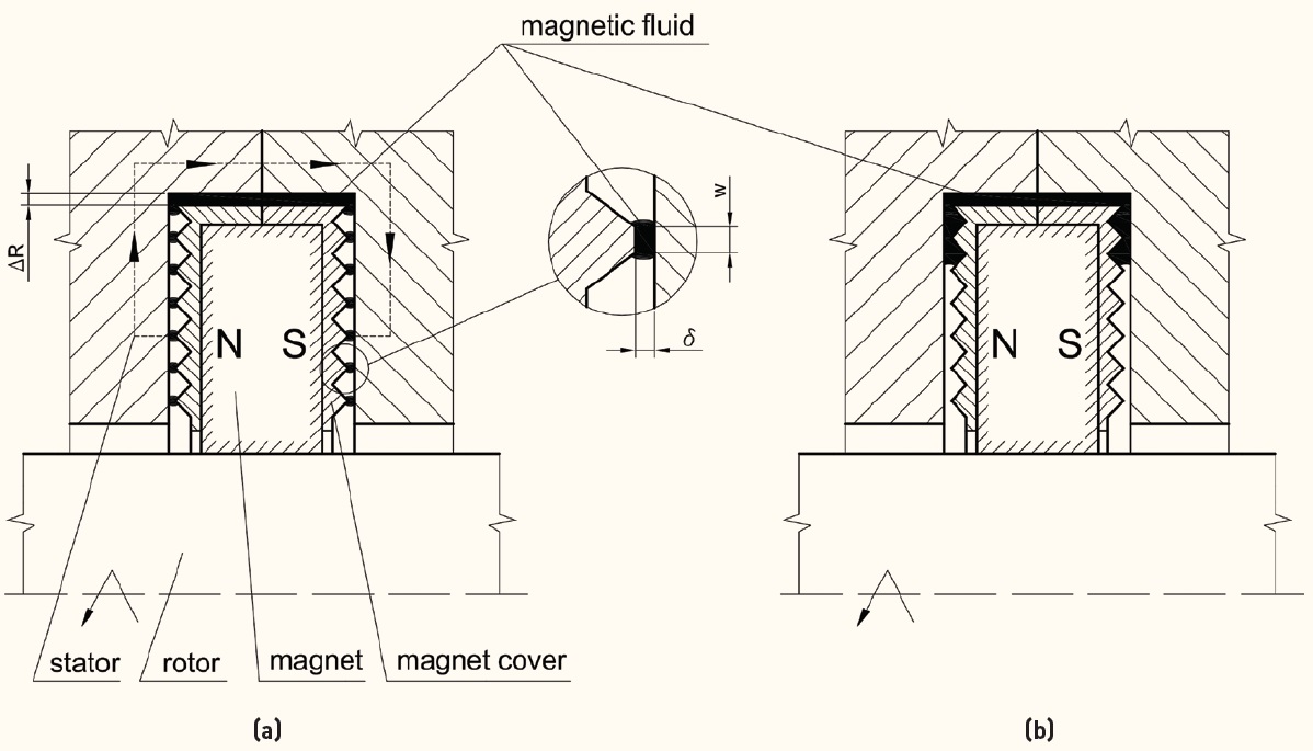 Figure 3. Two images of a centrifugal magnetic fluid seal are illustrated with (a) showing the position of the magnetic field at low rotating speed and (b) showing the position of the magnetic field at high rotating speed. (Figure courtesy of Gdansk University of Technology.)
Figure 3a shows the position of the magnetic field at low rotating speed while Figure 3b shows the position of the magnetic fluid at high rotating speed. Matuszewski says, “The sealing pressure is governed by magnetic attraction at low rotating speeds. When the ratio of the pressure caused by centrifugal force to the pressure produced by magnetic force exceeds one and the shaft rotating speed increases, the sealing pressure is generated by the centrifugal force.”
Matuszewski has developed centrifugal magnetic fluid seals using several designs. Included is a seal with a vee-shaped disc and a stationary magnetic system, a vee-shaped magnetic-centrifugal fluid seal and a centrifugal magnetic fluid seal with a stationary vane and a rotating magnetic system.
Matuszewski says, “The magnetic fluid can be applied in the same manner as other seals using techniques such as simmering or using O-rings. Another advantage for CMFS compared to centrifugal fluid seals is they can operate without any contact between rotating and fixed parts even under large rotating vibration because the gap in this seal can be kept very large. One other benefit is that CMFS can store the sealing fluid in the gap even when the rotating shaft is at rest.”
Matuszewski indicated that he will be evaluating new nanomagnetics in colloidal liquids and new projection shapes versus variable magnetic flux. Additional information on CMFS can be made by contacting Matuszewski at
leszek.matuszewski@pg.edu.pl.
REFERENCE
1.
Canter, N. (2005), “The possibilities of second-generation PTFE engine oil seal,” TLT,
61 (2), pp.12-13.