FDA benefits include early detection, better particle characterization, increased operational uptime, extended periods between scheduled repairs and decreased maintenance costs.
FDA’s main challenges are extracting the debris in a reliable, controlled manner and accurately interpreting the results.
While FDA makes sense for wind turbines, unique challenges remain, including the sheer enormity of the filter.
The cost of replacing certain wind turbine components is jaw dropping. Here are some stats for a five-megawatt (mw) wind turbine:
•
Blade: $391,000-$547,000
•
Blade bearing: $62,500-$78,200
•
Gearbox: $628,000
•
Generator: $314,000
•
Electronic modules: $16,000 (
1).
This is even more significant when you consider that the majority of the wind turbines are out of warranty.
Decades ago the aviation industry embraced filter debris analysis (FDA) as a reliable means of determining the condition of aircraft. It just makes sense that this technology would be just as valuable for wind turbines. Both pieces of machinery incorporate expensive parts that need to work reliably in often extreme conditions. The difference is that aircraft are easier to maintain than wind turbines.
Allison M. Toms, subject matter expert (SME) for GasTOPS Inc. and a member of the STLE board of directors, says, “Recent studies on aviation bearings and gearboxes (900,000-plus samples) have shown that traditional oil analysis provides limited and sometimes no warning on failure progression or faults, even with frequent sampling of 1-10 flight hours. The burden of frequent sampling with limited success is a concern due to manpower, costly maintenance and potentially complete loss of the aircraft.”
Toms adds: “In the aviation industry, FDA has been shown to be overwhelmingly successful for advanced fault identification and early failure warning—often greater than 100 flight hours when other monitoring techniques had no indication of any abnormality. Applications utilizing this technology have seen considerable successes including early warning on catastrophic failure, increased operational uptime, extended periods between scheduled repair and decreased maintenance costs.”
FDA
With the trend toward finer filtration, more debris is captured in filters and less remains in the oil. Given this, 95% of the wear debris that could provide useful insight into machinery condition is caught in the filter and never ends up in an oil sample (
2).
While filters are designed to keep increasingly smaller particles from damaging parts, the downside is that they also hide component wear from traditional fluid analysis.
Sometimes just inspecting a used oil filter will point to the onset of a serious issue, but more often than not the oil filter needs to be sent to a lab and tested.
Dr. John K. Duchowski, corporate director R&D Filtration for HYDAC, an STLE Fellow and holder of the society’s CLS and OMA I & II certifications, says, “Regardless of which system it is employed in, the filter element can provide a wealth of diagnostic information about the workings of a system. In contrast to a fluid sample, which represents a slice in time and space, the filter element collects a wealth of historical diagnostic information that has been accumulated over the entire service life interval. In many cases, through careful analysis, it is even possible to recover information about an earlier upset that had already come and gone and would not necessarily show up in an oil sample collected outside of that timeframe.”
FDA in aviation (3)
FDA was first widely employed in the aviation industry because leaders recognized the filter is a rich source of information about the health of oil-wetted components in aircraft machinery. A program developed by Air Research in the 1980s claimed a 95% success rate for predicting catastrophic failures (
4).
In the mid 1980s, the Canadian Forces’ Sea King helicopter was plagued with main gearbox debris problems. The Canadian Defense Research Establishment Atlantic (DREA) embarked on a research project to determine if the debris from the filters could be used to reliably evaluate the condition of helicopter gearboxes. The project was so successful that FDA became an integral part of the maintenance program to determine the health of the Sea King gearbox.
The Sea King senior aircraft maintenance then asked the health monitoring contractor to work with DREA to develop the FDA program into an automated tool for mechanics at the flight line. The outcome of the project was the development and production of the FilterCHECKTM 200.
This instrument was simple to operate and in 15 minutes could efficiently clean a filter, quantitatively count and size the ferrous and non-ferrous debris via the inline particle debris monitor and prepare a patch of the debris for SEMEDX analysis. The instrument’s system accurately and repeatedly determined gearbox serviceability. The patch, however, still had to be sent to an expert analyst for metallurgical analysis, and this continued to be a lengthy process (
see Figure 1).
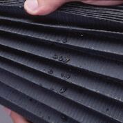 Figure 1. Wear debris on media. This indicates system component wear. A lab can identify the debris. (Figure courtesy of Baldwin Filter/Parker Hannifin Filtration Group.)
The U.S. military’s Joint Oil Analysis Program Technical Support Center (JOAP-TSC) in Pensacola, Fla., conducted testing of the FilterCHECKTM 200 and was impressed with its capabilities. However, JOAP wanted comprehensive first-line capability in a single, transportable instrument that included metallurgical analysis.
In 1999 JOAP initiated an application project to develop and include an energy dispersive X-ray fluorescence (EDXRF) capability in the FilterCHECKTM 200 unit.
Under the USAF productivity, reliability, availability and maintainability (PRAM) program, an alpha prototype and six beta prototype units were constructed that incorporated a miniature EDXRF system into FilterCHECKTM.
As a result of the JOAP-TSC PRAM project, the FilterCHECKTM 300 unit cleans the filter, counts and sizes the ferrous and non-ferrous particles, prepares a thin film patch of wear debris and determines the metallic composition and debris mass. The project went from prototype to production in one year.
“Today the aviation industry primarily tests engines/gearboxes for wear debris that can be analyzed by online or offline techniques,” Toms explains. “Modern gas turbine engines, commercial and military, are designed with inline ferrous and non-ferrous wear debris sensors. These sensors provide near-real-time analysis on bearing and gear health. When a wear/fault situation occurs, these sensors can diagnose and monitor them from progression of the first spall through providing prognostics for time-to-failure based on the specific component configuration.”
Toms continues, “When online sensors are not available, other techniques can be utilized. Most aircraft have magnetic chip detectors (MCD) placed in the oil stream. These devices collect primarily ferrous debris. Efficiency of the MCD depends on placement in the oil flow. This captured debris is removed from the MCD and analyzed either at the flight line or in a laboratory. Each individual particle can be analyzed as to its specific alloy and size, thus pinpointing the specific component wearing.”
Wind turbines
“Generally the only difference between oil filters for aircraft and wind turbines is the filter element geometry,” Duchowski explains. “It is possible to employ exactly the same filtration technology for helicopters, wind turbines, gas and steam turbines and paper machines; the main differences being dictated by the rigors of the application.
“For example, we do offer application-specific filter element design,” Duchowski adds. “In very practical terms, we recognize that gas turbine lubricating systems operate with relatively low viscosity oils at moderate temperature and, being generally clean, are relatively well stabilized. In contrast, wind turbine gearboxes operate with very high viscosity oils and under a very broad temperature range with much higher contaminant levels.”
The wind industry is still challenged by premature turbine subsystem/component failures (primarily gearboxes). This is especially true for turbines rated above 1 mw. The significant expense involved goes beyond just the cost of the failed components themselves to include the cost of the replacement procedure—a crane is usually required.
Offline and online condition monitoring have been of some help in preventing and delaying component failures, as have improvements in the formulation of gearbox oil.
Base stock
High-performance synthetic oils are becoming the norm for wind turbines—most newly installed turbines tend to be filled with them. Compared to mineral-based oils, synthetic oils have better thermal stability, lower pour points and higher viscosity indices.
The most prevalent synthetic base stock for wind turbine gearboxes is polyalphaolefin (PAO). PAOs are synthetic oils with a straight hydrocarbon chain that has an unsaturated carbon at one end of the chain. They have a VI between 140 and 180. Another synthetic base stock prevalent in wind turbines is polyalkyleneglycol (PAG). PAGs have a higher VI than PAOs—between 180 and 260. However, PAGs have challenges in paint and elastomer compatibility.
Additives
For wind turbines, the most common types of additives are antiwear (AW) and extreme-pressure (EP) additives. These types of additives are active during mixed friction lubrication, forming a reaction layer to reduce direct metal-to-metal contact. AW additives are effective for moderate loading and temperature; EP additives are effective under high loading.
Michael Blumenfeld, research associate, ExxonMobil Research and Engineering Co., says, “Wind turbine gearbox lubricants have to protect gear and bearing components by carrying incredibly high loads under severe conditions such as extreme temperatures. As a result, lubricant formulators must balance a broad array of performance areas while ensuring the product delivers the longest oil drain intervals possible." To add to the challenge, these fluids must be able to simultaneously protect high-speed and low-speed components because wind turbine gearboxes have multiple stages with large gear ratios. This is particularly difficult to achieve with a single fluid, since low-speed and high-speed applications typically require very different viscosities and only the most advanced fluids are up to the challenge.
He continues, “Further, wind turbine gearbox lubricants need to be compatible with the broad array of metals, polymers and coatings that are used by gearbox manufacturers and must be formulated with suitable performance reserve to accommodate the rapid change and advancement in wind turbine technology (
see Figure 2). It is important that the lubricant can deliver in all of these areas, as the cost of downtime is massive. Remote locations, tight spaces and working at heights make changing the gearbox lubricant an expensive logistical challenge to be avoided if at all possible (
see The Evolution of Lubrication Oil for Wind Turbines).”
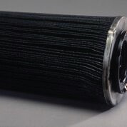 Figure 2. Gel-like coating on media. This indicates certain oil additives may have trapped water. (Figure courtesy of Baldwin Filter/Parker Hannifin Filtration Group.)
The evolution of lubrication oil for wind turbines
In the following, Michael Blumenfeld, research associate, ExxonMobil Research and Engineering Co., explains how lubrication for wind turbines has evolved.
Thirty years ago it would have been very challenging to find a lubricant that was designed specifically for wind turbine gearboxes. The application was not established enough, turbines were small, and the challenges of the wind industry were not yet fully appreciated. During these early days, general lubricant technology was repurposed from industrial gear and circulating applications.
It wasn’t until the 1990s, with the development of megawatt-class turbines and the identification of micropitting as a key concern for wind turbine gears, that the industry recognized the unique challenges of lubricating a wind turbine gearbox. This led to the development of oils specifically made for wind applications, such as our own Mobilgear SHC XMP 320. These wind turbine lubricants were designed with the most advanced technology available, and they balanced the need for extreme load carrying with a fluid that could operate over wide operating conditions ranging from small onshore turbines to large offshore turbines.
Two of the biggest areas of advancement in wind turbine gearbox lubricants have been in the areas of improved viscosity index and oil drain interval. The massive growth in wind capacity has spurred the lubricant industry to develop new synthetic base stocks that are tailor-made for wind turbine gearbox applications.
These metallocene-catalyzed PAO (mPAO) base stocks possess a very high viscosity index, which means they maintain viscosity over a broad range of operating conditions, from low temperature start-up to operating temperature of up to 80 C (176 F). They have been engineered to address the dual challenge of providing efficient cold-starts and high elastohydrodynamic lubrication film thickness under load. Additionally these mPAO base stocks are stable under mechanical, oxidative and hydrolytic stresses, which means the oil lasts longer and oil changes are required less often. In the future, lubricant manufacturers will use these mPAO fluids to provide additional energy efficiency benefits by lowering viscosity without impacting equipment durability.
Even more recently, the lubricant industry has addressed the lubricant-related causes of white etch cracking (WEC) failures in wind turbine gearbox bearings. Although there are several risk factors contributing to WEC, the gearbox lubricant has an important role to play in mitigating one of the causes of these failures. Laboratory tests have shown that lubricant additives that contain metals such as calcium, zinc and molybdenum can interact with dissolved water in the lubricant to accelerate damage in bearings susceptible to WEC. Some lubricants formulated with metal-containing additives are hygroscopic and hold a large amount of water.
It appears that these additives (and their affinity for water) play a role in delivering elemental hydrogen to the bearing surface. However, metal-free lubricants do not promote WEC damage. By formulating without these metal-containing additives and keeping dissolved water levels low, modern lubricant formulators have made an important contribution to reducing the prevalence of WEC and improving turbine reliability.
 © Can Stock Photo / eyematrix
Wind turbines condition monitoring
Mindy Villalba, project manager, SGS North America (formerly Herguth Laboratories, Inc.), says, “Typical oil condition monitoring practices in the wind industry include a periodic review of the main turbine gearbox oil and the system hydraulic oil for basic property analysis, degradation contamination and wear. Much of the oil sampling and testing is performed not only to verify condition of both the oil and equipment but also to satisfy the requirements of the system warranty. Approximately 75% of our customers sample and test the oil every six months. The remaining 25% of our customers review the oil on a more frequent basis, at least every three months.”
Condition monitoring has become a standard solution in modern wind turbines via traditional offline monitoring, online monitoring with sensors or a combination of both. Typical condition monitoring for wind turbines includes:
•
Offline oil sample six-month intervals
•
Inline or online oil debris monitoring
•
Oil cleanliness level measurements
•
And increasingly FDA.
Offline monitoring requires oil sampling, which can be difficult—especially with offshore wind turbines. However, this can still be a very valuable method for gauging the condition of the oil. Typical oil sample tests for wind turbines include:
•
Water content
•
Sediment and insolubles
•
Acid number
•
Base number
•
Kinematic viscosity
•
Wear, contaminant, additive elements (including metals)
•
Particle count
•
Oxidation condition
•
Low temp Brookfield viscosity (
5).
Online monitoring requires permanently installed sensor systems that provide continuous wear debris fault detection, oil depletion and degradation information. The main benefit is continuous measurement, but it is costlier, and there is concern about the accuracy of the fluid condition sensors.
STLE-member Arthur Miller, condition monitoring specialist and SME for Lubricants, EDF Renewables, explains, “First and foremost, we in the wind industry are bound by minimum requirements set forth by the turbine manufacturer’s service manual. This means the lab analysis followed by many is generic and not as intuitive as it could or should be and is only drawn every 12 months. The tests generally performed will give some insight into the condition and health of the oil but not so much for the condition of the equipment.”
He adds, “Since spectroscopy has limitations with the size of the particles captured, which is the primary method for collecting and quantifying the various elements including the wear metals, we miss most of the information contained in the samples. This is because the particles aspirated are less than 15 μm in size and actually average about 5-7 μm. The gearbox oil filters are designed by the OEMs of the gearbox to filter down to roughly 10 μm, which captures the useful debris. For this reason, the analysis of the filter should be included in the usually scheduled maintenance, but it typically is not due to cost and competiveness.”
Regarding main filtration loop filter element analysis, Miller explains, “This is an expensive addition to the regularly scheduled sample cycle prescribed by the OEM manual, thus preventing its acceptance industry wide. There is perceived value in this level of analysis, but I don’t think the current methods are consistently informative. If there becomes a cost-effective method for extracting the wear debris from the whole of the filter element, which is about 13 feet long when unraveled, then perhaps more of us will be willing to move in that direction.”
“Removing the main filtration loop filter for debris analysis can be daunting for both maintenance and laboratory personnel alike,” Villalba adds. “There is much time and labor involved for technicians to remove and replace the main filter. Once the filter has been collected, it is large and cumbersome to test in the laboratory. The filter analysis testing process is relatively expensive, considering the low cost for routine oil analysis. There is no doubt that the industry would be open to testing the filtration loop filter element, but the cost for testing and the labor for maintenance must attain a better balance for this practice to become routine (
see Figures 3 and 4).”
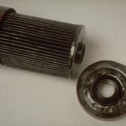 Figure 3. Media covered with thick, loosely held sludge. This indicates an excessive amount of fuel soot. This can be the result of a wide range of factors. An experienced engineer can identify the root cause of the problem. (Figure courtesy of Baldwin Filter/Parker Hannifin Filtration Group.)
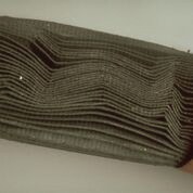 Figure 4. Wavy media pleats, deteriorated outer wrap or sticky, shiny, tightly held sludge. This indicates moisture present in the system. (Figure courtesy of Baldwin Filter/Parker Hannifin Filtration Group.)
Miller believes that the wind industry should move away from the usually prescribed oil analysis for trending the gearbox health and reserve oil analysis for monitoring the health of the gear oil. The gearbox could be monitored in part by performing a complete analysis of the main filter element; alternatively, oil debris monitoring sensors could be installed, which Miller agrees can spot internal gearbox wear early.
FDA and wind turbines
FDA is a critical investigational step, but due to these logistical issues with wind turbines, it is usually practiced only after catastrophic equipment failure. “However, filter analysis also can provide very useful data regarding premature wear,” Villalba says. “Just as oil samples are screened for evidence of equipment wear, so too can filters be analyzed for similar information. Because the filters typically remove large particles, analysis of the debris can be helpful in determining premature or abnormal wear conditions. In this manner, filter analysis can provide a way to incorporate predictive maintenance into reliable practices.”
FDA has been used by some industries for decades, but it has not yet been fully embraced by the wind energy industry. In most cases, the filter is discarded during routine maintenance and a very valuable piece of the condition picture is lost. The filter traps important wear information that may not be collected for standard oil analysis. And, as mentioned earlier, today’s finer filters tend to hold more debris than previous iterations, meaning there is less and less material for traditional oil analysis to process.
By examining wear debris particles, labs can use several techniques such as SEM to provide fast, automated wear particle counting and classification by elemental composition (
6).
One reason that FDA tends to be more accurate than standard oil analysis for wind turbines is the following: It takes about 20 minutes to climb the wind turbine tower and sample the oil after the turbine stops. This means it is nearly impossible to get a warm, representative sample of oil from a wind turbine. Samples collected on cold, settled oil, from any source, will not have a representative particle distribution.
Compact filters
Most commercial wind turbines have large gearbox oil filters, typically 15-30 inches (400-800 mm) tall and weighing 10-20 lbs. (4-9 kg). Because of the filter’s sheer size, the expense of logistics and analysis are barriers to FDA. One solution is a compact filter. Logistics and analysis costs for the compact filter are much lower than a standard filter.
Field tests were conducted on nine-mw wind turbines from July 2015 to December 2016. Analysis demonstrated accurate SEM particle identification for the main and compact filters. The trial also showed that compact filters lead to more consistent sample preparation (
7).
“National Renewable Energy Laboratory (NREL) has presented its compact filter data study at various wind turbine and tribology conferences over the past couple of years,” Villalba says. “The data proved that integrating the compact filter into the main loop system is a great way to capture and evaluate trend-able filter analysis. Utilizing scanning electron microscopy (SEM), we were able to characterize the particulate for both size and composition. The ability to identify all captured particulate, including non-ferrous particles and contaminants, allows for an in-depth evaluation of potential wear and failure modes. The process also was productionized, such that a much customized SEM technique could become a more affordable and trend-able testing option.”
She adds, “The three main challenges we see with current filter testing practices are cost, logistics and trend-able techniques. The compact filter analysis study by NREL showed that all three challenges could be tackled concurrently. The compact filter proved to be easier to access for maintenance personnel, and the compact filter was very easily handled in the laboratory.
“Because the logistics of removal and handling of the compact filters greatly improved the overall process, the cost of maintenance and testing naturally decreased as well,” Villalba says. “People involved in the wind power industry need to know that compact filter integration is an available course of action.”
Other technologies
“The primary manner in which the emerging technologies, like the Internet of Things, will impact filtration technologies is allowing for acquisition, storage, manipulation and evaluation of very large data sets with a large number of variables,” Duchowski says, “At the moment, not much information is being logged on the state and the health of the system. In addition, the ability to combine signals from the differential pressure sensors, water content or relative humidity sensors, particle counters and others would open entirely new avenues to system observation and maintenance (
see Figure 5).”
 Figure 5. Deformed canister or gasket blowout. This indicates excessive oil system pressure, which is typically caused by a stuck or malfunctioning oil pressure regulator valve in the oil pump assembly. This problem should not be attributed to the filter. (Figure courtesy of Baldwin Filter/Parker Hannifin Filtration Group.)
Regarding online particle counters, Blumenfeld says, “They have become a common addition to the condition monitoring portfolio of wind turbine fleets. However, many of these online systems count antifoam additives (which are designed to be insoluble soft droplets in the oil) as particles, so they cannot provide an absolute measure of the quantity of damaging hard particles entrained within a lubricant.”
He continues, “When an accurate particle count is required, optical particle counting must be used to eliminate interference from soft materials such as antifoam. We have recently seen cases where operators mistake online particle counters for absolute measurements of hard particles. This leads to elevated particle counts and operators may then try to aggressively pre-filter their lubricant even though it is perfectly clean and does not contain hard, damaging particles. The customer ends up expending significant resources removing a beneficial lubricant additive and, in the process, reducing the performance and longevity of their lubricant.”
Final thoughts
Traditional oil condition monitoring and continuous monitoring through sensors tells a big part of the picture but not everything. For all machinery and especially expensive machinery like wind turbines, the cost of condition monitoring, pales in comparison to the cost of damaged and destroyed components that render the machinery inoperative. With the pore size of oil filters trending smaller, FDA may be a very important piece of the condition puzzle.
“As has been the case for decades, power densities of wind turbine gearboxes continue to increase as OEMs seek to draw more power from existing platforms,” Blumenfeld says. “As power densities rise, we are continually learning about new wear mechanisms that impact wind turbine gearbox reliability. In parallel, the lubricants industry is inventing new chemistries that provide improved performance as we push the limits on what is possible in torque transmission. In the future, formulators of wind turbine gearbox lubricants will continue to respond quickly to these challenges so the wind industry can concentrate on generating power in a safe, reliable and economical fashion. The best way for this to happen is through continued dialogue and cooperation between lubricant developers and equipment builders.”
Finally, based on experience in the aviation industry, this is the advice that Toms has for the wind turbine industry: “Analyze as many filters as possible for a comprehensive component profiling of failure modes. If the wind industry starts utilizing compact ‘pre-filters,’ performing automated filter analysis will be a simple, reproducible means to achieve a comprehensive component health analysis.”
REFERENCES
1.
From Wind Turbine Gearbox Oil Filtration and Condition Monitoring. Shuangwen (Shawn) Sheng, NREL. Presented at the STLE Tribology Frontiers Conference, Oct. 25, 2015, Denver. Available
here.
2.
From Filter Debris Analysis, TestOil. Available
here.
3.
Material in this section not otherwise footnoted is from
Using Filter Debris Analysis to Identify Component Wear In Industrial Applications by Allison M. Toms and Michael P. Barrett. Available
here.
4.
From Understanding Oil Filter Debris Analysis; Reliable Plant. Available
here.
5.
Brookfield viscosity refers to a viscosity measurement performed with a Brookfield Viscometer. The viscometer motor rotates the spindle at a defined speed (measured in rpms) or shear rate; the viscometer measures the resistance to rotation and reports a viscosity value.
6.
D7919 Standard Guide for Filter Debris Analysis (FDA) Using Manual or Automated Processes. Available for purchase
here.
7.
Portions from
Wind Turbines: Improving the analysis of gear-oil debris with a compact filter, by Paul Dvorak, April 27, 2017. This article is part of Windpower Engineering & Development’s April 2017 issue. Available
here.