Just as with traditional brakes, tribology and friction reduction play an important role in regenerative brakes.
SAE is developing tests that gauge the blended performance of traditional and regenerative brakes.
Regenerative brakes have been around since 1902, going through several iterations until their first practical application in automobiles in 1997.
The following are facts:
1.
All objects that have both mass and velocity have kinetic energy.
2.
All moving vehicles have kinetic energy.
3.
The heavier the vehicle and the faster it moves, the more kinetic energy it has.
4.
The only way to stop a vehicle is to cut off the kinetic energy.
5.
When brakes are applied, kinetic energy becomes heat.
In a traditional braking system, that heat can be phenomenal—as high as 1,000 C (1,832 F) in Formula 1 race cars (
1). It is a waste of energy that could be used to power the car instead. This is where regenerative brakes come in.
The basic braking system
Traditional brakes—also called
frictional brakes or
foundation brakes—work similarly in most vehicles. The traditional brake in automobiles is usually hydraulic. They use hydraulic fluid to transfer pressure from the brake pedal to the brake shoe to stop the vehicle (
see Figure 1). Most cars have more than one type of traditional brake:
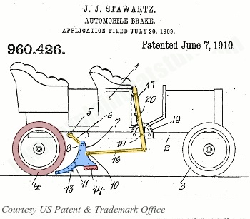 Figure 1. Early car brakes were Flintstone-ian. In 1910 John Stawartz invented a simple friction braking system. When the (yellow) brake lever is pulled, a giant (blue) brake shoe drops down under the back wheel (brown). As the car drives onto the shoe, the shoe’s (red) teeth bite into the road and the car comes shuddering to a halt. (Figure courtesy of U.S. Patent 960,426: Automobile Brake by John Stawartz, courtesy of U.S. Patent and Trademark Office and www.explainthatstuff.com.)
The disc brake.
Figure 1. Early car brakes were Flintstone-ian. In 1910 John Stawartz invented a simple friction braking system. When the (yellow) brake lever is pulled, a giant (blue) brake shoe drops down under the back wheel (brown). As the car drives onto the shoe, the shoe’s (red) teeth bite into the road and the car comes shuddering to a halt. (Figure courtesy of U.S. Patent 960,426: Automobile Brake by John Stawartz, courtesy of U.S. Patent and Trademark Office and www.explainthatstuff.com.)
The disc brake. It works by causing a pad to press against the brake disc. STLE Life Member Dr. Simon C. Tung, senior consultant, Innovation Technology Consulting, Inc., explains, “Disc brakes are typically located on the front two wheels. A caliper straddles a disc, and the disc turns with the wheel. Small hydraulic pistons in the caliper operate via pressure from the master cylinder. Friction pads clamp against the disc once the small hydraulic pistons apply the pressure, which slows down the disc and the wheel.
“The pistons only move a small distance to apply the brakes and, when released, the friction pads barely clear the disc since they have no return springs,” Tung adds. “The small gap is maintained by allowing the pistons to slip forward gradually as the pads become worn down. Rubber sealing rings around the pistons make this possible, preventing constant brake adjustment. Modern cars implement wear sensors to indicate when pads need replacement.”
The drum brake. These brakes are becoming less common in passenger cars, as their only real advantage over disc brakes is that they are less expensive to produce. When a car does have drum brakes, they are almost always in the rear wheels.
Tung explains, “A hollow drum turns with the wheel. A stationary back plate covers the open back of the drum. The back plate has two curved brake shoes carrying friction linings. Hydraulic pressure provided by pistons in the brake forces the shoes outward, causing the linings to press against the inside drum and, in turn, make the wheel slow down or stop completely. As opposed to disc brakes, return springs are used to pull the brake shoes back when the brake is released. Drum brakes tend to fade if applied repeatedly in a short time—they heat up and lose their efficiency until the heat dissipates.”
The handbrake. This works by applying the two rear brakes in a less forceful (and less effective) way. Its function is mainly to hold the vehicle stationary on a slope.
The hydraulic brake circuit consists of a fluid-filled master cylinder that connects to a separate slave cylinder. The brake pedal connects to the master cylinder. When applied, the brake pedal depresses the piston in the master cylinder, forcing fluid through connected pipes. The fluid reaches the slave cylinders at each wheel, which forces the piston to apply the brakes.
The surface area of the combined slave pistons, where the brake pedal force is applied, is greater than that of the master-cylinder piston. Hence, the master piston has to travel significantly farther to move the slave pistons than slave pistons travel to apply the brakes. This allows for the exertion of a large force by the brakes.
In order to prevent the rear brakes from locking and skidding, they are less powerful than the front brakes. However, in the past a load-sensitive pressure-limiting valve prevented locking in most cars by controlling spikes in hydraulic pressure. Limiting valves were replaced mainly by antilock brake systems and electronic brake proportioning that monitors wheel slip, especially in the rear axle.
A servo unit, using the pressure difference between the partial vacuum in the inlet manifold and the outside air, provides braking assistance by using a pipe connection to the inlet manifold. The servo is fitted between the master cylinder and the brake pedal. When the driver applies the brake pedal, it applies pressure to the master-cylinder piston and a set of air valves.
A large diaphragm connects to a master-cylinder piston. Prior to applying the brake, both sides of the diaphragm are exposed to the vacuum from the manifold. Applying the brakes closes the valves that link the rear side of the diaphragm to the manifold and opens a valve to let in outside air. The air’s high pressure pushes the diaphragm forward against the master-cylinder piston to assist braking. If the brake pedal remains depressed, the air valve stops drawing on the outside air, keeping brake pressure constant (
2).
Regenerative brakes
Regenerative brakes work differently (
see The History of Regenerative Brakes near the end of this article). As the driver steps on the brake, the electric motor runs in reverse. This slows the vehicle and also generates electricity that is stored in the battery and can be reused; this energy would otherwise be dissipated as heat. Nearly all electric and hybrid vehicles also have a traditional braking system that acts as a failsafe. This is especially applicable to vehicles covered by Federal Motor Vehicle Safety Standards (FMVSS) regulations (105 and 135 for brakes and 126 for electronic stability control).
Onboard electronics determine when to use the traditional brake system and when to put the motor into reverse. The system gauges the driver’s pressure on the pedal. A slight reduction in the car’s momentum activates the regenerative brakes and reverses the motor. If the pressure on the pedal is sudden and significant, the traditional brake is engaged.
Regenerative brakes work best with stop-and-go driving, where the energy lost due to heat would otherwise be about 80%. These brakes can recapture half that lost energy and improve fuel efficiency between 10% and 25% (
see Figure 2). Generally the heavier the vehicle and the faster it moves, the more energy regenerative brakes will send to the battery. The reason regenerative brakes don’t capture all that energy is that they work in tandem with traditional brakes.
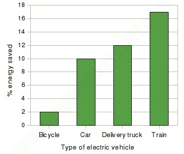 Figure 2. Energy saved, by percentage, using regenerative brakes. (Figure courtesy of www.explainthatstuff.com.)
In addition to improving the energy efficiency of the vehicle, regenerative brakes extend the life of the braking system—less stress on parts, which don’t wear out as quickly (
see Figure 3).
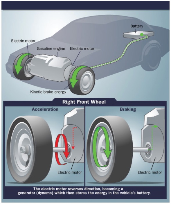 Figure 3. How regenerative brakes work. (Figure courtesy of How Stuff Works.)
While regenerative brakes do not create a tribolayer, traditional brakes will continue to create it in the presence of a regenerative system.
Dr. Mark Phipps, director of engineering for Bosch Brake Components LLC, says, “There will be a tribolayer (referred to the third-body layer or transfer layer in our industry) developed but only for the conventional brakes within the regenerative braking systems. We design the friction formulations with specific chemicals to generate the layer and provide the friction, noise and wear performance.
“However, this layer is quite dynamic in nature, in terms of its thickness and composition,” Phipps adds. “With how the brakes are being used on a regenerative system, I would expect that the layer would be different from a traditional brake system even when using the same friction couple. If the third body is not developed I would expect the noise and wear performance to be an issue for the customer.”
Braking systems work together
Despite the fact that traditional braking systems waste kinetic energy, regenerative brakes need traditional brakes. The current generation of regenerative brakes was never intended to be the sole means of stopping a car. They must be used with friction-based traditional brakes.
The regenerative braking effect diminishes at lower speeds and is not capable of quickly bringing a vehicle to a complete stop. Also, current regenerative brakes cannot immobilize a stationary vehicle on a hill; this requires physical locking.
Automobiles that do not have drive motors on all wheels (two-wheel drive) cannot take advantage of regenerative braking, since it only works with wheels that have motors. Obviously, for safety purposes, all wheels need the ability to brake.
Tung explains, “The electronic circuitry and the car’s onboard computer determine when to use the conventional frictional brake system or whether to put the motor into reverse. A slight reduction in the car’s momentum, determined by the driver’s force on the pedal, causes the vehicle’s electronics to activate the regenerative brakes and place the motor in reverse. In contrast, if the vehicle needs to come to a quick stop, to avoid a collision, for example, the conventional brakes will be engaged.”
Tung continues, “A brake controller controls regenerative braking and ultimately decides which brake system to use. If the required braking force is too great for the regenerative brakes, the brake controller activates the friction brake to avoid possible accidents.”
Carlos Agudelo is the director of advanced technology development for Link Engineering Co. in Dearborn, Mich. He also is chair of the SAE Brake Dynamometer Standards Committee and the SAE Vehicle Dynamics Committee for Passenger Cars. He says, “The main effect of regenerative braking systems on the tribological behavior of the frictional brake in terms of friction, by far, is the significant reduction on brake temperatures, brake pressures and the number of brake events where the frictional brakes are active.”
Agudelo adds, “During typical driving, 300 braking/deceleration events will require intervention of the foundation brakes in less than 10. Even though this will help reduce overall brake dust and brake emissions in general, this could reduce the ability to develop a stable transfer layer in the traditional way. Regardless, the foundation brake needs to keep the ability to develop full torque (up to 1g) during emergency braking, including automatic emergency braking enabled in modern vehicles. Wear also is significantly reduced, with lining life expected to be easily five times or more the legacy lifetime on an ICE powertrain.”
Dynamometer testing
Brake dynamometers measure performance and simulate the mass, inertia and performance capabilities of a vehicle. A brake dynamometer can test brake systems in a controlled environment that replicates the real world. In addition, it can run 24 hours a day and measure the performance of a braking system over its lifetime.
The premier brake device is the NVH (noise, vibration, harshness) brake dynamometer, which identifies the likelihood that a brake will generate noise in addition to diagnosing existing noise problems. These types of dynamometers are typically used by OEMs during product development.
Most OEM and aftermarket brake testing is performed on single-ended dynamometers using brake components from one corner of the vehicle. Dual-ended dynamometers have brake enclosures or test beds at both ends of the shaft. They simulate brake combinations that are either front and rear or side-to-side on a single axle. Some dynamometers have dual by-wire controls, which allow two separate dynamometers to perform as a combined test, with two brake corners under testing at the same time and in sync.
Three recommended practices for dynamometer tests are particularly relevant now for vehicles with regenerative brakes.
1.
The SAE J2789: Inertia Calculation for Single-Ended Inertia-Dynamometer Test is used to determine the inertia value (wheel load and tire radius) using three basic methods to determine the wheel load (fixed/default brake work split using legacy values for typical vehicle configurations, torque index method using actual dynamometer tests to determine torque output from both axles, and dynamic weight transfer for brake events at high decelerations, typically above 0.65 g for emergency braking) and two methods to determine the tire radius (Static Loaded Radius—SLR—for parking brake and rolling radius for dynamic testing).
The inertia values are required to determine the amount of energy and brake work imposed on the brake during testing. The inertia level (mechanical or simulated) also is required to calculate deceleration levels from a given torque value or the torque level for a given deceleration value or set-point. This procedure is applicable to all passenger cars and light trucks up to 4,540 kg (10,009 lbs.) of GVWR (gross vehicle weight rating) (
3).
2.
The SAE J2784 FMVSS Inertia Dynamometer Test Procedure was developed as a single-ended test procedure to replicate the test sequence and conditions during the FMVSS 105 or FMVSS 135 vehicle tests for braking systems. The test intends to characterize the torque output during braking at normal and high speed, emergency conditions and when, due to failures, the input pressure to the brake is limited, or when only two brake corners are functioning. There also are computer models that (using vehicle measurements and vehicle dynamics) predict the conformance confidence for stopping distance combining results from testing the front and the rear axles, separately.
3.
The SAE J2521 Disc and Drum Brake Dynamometer Squeal Noise Test Procedure is applicable to high frequency squeal noise occurrences for on-road passenger car and light trucks below 4,540 kg (10,000 lbs.) of GVWR. The procedure incorporates high-temperature and low-temperature test matrices but does not fully account for the effects of the environment on brake squeal. For the purposes of this test procedure, squeal is defined as peak noise levels equal to or above 70 dB(A) between 1.25 kHz and 16 kHz for tests using a full suspension corner or a full axle assembly, or between 2 kHz and 16 kHz for brakes not using a full suspension corner (
4).
Agudelo explains, “The SAE Brake Dynamometer Standards Committee will soon be balloting a revision of the SAE J2789 standard method to calculate test inertia (energy input that the foundation brake needs to slow down or bring to a complete stop during the test) for vehicles with regenerative braking.” He says the revised SAE J2789 includes:
•
A basic description of the main types of power plants and powertrains with some level of regenerative braking.
•
An overview of real-time blending when the dynamometer is capable of performing the blending during the actual brake event (
5).
•
The approximate method (with associated calculations) to adjust (reduce) the effective test inertia reflected at the brake and to reflect the amount of regenerative deceleration capabilities for the specific axle under testing (front or rear).
•
Since other dynamometer procedures already reference J2789 for inertia calculation, the update to the SAE J2789 will carry over to the other test procedures (SAE J2707 for wear, SAE J2784 for FMVSS performance, SAE J2923 for brake drag and SAE J2522 for friction behavior).
Agudelo adds, “The SAE Brake NVH Committee will launch, in the next few months, the revision of the SAE J2521 to incorporate a test module with lower temperatures and different braking profiles to better reproduce the regenerative blending cycles. In many cases, the ability to reproduce the true blending during regenerative braking will depend upon the availability of vehicle information and the capabilities of the dynamometer to reproduce the blending.”
Regarding dynamometer testing of traditional brakes in regenerative braking systems, Agudelo says, “Several SAE Committees are already addressing this by changing the methods to calculate the test inertia reflected at the brake, and developing and allowing regenerative blending algorithms on certain dynamometers to reproduce, in real time, the braking behavior for EV and regenerative powertrains.”
He adds, “This change will improve the fidelity of current standards like SAE J2522 (friction behavior or AK Master), SAE J2784 (brake performance per FMVSS 105/135), SAE J2707 (brake wear), SAE J2923 (residual brake drag) and SAE J2928 (rotor crack resistance). Squeal noise matrix testing (per SAE J2521) is slated for revision to reflect lower temperature regimes, and different braking profiles used to induce noise. Developments related to hardware-in-the-loop could provide further knowledge of the effects of blending and the interactions with the power plant, the battery system, the powertrain configuration and the chassis characteristics.”
Brake lining and pad
Brake linings are composed of a heat-resistant material with a high coefficient of dynamic friction. They are mounted to a solid metal backing using adhesives or rivets. The complete assembly is referred to as a brake pad or shoe.
The dynamic friction coefficient for most standard brake pads is usually in the range of 0.35-0.42. This means that a force of 1,000 Newtons on the pad will give a resulting brake force close to 400 Newtons. There are some racing pads that have a very high friction coefficient of 0.55-0.62 with excellent high-temperature behavior (
6).
Since the lining is the portion of the braking system that converts the vehicle’s kinetic energy into heat, the lining must be capable of withstanding high temperatures without excessive wear or out-gassing, which causes a decrease in stopping power.
Regarding ideal materials, Phipps says, “Semi-metallic will not be a preferred choice for a regenerative system because of the low-temperature wear characteristics; their highest wear rate occurs at low temperatures. Metallic also exhibits higher wear at low temperatures but also at high temps, too. They tend to have a minimum in pad wear around 200 C (392 F). Regenerative brakes mostly operate at temperatures below this because of the high proportion of low-speed/low-deceleration stops. Non-asbestos organic (NAO) is the preferred choice because the wear characteristics tend to follow an Arrhenius relationship with temperature (i.e., they have long life at low temperatures) (
7).
Agudelo says, “Directionally, semi-metallic formulations may exhibit higher wear rates at lower temperatures. Since the main formula is part of the overall system design, other factors influencing brake sizing and thermal load need to be considered prior to a drastic change in friction formulation. Other aspects like brake dust, squeal noise, pedal feel and mechanical properties need careful consideration as well.”
When the lining is worn, the backing plate or rivets may contact the rotors or drums during braking, often causing damage. A high-pitched squeal caused by the warning sensor is the familiar sign that the pads need replacement. If the warning is ignored, the next (and more ominous sign) is a grinding sound—at which point damage to the drum or rotor is occurring and necessitating costly repairs. The lining also may become contaminated by oil or leaked brake fluid that results in a shuddering sensation when applying the brakes.
Noise, vibration and harshness
OEMs work diligently to reduce (or eliminate) NVH in both traditional and regenerative braking systems. Because of this, most factory brakes are nearly silent. However, sometimes there are performance mandates that outweigh noise suppression.
Researchers are continually developing new friction materials that make fewer compromises. Friction formulations and shim technology are especially critical to NVH control. Many premium-grade friction materials resist wear and pedal fade, provide excellent stopping power and contain an optimal mix of fillers, lubricants and other ingredients that minimize noise and dust.
According to Phipps, there are two primary NVH challenges with the traditional brake in a regenerative braking system. “The first is bedding,” he explains. “The predominant low-duty cycle (low speeds and pressures) tends to increase the bedding (break-in) time of the friction couple (i.e., to generate maximum torque output). This could be an issue if a full hydraulic brake stop is called for early in the pad’s life. The pressure needed to stop the vehicle will be higher.
“The second challenge is corrosion,” Phipps adds. “A cast iron rotor will rust. With the lower duty cycle of the foundation brakes, the friction material may struggle to remove the rust layer. The issue will be that running on a rusty rotor will cause low frequency noise that could be described as ‘grinding’ or ‘wire brush.’ There also may be pulsation through the steering or brake pedal. A potential solution would be to use stainless steel rotors, but this will tend to cause a reduction in NVH performance.”
If a friction material keeps a constant coefficient of friction across a range of temperatures and conditions, it is more likely to be quiet. Also, some friction materials transfer a layer of material onto the rotor’s surface capable of smoothing out the rotor surface.
The backing plate also contributes to NVH. If a backing plate is flexing under the pressure from the caliper, its contact area on the rotor changes as the driver changes hydraulic pressure.
A final factor for NVH is the configuration of the friction material on the brake pad. OEMs adjust the shape of the brake pad to the overall system, taking into consideration overall length, width and design elements. Careful consideration of these elements reduces excitation and vibrational frequency.
In a well-designed and maintained vehicle, every component of the braking system (calipers, caliper hardware, backing plates, rotors, shims and friction formulations) works in unison to eliminate NVH and its effects.
The history of regenerative brakes (8, 9)
The oldest U.S. patent for a regenerative brake was for an electric train: U.S. Patent 714,196 granted to Martin Kubierschky of Berlin, Germany, in 1902. Its goal was to save 40% of the standard power consumption.
The first regenerative car brake was probably developed by M.A. Darracq of France and was demonstrated at the Salon du Cycle Show in Paris in 1897. Just like today’s regenerative system, it fed braking energy back to the battery to extend the car’s driving range (which was just 30 miles). However, it claimed 30% energy savings, about three times as much as today’s equivalent.
Early applications had a serious safety hazard; the same controller positions were used to apply power and apply the regenerative brake, with the functions being swapped by a separate manual switch. This led to a number of serious accidents as drivers accidentally accelerated when intending to brake (notably 21 people were killed in a runaway Swiss train accident in 1948).
In England, automatic regenerative control was introduced to tramway operators by John S. Raworth’s Traction Patents 1903-1908, offering economic and operational benefits. Slowing the speed of the cars or maintaining control on descending gradients, the motors worked as generators and braked the vehicles. Following a serious accident, an embargo was placed on this system in 1911.
The regenerative braking system was reintroduced 20 years later.
Regenerative braking has been in extensive use on railways since the 1930s. The Baker Electric Runabout and the Owen Magnetic were early examples, which used multiple switches and modes controlled by a black box or drum switch as part of the electrical system. These could only practically be used on downhill portions of a trip and had to be manually engaged.
Improvements in electronics allowed this process to be fully automated, starting with 1967s’ AMC Amitron experimental electric car. Designed by Gulton Industries, the motor controller automatically began charging the battery when the brake pedal was applied. Many of today’s hybrid and electric vehicles use this technique to extend the range of the battery pack, especially those using an AC drivetrain (earlier designs used DC power).
In 1897 Darracq may have claimed his regenerative brake equipped car reduced energy consumption by 30%; around 1997, the GM EV-1 was the first commercial car to
actually achieve this.
The horizon
The most promising braking system on the market today in terms of energy savings and effectiveness is the combination of traditional and regenerative brakes. At some point in the foreseeable future, regenerative brakes may come far enough that the traditional braking system is not necessary.
Agudelo says, “In the future there will be smarter system and more sensors enabled in the car, so the onboard computer(s) can determine the duty cycle of the foundation brake and select when to engage to ensure proper frictional properties (regardless of state of charge). In addition, newer braking technologies use the regenerative system to slow the vehicle down to zero, avoiding the blending at low speed altogether. Software and mechatronic systems also can help address, with software and actuators, issues related to brake fade and pedal feel—assuming there is still a brake pedal in the cabin.”
REFERENCES
1.
From
Regenerative Brakes. How Stuff Works. Available
here.
2.
From
What’s the Difference Between Frictional and Regenerative Car Brakes? Available
here.
3.
From Inertia Calculation for Single-Ended Inertia-Dynamometer Testing J2789_201008. Available
here.
4.
From Disc and Drum Brake Dynamometer Squeal Noise Test Procedure J2521_201304. Available
here.
5.
A blended cycle refers to the merging of regenerative braking power with traditional braking power.
6.
Ibid.
7.
Proposed by Svante Arrhenius in 1889, the Arrhenius equation is a formula for the temperature dependence of reaction rates.
8.
From
Regenerative Brakes by Chris Woodford. Available
here.
9.
From
Regenerative Brake entry, Wikipedia. Available
here.