Selecting the right plane bearings
Debbie Sniderman, Contributing Editor | TLT Webinars August 2017
They do jobs other bearings can’t, but understanding their heat, friction and material properties is critical.

© Can Stock Photo / MeisterPhotos
KEY CONCEPTS
•
Dissipating the heat plane bearings generate is critical to avoiding plane bearing failure.
•
Graphene, Teflon and other additives affect slipperiness and wear in polymer plane bearings.
•
Plane bearings offer advantages for many applications where rolling bearings can’t be used.
MEET THE PRESENTER
This article is based on a Webinar originally presented by STLE Education on Aug. 24, 2016. “Plane Bearings” is available at
www.stle.org: $39 to STLE members, $59 for all others.
Robert Adams is U.S. director of engineering at Serapid, a manufacturer of lifting and moving systems using rigid chain technology. Adams also is CTO of Tribis Engineering, a company that performs tribological testing and consulting. He is an adjunct professor at Oakland University, teaching undergraduate and graduate tribology, and says that plane bearings are his passion. You can reach Adams at
radams@tribis.net.
 Robert Adams
PLANE BEARINGS ARE THE SIMPLEST TYPE OF ALL BEARINGS but also some of the least understood. For the purpose of this article, there are two types of bearings: plane and rolling element bearings.
Plane bearings are surface contact bearings that slide. The name comes from planar contact, but the contact is not always planar. The most primitive bearings are two flat surfaces sliding on each other, but plane bearings can be cylindrical, spherical or have interesting profiles.
A lot goes into selecting plane bearings. Whether they are low or high cost, making poor material selections for a given application can have catastrophic costs.
BASIC LAWS OF FRICTION
To understand how plane bearings work, it’s important to understand basic laws of friction. The first law states that frictional force depends on the coefficient of friction and the load carried by the bearing: F = μ ∙ L (
see Figure 1).
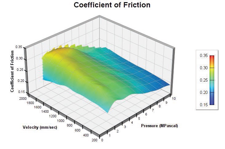 Figure 1. Coefficient of friction surface chart for the Igus J plane bearing.
The second law: Friction is independent of apparent area of contact. When two surfaces touch each other, they aren’t perfectly conformal and don’t touch each other everywhere. The area where they do contact is where friction occurs, but it can’t easily be measured. Instead, an apparent contact area is used, and the frictional force is independent of this apparent area.
The third law: The coefficient of sliding friction (also known as the kinetic friction) is independent of the sliding velocity.
The fourth law is that kinetic friction is always less than static friction. When two surfaces aren’t moving, static friction is large. Asperities micro-weld to each other and bond. When motion starts and surfaces slide relative to each other, the bonds break and don’t have time to fully form again, the friction force is kinetic. If the kinetic friction were higher, it would stop the motion.
The coefficient of friction is not a material property but, rather, a complex system response. It is related to surface roughness; environment such as temperature, vacuum or atmosphere; working conditions such as lubricant, load and speed; and bulk properties. Plane bearings are part of systems with complex relationships, and sometimes surprising behaviors can be seen in friction tests. Friction maps showing the relationships between coefficient of friction, contact pressure and velocity of various plane bearings show widely differently behaviors.
SLIDING FRICTION MECHANISMS
The first basic mechanism of friction in plane bearings is asperity interlocking. As two surfaces slide, asperities may interlock and shear or tear each other loose, creating wear debris. In general, reducing the surface roughness reduces friction.
Adhesion is the next mechanism. The Bowden and Tabor adhesive friction theory says when surfaces contact each other, they bond. On a micro scale, asperities contact each other and cause deformation and adhesive bonds. During sliding, when relative motion occurs, the bonds rupture at the interface or in the mating bodies. The shearing and breaking of these bonds result in adhesive friction.
Frictional force caused by adhesion is proportional to the real area of contact and the shear strength of those adhesive bonds. There is no way to know the real area where micro-welding occurs, only the apparent area. Robert Adams, U.S. director of engineering at Serapid, says, “The force due to friction can’t simply be calculated by looking up values in a table. But formulas can help understand the concept of what is happening in plane bearings.”
Bowden and Tabor theorized that friction was proportional to shear strength of the material and inversely proportional to surface hardness: μ ∝ τ
a/H. Maintaining low shear strength at the points of contact can keep friction down. Increasing surface hardness also decreases friction. High degrees of smoothness decrease asperity interlocking, but there might be more asperities in contact. Depending on the material, having a surface that is too smooth could increase its friction. Polyamides exhibit this behavior and will have high friction if the surface is too smooth. The rough surfaces in composite materials can shear and fill in low spots, and soon create a smooth sliding surface.
LIFE AND FAILURE
To understand how long a bearing will last, it’s important to look at wear. There are three wear models, each accepted and used by different people.
The volumetric wear rate, also known as the Archard wear rate, is used mainly in academia. It is the volume of material that is removed per unit of time, typically per hour since wear rates are low.
The specific wear rate is unitless and specifies how much material is worn in nanometers per meter of sliding distance, in nm/m (
see Figure 2). It is related to the volumetric wear rate by the contact pressure. Divide volumetric wear rate by contact pressure to get the specific wear rate.
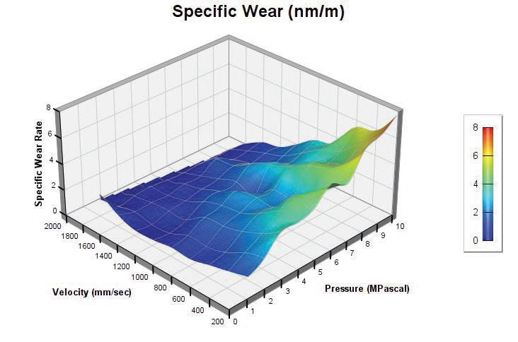 Figure 2. Wear rate surface chart for the Igus J plane bearing.
The traditional wear model is the PV model, or wear velocity. “It’s commonly seen in commercial catalogs and literature, but its units are complex, and I don’t advise using it,” Adams says. Wear rates are typically in terms of 10E-9 inches of wear per hour. It is calculated from contact sliding pressure, velocity and a material constant according to:
w = P ∙ V ∙ k
w = Wear velocity
P = Contact pressure
V = Sliding velocity
k = Material constant
“The PV power model is used in industry and has made its way into standards, specs and requirements. But for plane bearings, bearing life is really defined by the amount of allowable wear—how much material can be lost,” Adams says. Depending on the application, allowable wear may be anywhere from a few hundred microns to a few millimeters. In rolling element bearings, bearing life is generally based on fatigue. There is no fatigue in plane bearings.”
The units of PV can be written as Watts/mm
2. This implies that PV is a power model and is interpreted as the amount of energy that can go into the bearing at its surface before it fails. Graphs in bearing material catalogs show wear tests with time at various PV values. At higher PV, the wear rate is higher.
PV graphs start with design criteria and designate “safe” areas that take into account max pressure, max sliding velocity and a safe PV value (often below 10,000 psi ft/min). “But following these rules you will still fail,” Adams says. “Using the PV factor assumes it is proportional to wear. In reality, the thermal limit is what causes bearing failure (
see Figure 3). Always take PV limits on plane bearings with a grain of salt. People demand them and manufacturers provide them because they’re requested in specifications, but manufacturers won’t stand by them.”
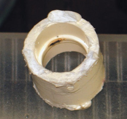 Figure 3. Plane bearing thermal failure.
Plane bearings generate heat at their surfaces. If it can’t be dissipated it overheats, causing bearing failure (
see Figure 4). A more useful tool is to look at the amount of heat generated at the surface of a plane bearing given by:
H = P ∙ V ∙ μ
where 𝜇 is the coefficient of friction. Finite element analysis (FEA) software is helpful to calculate heat flows in complex parts. As quick a rule of thumb, a conservative estimate of heat generation may be made by assuming the coefficient of friction to be 0.25. Performing a thermal analysis of the heat at the wear surface will indicate if the temperature will catastrophically climb and melt the bearing or if it will dissipate and the bearing can continue to run.
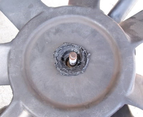 Figure 4. Fan bushing thermal failure.
PV limit testing is not a good indicator of material capability. The PV limit found is highly dependent on the heat dissipation capability of the test system. Depending on the test system, PV limits may vary by two orders of magnitude. “For published catalog, PV limit values are not a property of the material but a listing of material behavior on that particular test system,” Adams says.
PLANE BEARING MATERIALS
Many materials are used for plane bearings. Figure 5 shows a sample of the types of polymer materials used. Often manufacturers start with an inexpensive material and create good inexpensive bearings by adding friction modifiers such as Teflon or graphite to reduce friction and glass to increase stiffness. The same method can be used with expensive materials to make phenomenal bearings. “Secret sauces” are blends of the additives. When they’re added to simple polymer materials, they can create something that is very slippery.
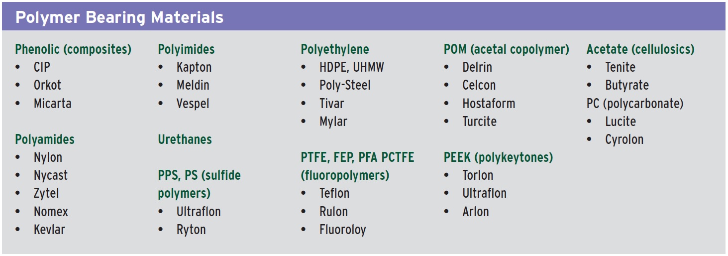 Figure 5. Polymer materials used.
The magic lubricant PTFE, commonly known under the trade name Teflon, is popular for use in bearing materials as well as hoses, fuel lines and anything else that has to last a long time and not degrade (
see Figure 6). It is chemically inert, doesn’t bond or stick to other materials well and maintains low levels of friction. It is a very smooth, long molecule that looks and behaves like oiled spaghetti, meaning that it’s slippery and hydrophobic. Water, alcohols and other highly polar oxygen and hydroxyl containing compounds won’t adhere to it, adsorb on it or wet it. This is because of the high electronegativity of the fluorine; the molecules outer electron orbitals are completely filled, making the molecule highly stable.
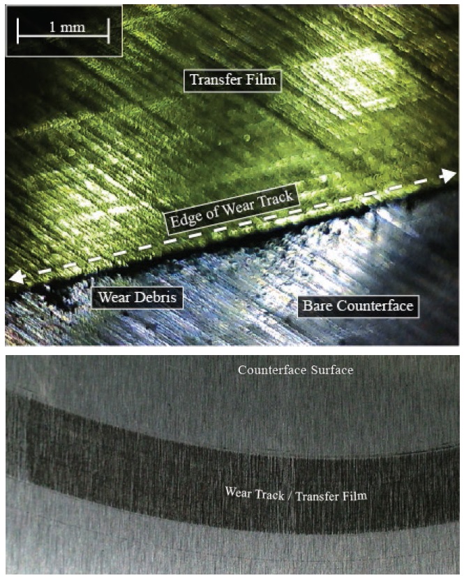 Figure 6. Teflon materials built up on the surface of a steel test disk and torn from the bearing make micro-thin coatings of the bearing material on the mating surface that can’t always be seen. They fill in the valleys in the surface. In this region there is low shear strength and high hardness, giving low friction. (Figure courtesy of Tribis Engineering.)
Graphite and other materials with similar hexagonal structures, such as molybdenum sulfide MoS
2 and tungsten sulfide WS
2, are often added to bulk materials to reach a desired lubricity. Graphite has strong in-plane bonds within its layers of hexagonal benzene rings and weak ones between layers, allowing planes to shear easily and create low friction (
see Figure 7). Metals such as nickel and silver are popular additives that strain graphite’s bonds and lower its shear strength (
see Figure 8).
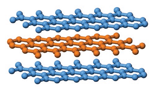 Figure 7. Singular molecular layer of graphite. (Figure courtesy of Tribis Engineering.)
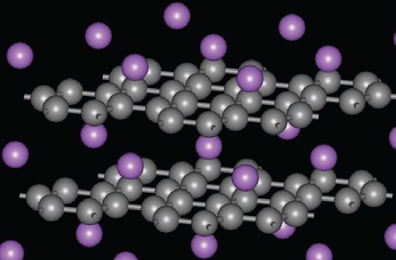 Figure 8. Intercalated graphite has metal atoms between its graphite planes that stress bonds and reduce shear strength. (Figure courtesy of Materialscientist at English Wikipedia [CC BY-SA 3.0] (click here) or GFDL (click here)], via Wikimedia Commons.)
PLANE BEARING PERFORMANCE
Figure 8. Intercalated graphite has metal atoms between its graphite planes that stress bonds and reduce shear strength. (Figure courtesy of Materialscientist at English Wikipedia [CC BY-SA 3.0] (click here) or GFDL (click here)], via Wikimedia Commons.)
PLANE BEARING PERFORMANCE
One way to measure bearing performance is to look at its wear. The dimensionless specific wear rate indicates the amount of material removed in nm, per meter of sliding distance. High quality bearing materials on planar surfaces typically exhibit excellent wear of <2 nm/m. Wear in lower cost plane bearings is typically 2-20 nm/m. When wear amounts are 20-100 nm/m, the material is considered to be moderate and not really made for plane bearings, such as unmodified low-cost ultra-high molecular weight (UHMW) polyethylene. Materials that wear more than 100 nm/m exhibit catastrophic wear and may begin to roll and look like fluff spitting out from behind a wear surface.
Lubrication is frequently used on plane bearings. It lowers its friction and adds an additional layer of protection but slows down the formation of a beneficial transfer film at the surface. The coefficient of friction in plane bearings is estimated to range from 0.05 ≤ μ ≤ 0.10 when lubricated and slightly higher at 0.10 ≤ μ ≤ 0.30 when dry. By rule of thumb, coefficient of friction is conservatively estimated to be 0.25 for most plane bearings. If an actual value is needed, test the specific material and surface condition to get a better estimate for specific operating conditions.
PLANE BEARING APPLICATIONS
Plane bearings are used in applications that cause rolling bearings to fail. They’re used anywhere with extreme loads, like in the giant Hale telescope. They tolerate far higher loads than ball bearings of comparable size.
Applications with oscillating loads cry out for plane bearings; if a ball bearing can’t roll over several times, it will fail. Oscillating back and forth, a ball bearing can’t distribute its lubrication and will fatigue quickly.
Applications with large static loads or impact loads would fracture a ball bearing, so plane bearings are used. Any applications involving low speeds, intermittent motion or vibration are good for plane bearings. Anything involving electrical potential needs plane bearings because electricity passing through a ball erodes its surface. In this case, use plane bearings without metallic fillers such as bronze or other electrically conductive materials.
They are simple bearings that can tolerate contamination and are good at wiping it out of the way. Small contaminant particles embed in the bearing material and are being removed from the wear surface. When contaminants are harder and attached to the wear surface, like the little pieces of weld spatter, they cause grooves in the bearing but not cause failure.
Plane bearings can be used in applications that work at very high speeds. “I’ve never seen a real velocity limit on plane bearings. As long as the heat can be dissipated, they can be used,” Adams says. They also offer many other advantages, are available in small sizes and a variety of materials, provide excellent vibration dampening and are impact resistant. They can run with soft metal surfaces, in vacuums, corrosive or high-temperature environments and can be tailored for their operating environment. They also can be used in environmentally sensitive applications, on soft metal surfaces and in food handling.
There are disadvantages to using plane bearings, and the majority of them involve heat. They generate heat and have poor heat dissipation. They experience higher friction than ball bearings. And a plane bearing can be thermally and electrically insulating, which could be an advantage or disadvantage, depending on its use.
Heat management is key to using plane bearings, and it’s typically overlooked. The goal is to dissipate as much heat as possible. Heat dissipation is most commonly addressed in applications with intermittent use that provide rest time to equalize temperatures. If duty cycles are kept low and there are only a few, heat management can be ignored because every time it operates it cools off before the next cycle.
FOR MORE INFORMATION
Serapid:
www.serapid.com
Tribis Engineering:
www.tribis.net/
Debbie Sniderman is an engineer and CEO of VI Ventures, LLC, an engineering consulting company. You can reach her at info@vivllc.com.