Introduction to dynamic seals
Dr. Nancy McGuire, Contributing Editor | TLT Webinars July 2017
For optimal results, you need the right combination of component, design and material.
© Can Stock Photo / sframe
KEY CONCEPTS
•
Operating conditions and fluids determine the best design and materials for a dynamic seal.
•
Multiple seal components balance the forces on the seal face and compensate for wear.
•
Equipment manufacturers can provide guidance on the best setup for a particular operation.
MEET THE PRESENTER
This article is based on a Webinar originally presented by STLE Education on May 11, 2016. “Introduction to Dynamic Seals” is available at
www.stle.org: $39 to STLE members, $59 for all others.
Steven Lemberger, CLS, graduated with a bachelor’s of science degree in mechanical engineering from the Illinois Institute of Technology in Chicago. He then joined Continental Can Co. as a research engineer. From 1979-1999 he worked at John Crane Inc. (formerly known as Crane Packing Co.) in different engineering capacities including senior design engineer. From 1999-2010 he was employed by American Electric Power D.C. Cook Nuclear Plant as a component and lubrication engineer. In 2010 he formed his consulting firm Lemberger Consulting Services, LLC, where he is the technical director.
Lemberger has served as a chairman of the STLE National Education Committee and was on the board of directors from 1999-2004. He was the chairman of the Seals Education Course and the Hydraulic Fluid Education Course. He is the founding member of the Certified Lubrication Specialist™ (CLS) Committee and holds the CLS certification. In 2009 he received STLE’s P.M. Ku Award. For more detailed information on dynamic seals, you can reach Lemberger at
mac63cd@aol.com.
 Steven Lemberger
SEALING DEVICES CAN BE STATIC OR DYNAMIC. Static seals are used to prevent fluid leakage between mating surfaces that do not move relative to each other, while dynamic seals are used when there is relative motion between the mating surfaces.
A Webinar article in the February TLT introduced the concepts behind static seals. In this article we discuss the types and components of dynamic seals. Various types of dynamic seals are designed for different applications: mechanical face seals, dynamic O-rings and labyrinth seals.
MECHANICAL FACE SEALS
Mechanical face seals are used in pumps, compressors, mixers and agitators to prevent leakage of water or lubricants. Washing machines, dishwashers and automobile water pumps, for example, all have rotating shafts, and they use mechanical face seals.
This type of seal has one rotary seal face (the primary ring) installed on the rotating shaft and a stationary face (the mating ring) installed on attached to the housing. These two rings are mounted perpendicular to the shaft axis and are in continuous contact. The seal faces are typically made from dissimilar materials to compensate for wear under the pressures and relative velocities associated with typical operating conditions.
The basic design of a mechanical face seal consists of a primary ring, a mating ring, O-rings, a retainer, disc, springs, set screw, snap ring and an anti-extrusion (anti-X) ring (
see Figure 1). Various manufacturers may use different terminology, but the components serve the same function.
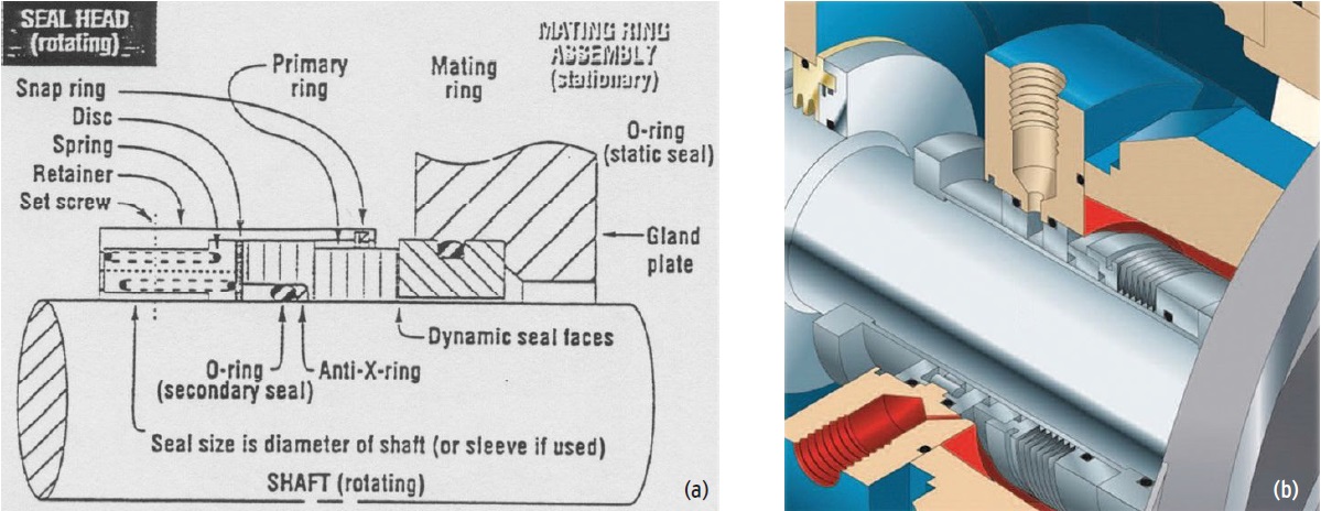 Figure 1. (a) Components of a dynamic mechanical face seal. (b) Cutaway view of a stuffing box with static O-rings. (Figure 1b courtesy of ITT Goulds Pumps.)
A retainer holds the springs that provide positive drive between the retainer and the primary ring. This spring action assures contact between the mating ring and primary ring during startup and shutdown when end-play is minimal and fluid pressure is low. A set screw in the retainer assures positive drive between the retainer and the shaft or sleeve, as well as assuring proper positioning of the seal head.
The snap ring keeps the primary ring from flying out of the retainer under pressure from the spring, and the disc ensures that the spring force is distributed evenly around the primary ring.
The metal parts are selected based on the fluid that is the seal seals. By selecting the wrong metal, the fluid can cause a chemical attack or corrosion.
Basic mechanical face seal designs include three leak points that must be sealed: (1.) between the primary and mating rings, (2.) between the stationary component and the gland plate and (3.) between the rotating component and the shaft sleeve. (The gland plate is the bulkhead between the seal enclosure and the outside, through which the rotating part passes.)
A liquid-filled stuffing box surrounds the seal faces and exerts pressure on the seal assembly. This pressure helps to maintain the contact between the two seal faces. Other elements also contribute to maintaining this mating: a tension assembly, an O-ring in the seal head containing the mating ring and an O-ring and a gland plate in the stationary assembly. The tension assembly can have springs or bellows, and it keeps the two faces firmly in contact to avoid leakage when the pump is not in operation. The O-rings provide a leak-proof contact surface between seal faces.
Dynamic face seals are designed to allow a thin lubricant film to develop between the seal faces, which lubricates and cools them. The seal faces are lapped flat to eliminate all but this minimal amount of leakage, and the degree of flatness depends on the size of the contact surfaces. The amount of leakage that forms the lubricant film depends on the size and design of the seal, the operating pressure, the temperature and the sealant liquid being used.
Regulatory requirements set constraints on the allowable amount of leakage from mechanical seals, and these vary by state (California, for example, has very strict requirements). Secondary seals, which can be stationary or dynamic gaskets, prevent fluid from escaping between the major components that contain the seal faces and the machined members.
CARTRIDGE MECHANICAL FACE SEALS
Cartridge assemblies are designed with additional parts: a sleeve, an O-ring, a gland plate and a collar with set screws (
see Figure 2). This introduces two additional sealing points: between the face of the stuffing box and the gland plate and between the shaft and the sleeve.
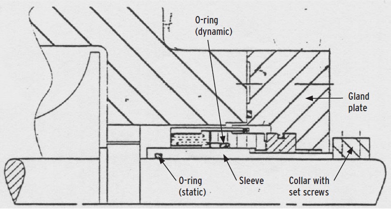 Figure 2. A cartridge mechanical seal.
The cartridge assembly has both static and dynamic O-rings. It is important that the O-rings be made from the same material to prevent mix-ups during installation. An O-ring provides a seal between the primary ring and the sleeve or shaft, and an anti-X ring prevents the O-ring from extruding between the shaft or sleeve and the primary ring.
SEAL BALANCE
Seals can be either balanced or unbalanced in a hydraulic sense (
see Figure 3). Seal balance refers to the ratio of the area exposed to fluid (hydraulic closing area) to the seal face area (opening area).
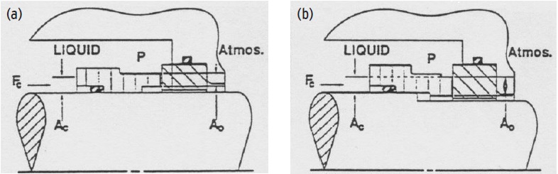 Figure 3. In an unbalanced seal (a), the hydraulic closing area is the same size as or larger than the opening area. In a balanced seal (b), the closing area is smaller than the opening area.
b = a
c/a
o
where
b = balance
ac = hydraulic closing area
ao = opening area.
Hydraulic pressure acts differently on balanced and unbalanced primary rings. In an unbalanced seal, the area exposed to the fluid being pumped (the hydraulic closing area) is the same as or larger than the seal face area (opening area), and in a balanced seal the hydraulic closing area is smaller than the opening area.
Balancing the seal reduces sliding contact, reducing power loss at the seal face. However, unbalanced seals are better at preventing leakage, so for less-volatile liquids and lower-pressure applications, an unbalanced seal might be the best choice.
If the load between the seal faces is too high, the lubricating liquid film will be squeezed out. This increases wear and damages the seal faces. Since force is pressure multiplied by area, reducing the closing area (balancing the seal) also reduces the closing force; that is, the hydraulic forces that act to close the seal faces.
The pressure in the stuffing box acts in all directions and forces the primary ring against the mating ring. The pressure acts on the closing area, so the closing force on the seal face is equal to
F
c = p a
c, where
F
c = hydraulic closing force
p = stuffing box pressure.
To control the pressure between the seal faces, the ratio between the opening and closing forces can be adjusted. One way to do this is to hold the opening area constant and reduce the closing area by adding a step to the shaft or installing a sleeve onto the shaft. Thus, all balanced seals (except the metal bellows seal) are designed with a shoulder.
O-RINGS
A 20-cent mistake in your O-rings can make you shut down your equipment, disassemble the pump and lose valuable production time, so choosing the right material and installing it correctly makes a big difference. O-rings prevent leakage by closing the passage between two parts, and they can be used with gases or liquids. The O-ring fits into a groove or channel in one seal face, and it is compressed into an elliptical shape by the flat seal face (
see Figure 4).
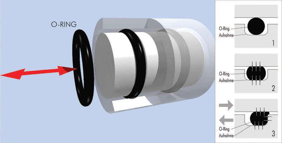 Figure 4. An improperly installed O-ring will extrude into the space between the seal faces (panel 3). An anti-X ring helps to keep the O-ring within the groove. (Figure courtesy of Wikimedia Commons, btr. Available here.)
An incorrectly installed O-ring will extrude into the gap between seal faces outside of the groove when pressure is applied. This not only causes leaks; it destroys the O-ring. Installing an anti-X ring can keep the O-ring contained in the groove.
O-rings can degrade from chemical attack, overheating or deformation. This can cause leakage, so it is important to choose an O-ring material that fits the operating conditions and the type of fluid used. O-rings are generally made from elastomeric materials, including Buna-N (nitrile), Viton (fluorocarbon), ethylene-propylene, neoprene or silicone.
Cost figures heavily into a manufacturer’s selection of materials. Thus, it’s important for the purchaser of a piece of equipment to know what the O-rings are made of and determine whether this material is appropriate to the operating conditions where the equipment will be used (
see Table 1).
Table 1. O-Ring Materials
 A comprehensive guide to fluid compatibilities with various O-ring materials is available here.
PUSHER AND NON-PUSHER SEALS
A comprehensive guide to fluid compatibilities with various O-ring materials is available here.
PUSHER AND NON-PUSHER SEALS
As the stuffing box pressure and the spring tension press the primary ring against the mating ring, the primary seal face begins to wear down. Maintaining good contact between seal faces requires a mechanism to compensate for this wear. Each type of mechanical seal has a characteristic speed limit, which determines which seal configuration can best maintain the integrity of the seal.
Pusher seals have a dynamic secondary seal that moves axially with the primary (moving) seal face (
see Figure 5). Springs maintain pressure on the seal to prevent leakage. This type of seal requires a smooth surface underneath the dynamic O-ring, and particle buildup can interfere with the smooth axial motion of this type of seal.
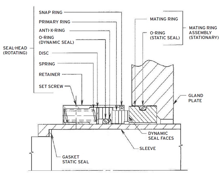 Figure 5. Single mechanical seal arrangement, pusher type.
Non-pusher seals use a secondary seal that remains stationary against the shaft or sleeve (
see Figure 6). This type of seal maintains seal pressure and shaft alignment using metal or elastomeric bellows, which expand as the primary face wears, providing the axial force needed to keep the seal faces closed. The tail section of the bellows is fixed on the sleeve, and the front convolution of the bellows moves along the shaft. The collar is fixed to the shaft by set screws. The mating ring O-ring is stationary rather than sliding down the shaft. This arrangement works best in situations where deposit buildups could interfere with the functioning of the secondary seal.
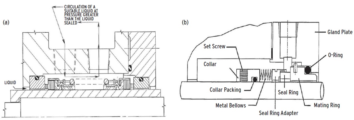 Figure 6. (a) Pressurized double mechanical seal arrangement, non-pusher type. (b) Close-up of the metal bellows arrangement for a non-pusher type seal.
LABYRINTH SEALS
Figure 6. (a) Pressurized double mechanical seal arrangement, non-pusher type. (b) Close-up of the metal bellows arrangement for a non-pusher type seal.
LABYRINTH SEALS
Labyrinth seals are dynamic seals that reduce leakage by forcing liquid to travel a tortuous path in order to reach the other side of the seal. These seals are used in bearing assemblies that are lubricated using grease or oil, and they keep the lubricant in the bearing area. Labyrinth seals provide better leakage control than do lip seals and, unlike lip seals, they do not wear or become brittle from overheating. This prevents the problem that sometimes occurs with lip seals where a worn, hardened seal wears a groove in the shaft, making the shaft unusable.
In a labyrinth seal, a stationary part called a stator wraps around a rotor with an O-ring between them. One type of labyrinth seal uses a ring with a series of knife edges attached to the rotor shaft (
see Figure 7). There is a small gap (radial clearance) between the knife edges and an abradable ring, called a land, attached to the stator. The gap allows a small amount of fluid to seep out, and the size of the gap is adjusted based on the speed of the shaft. The operating conditions also determine the pitch (spacing) of the knife blades.
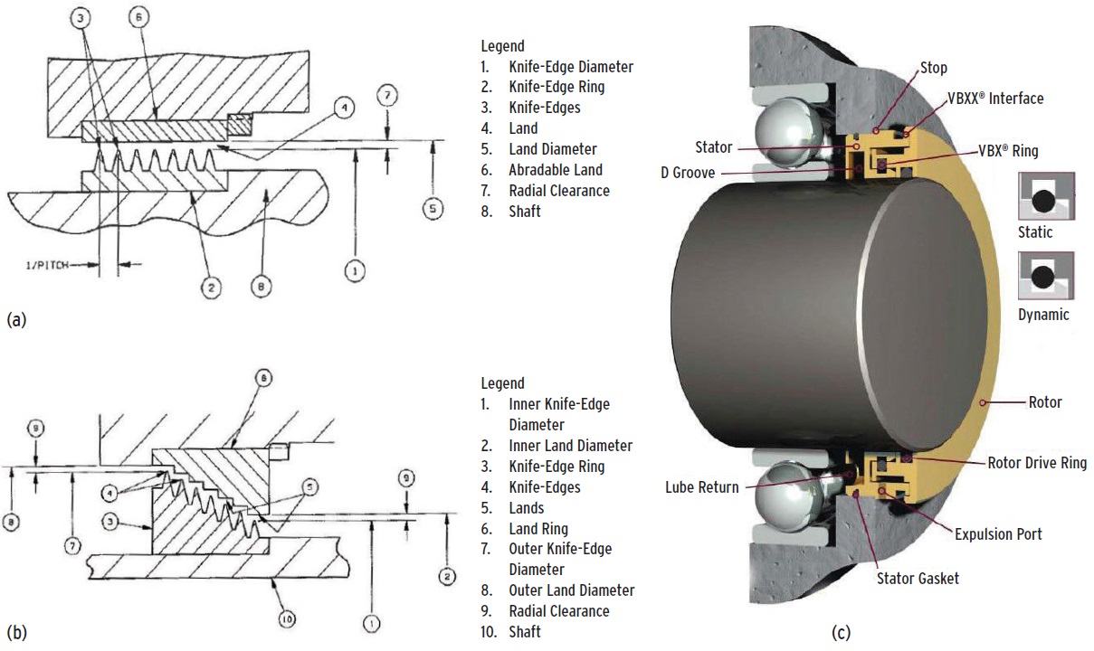 Figure 7. Types of labyrinth seal. (a) This older design has a series of knife edges on the shaft that form a small clearance with the abradable landing on the stator. (b) A stepped labyrinth seal. (c) This design has no wearing parts; the lubricant is captured in the inner portion of the labyrinth and flows back into the bearing housing. (Figure 7c courtesy of Inpro.)
In a stepped labyrinth seal, the knife edges and landing area are both at an angle to the shaft. The landing area forms series of stair steps with each knife edge pointing at the center of each landing step. This provides a longer fluid path since the clearance is on a diagonal with respect to the cross-section of the seal. Here again, the size of the gap depends on the shaft rotation speed.
THE RIGHT SETUP
Several factors go into selecting the right seal configurations and materials for a given application and operating conditions. Equipment manufacturers are a good source of help in designing the proper seals and recommending materials for O-rings and other components to ensure safety and a long operating life for your equipment. Many equipment manufacturers provide charts and literature that allow users to compare various seal materials and configurations.
 Nancy McGuire is a free-lance writer based in Silver Spring, Md. You can contact her at nmcguire@wordchemist.com
.