Rolling element bearing steels
Jeanna Van Rensselar, Senior Feature Writer | TLT Feature Article July 2017
While excellent bearing steels exist for nearly every application, there is still room for improvement.
KEY CONCEPTS
•
There have been surprisingly few applied advances in bearing steels since the 1950s.
•
The bearing industry still refers to empirical models of rolling contact fatigue (RCF) data from the 1940s that may not accurately predict bearing life.
•
With today’s computational models, a bearing can be decomposed into basic material building blocks that can be virtually tested under a range of loading conditions.
ROLLING ELEMENT BEARINGS OCCUPY THE SWEET SPOT between cost, size, weight, accuracy, load capacity, friction, durability and accuracy. Modern bearing steels are critically important ultra-high strength structural materials used in a multitude of industrial systems and subject to the highest loading conditions for, in some cases, billions of cycles. They are unique among structural materials because of the localized nature of rolling contact fatigue (RCF) loading, leading to extreme sensitivity of fatigue life to microstructural attributes.
Steel represents the material of choice in the manufacture of bearings because of its ability to sustain severe static as well as cyclic loads. Rolling element bearing steels are always selected on the basis of hardenability, fatigue strength, wear resistance, toughness and cost effectiveness.
Bearing steels, when fatigue tested in rolling contact, can typically withstand billions of stress cycles. During operation/testing, bearing steel is subjected to a complex, multi-axial stress between the rolling element and bearing raceway.
The bearing industry still refers to empirical models of RCF (
see What is Rolling Contact Fatigue?) data from the 1940s that are a very conservative estimate of roller bearing life (
1, 2). Since then, there have been several advancements in the steel itself and new insights from experimental and computational techniques (
see A History of Bearing Steels).
WHAT IS ROLLING CONTACT FATIGUE?
Rolling contact fatigue (RCF) is fatigue spall of material originating from the bearing’s subsurface. It is caused by rolling contact and is the main failure mode of rolling bearings. RCF results in metallic particles flaking from the surface of the ball and rolling elements or raceways. RCF starts as a crack below the surface and propagates to the surface causing a pit or a spall in the bearing raceway. While RCF is extremely variable, it is statistically predictable depending on the steel type, processing, manufacturing and operating conditions. Failures other than those caused by RCF are avoidable if the component is designed, handled and installed properly and not overloaded.
A HISTORY OF BEARING STEELS (3)
•
1734: Jacob Rowe applies for a British patent for a rolling element bearing. The rolling bearing materials used in Rowe’s era would have been wood, bronze and iron.
•
1856: Modern rolling element bearing steel and metallurgy are made possible through the introduction of the Bessemer process whereby air is blown through molten pig iron to produce a relatively high grade of steel.
•
1866: Open-hearth melting is invented, which further improves quality and makes steel far more accessible to the industry. However, because heat treatment of steel was still an art known only to a few, most rolling element bearings were probably made of unhardened steel.
•
1879: A British patent is issued to J. Harrington and H. Brent for a hardened steel bushing, or inner shaft, fitted with a groove for balls. About the same time, W. Hillman of Coventry, England, constructs a machine for cutting balls from steel wire.
•
1875-1900: The use of carbon and chromium steels for bearings gradually increases since the need for bearings capable of reliably supporting heavy loads increases.
•
1900-1955: There is comparatively little progress in bearing steels.
•
1955: The catalyst for quantum advances in bearing steels was the advent of the aircraft gas turbine engine. The engine creates unprecedented needs for better materials and designs for rolling element bearings. These needs included bearings for higher temperatures, higher speeds and greater loads. The ever increasing thrust-to-weight ratio for the aircraft jet engines requires the use of smaller and lighter bearings.
•
1950-1970: Steel companies and research laboratories within the U.S. began to develop bearing steels with higher alloy content.
•
1980s: AISI M-50 steel becomes the steel of choice for most high-temperature bearing applications over 149 C (300 F).
Even with this new information, several technical issues remain.
There may be a reason why bearing steels produced post-1950s endure longer in rolling bearings, but it is difficult to pinpoint since several microstructural processes are involved. There is one view that the investigation of bearing materials under torsion fatigue, which is used to observe shear-driven phenomenon, is pertinent to RCF of bearing steels. Recent investigations have employed custom-built or commercially available test rigs to characterize torsion fatigue of bearing steel. Since bearing failures develop beyond 107 cycles, some researchers have focused on rapid evaluation of shear fatigue properties with ultrasonic torsional fatigue testers.
THE MOST COMMON BEARING STEELS (4)
Dr. Xiaolan Ai, scientist for The Timken Co. in North Canton, Ohio, says, “The endurance life of a rolling element bearing is determined to a large degree by the strength of bearing material in relation to contact stresses the bearing experiences during operation. The quality of bearing steel, often measured by cleanliness among other factors, plays a critical role in determining the strength of the steels (
see Types of Rolling Elements).”
TYPES OF ROLLING ELEMENTS
There are five basic types of rolling elements that are used in rolling element bearings: ball, cylindrical rollers, spherical rollers, tapered rollers and needle rollers.
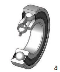 Ball bearing.
 Ball bearings have four main parts: a large outer ring, a small inner ring, steel balls between the rings and a cage to prevent the balls from contacting each other. Each race has a groove shaped so that the ball fits loosely (a). The ball deforms slightly where it contacts each race, and each race also yields slightly where each ball presses against it.
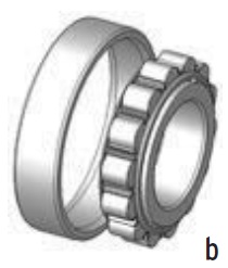 Cylindrical roller.
 Common roller bearings use cylinders that are slightly longer than the diameter. These bearings usually have higher radial load capacity than ball bearings but a lower capacity and higher friction under axial loads. If the inner and outer races are misaligned, the bearing capacity can drop quickly (b).
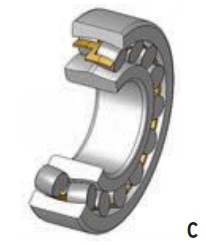 Spherical roller.
 Spherical roller bearings have an outer ring with an internal spherical shape. The rollers are wider in the middle and narrower at the ends. Because of this, spherical roller bearings can accommodate both static and dynamic misalignment. However, they are difficult to produce and, thus, expensive. They also have higher friction than an ideal cylindrical or tapered roller bearing (c).
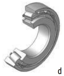 Tapered roller.
 Tapered roller bearings have conical rollers that run on conical races. Most roller bearings only accommodate radial or axial loads, but tapered roller bearings support both radial and axial loads and can carry higher loads than ball bearings. Tapered roller bearings are usually more expensive than ball bearings and produce more friction (d).
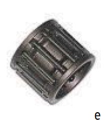 Needle roller.
 Needle roller bearings have very long, thin cylinders. Often the ends of the rollers taper to points. Since the rollers are thin, the outside diameter of the bearing is only slightly larger than the hole in the middle. Since the small-diameter rollers bend sharply where they contact the races, the bearing fatigues relatively quickly (e).
Graphics courtesy of Wikipedia.
In addition to steels, bearings also are made of ceramic, plastic and composites, depending on the performance characteristics for the application. The materials described here are the most commonly used steels.
Chrome Steel – SAE 52100. This is a good general purpose steel with excellent hardness and wear but poor corrosion resistance. It also is the most widely used material. This steel has high carbon content and about 1.5% chromium content. The finished components have a hard surface that resists subsurface RCF (
see Figure 1). The typical surface hardness for these components ranges from 60-64 on the Rockwell Hardness C Scale (Rc) (
see The Rockwell Hardness Scale).
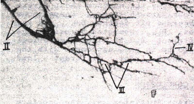 Figure 1. Subsurface cracks in rolling contact fatigue. (Figure courtesy of Sadeghi, F., et al. (2009), “A review of rolling contact fatigue,” Journal of Tribology, 131, pp. 041403-1-041403-15.)
THE ROCKWELL HARDNESS SCALE (5)
In 1914 Hugh M. Rockwell and Stanley P. Rockwell of Connecticut applied for a patent for their Rockwell Hardness Tester, with the goal of quickly determining the effects of heat treatment on steel bearing races. The Rockwell Hardness Scale is based on indentation hardness of a material. It determines hardness by measuring the depth of penetration of an indenter under a large load compared to the penetration made by a control.
There are different scales, each assigned a single letter, that use different loads or indenters. The result is a number noted as HRA, HRB, HRC, etc., where the last letter is the respective Rockwell Scale. When testing metals such as bearings, indentation hardness correlates linearly with tensile strength. This relationship permits economic nondestructive testing of bulk metal deliveries with lightweight, even portable equipment such as handheld Rockwell Hardness Testers.
Extra Clean 52100 Chrome Steel. This steel is heat treated by thru hardening it in a furnace with a controlled atmosphere. Because this steel can be highly finished, bearings made from this material tend to be very quiet. They can operate at continuous temperatures up to 120 C (248 F).
Martensitic Stainless Steels
•
AISI 440C. The high chromium content and addition of nickel makes stainless steel more resistant to surface corrosion than chrome steel. Because of reduced hardness, the load-carrying capacity is 20% lower in bearings made from this material than those made from 52100 chrome steel. Bearings made from this material are both magnetic and noisy. They can operate at temperatures up to 250 C (482 F).
•
ACD34/KS440/X65Cr13. This has a slightly lower carbon and chromium content than AISI 440C and is a popular material for rings and balls in miniature bearings. This material has the same corrosion resistance as 440C and is less noisy.
•
SV30. This steel, which is alloyed with nitrogen, has a lower carbon content than other Martensitic stainless steels. It is highly resistant to corrosion and has high strength and high hardness that can result in 100% greater fatigue life.
AISI316 Austenitic Stainless Steel. Because these bearings have a low carbon content, they are nonmagnetic and have greater corrosion resistance. The downside is that this type of stainless steel cannot be hardened—meaning bearings need to operate under low-load, low-speed conditions.
Medium Carbon Alloy Steel. Bearings made from this material, referred to as commercial grade, tend to be less expensive than other bearings. The inner and outer rings are carburized.
Low-Carbon Alloy Steel. Also referred to as commercial grade, low-carbon steel is used in bearing cages and metal washers and shields. This type of steel is protected from corrosion through either lubrication or plating.
BEARING LIFE PREDICTION
Regarding the link between structural fatigue and bearing life, Sentient Science’s (located in Buffalo, N.Y.) chief scientist, computational bearings, and STLE-member Nick Weinzapfel, says, “There is a link in a very fundamental sense if we restrict
bearing life to subsurface initiated fatigue failures. Both involve alternating or cyclic application of a load to a component, which causes the atoms composing the material to rearrange and debond to form microscopic voids or cracks that grow with successive loading until the component fails.”
Weinzapfel continues, “On the other hand, the particular stresses generated by the applied loads can have substantially different characteristics. Whereas the stresses in structural elements generally rise and fall in proportion with the applied load, stresses generated in materials subjected to rolling contact follow a complex pattern with direct and shear components that are out of phase with one another. The volume of heavily stressed material in rolling contact is highly localized and also much smaller than in structural fatigue. Still for both types of fatigue, the initial formation of damage and micro-cracks is believed to be primarily dependent on shearing stress. So despite their differences, it is likely that a correlation exists between them.”
Nagaraj Arakere, professor of mechanical and aerospace engineering at the University of Florida in Gainesville, Fla., notes that sensitivity of bearing fatigue life to microstructural attributes arises from the localized nature of triaxial fatigue loading during RCF. This leads to wide variation in subsurface initiated fatigue life of bearings tested under nominally identical conditions of geometry and loading. Because of this, probabilistic models are widely used for characterizing bearing fatigue life. The localized cyclic loading also induces plasticity at the scale of the microstructure, leading to microstructural evolution and phase transformation with cycles. The complex phenomena displayed by RCF from nanometer to millimeter length scales make reliable bearing life prediction in the gigacycle regime difficult. Current bearing life prediction models do not account for the microstructure-sensitive bearing material properties that evolve with cycles.
On the same subject, Ai says, “Qualifying the impact of the microstructure of bearing steel to bearing fatigue life would be considered as one of the most important improvements. It perhaps could be conquered in a number of steps by linking the material microstructure to its mechanical properties and then linking the relevant material property to bearing fatigue life.
“Fatigue is a very complex and challenging topic,” Ai continues. “Different industries have different practices and standards for fatigue failure prediction. The fundamental understanding on the relationship between material microstructure characteristics and fatigue performance may help to bridge the gap between various practices and standards.”
According to Weinzapfel, among the challenges in predicting the lives of bearings in real-world operating scenarios, the following three are especially significant:
1.
Operating conditions may deviate significantly from design cases due to random unpredictable environmental factors that push a bearing beyond its intended limits.
2.
Life theories are generally formulated for a particular mode of failure (i.e., material fatigue) in idealized conditions and introduce modification factors to account for other influences like contaminated lubricant or poor lubrication condition. However, they do not consider certain modes of failure that involve wear, ring fracture, etc. These unconsidered failure modes may render a bearing inoperable long before material fatigue sets in, or may act in concert with the fatigue process to accelerate the failure. Predicting the life of a bearing governed by these effects presents a significant challenge.
3.
Conventional life theories have been established on the assumption that the bearing is operating at low to moderate speeds; high-speed effects like centrifugal and gyroscopic forces are considered insignificant. In certain applications these high-speed effects can play an important role in the internal load distribution of the bearing and alter its life expectancy.
Weinzapfel explains that computational models enable investigation of bearing life in a broad spectrum of scenarios that would not be timely or cost effective through the sole use of experimental data.
“Existing life theories require parameters obtained from curve fits of bearing endurance test data that take a substantial amount of time to generate, making it practically impossible to tailor the life prediction models for every new bearing material and processing technique,” he says.
Arakere points out that calibrating empirical RCF models to material properties specific to ultra-clean bearing steels is important. “There is, as of yet, no clear link between fatigue properties (SN data using bulk specimens) of structural steels, which exhibit a fatigue limit, and RCF life of bearing steels,” he says. “RCF manifests at the microstructural scale and bulk fatigue data is perhaps not relevant. Measuring the micro-hardness evolution within the RCF-affected zone is a useful marker for microstructural evolution with cycles. Bearing life, as estimated now using virgin material properties, is not a constant value and will continuously evolve depending on loading conditions and cycles. Computational models that can characterize cyclic bearing stress fields, along with experimental approaches that can measure relevant material properties at the microstructural scale, are required for reliable prediction of bearing fatigue life.
With computational models, a bearing can be decomposed into its basic material building blocks that are virtually tested under a range of loading conditions. The relevant properties of the material building blocks and their statistical variation are determined empirically at a fraction of the time and cost of full-scale bearing test data—an advantage that scales rapidly with the size of the bearing. Once the properties are determined, a bearing’s response to actual conditions can be composed from the responses of the representative building blocks. Computational models that involve multi-body dynamics calculations enable accurate determination of the internal loading distribution at any operating speed and, thus, consider high-speed effects of centrifugal and gyroscopic forces by default.
SUMMARY
Weinzapfel concludes that advancements in simulation are needed to solve long-standing challenges, and he suggests areas to focus on. “There needs to be more ubiquitous, real-time monitoring of the actual bearing operating conditions (e.g., loads, speeds, lubrication condition, shaft-housing misalignments, temperature, etc.) in order to improve the accuracy of inputs to the models used to predict bearing life. Improvements in computational speed and multi-scale modeling techniques will be needed to more rapidly consume increasing volumes of bearing operating data and evaluate the response of virtual bearings. Additionally, these improvements would enable further consideration of microstructural details not accounted for by computational models of today.”
Arakere concludes that bridging the various length scales into a single computational framework that can be fed into finite element models to capture the 3D complexity of fatigue in bearings is a long-term goal toward designing bearings with increased life.
And where will these advancements happen? “Universities and research institutes are best aligned to conduct fundamental research work,” Ai says. “They can certainly help the bearing industry to advance our understanding on the micro-scale of the impact of material microstructure on bearing fatigue performance. This will enable bearing manufacturers and steel suppliers to explore cost-effective methods and practices to obtain desired bearing steel quality that better serves their customers.”
REFERENCES
1.
Click
here for reference.
2.
Dr. Xiaolan Ai, scientist for The Timken Co., disputes this.
3.
Rolling Bearing Steels—A Technical and Historical Perspective. Available
here.
4.
From
www.astbearings.com/bearing-materials.html.
5.
From
https://en.wikipedia.org/wiki/Rockwell_scale.
 Jeanna Van Rensselar heads her own communication/public relations firm, Smart PR Communications, in Naperville, Ill. You can reach her at jeanna@smartprcommunications.com
.