Introduction to static seals
Jeanna Van Rensselar, Senior Feature Writer | TLT Webinars February 2017
Proper design and selection contribute to longer equipment life.
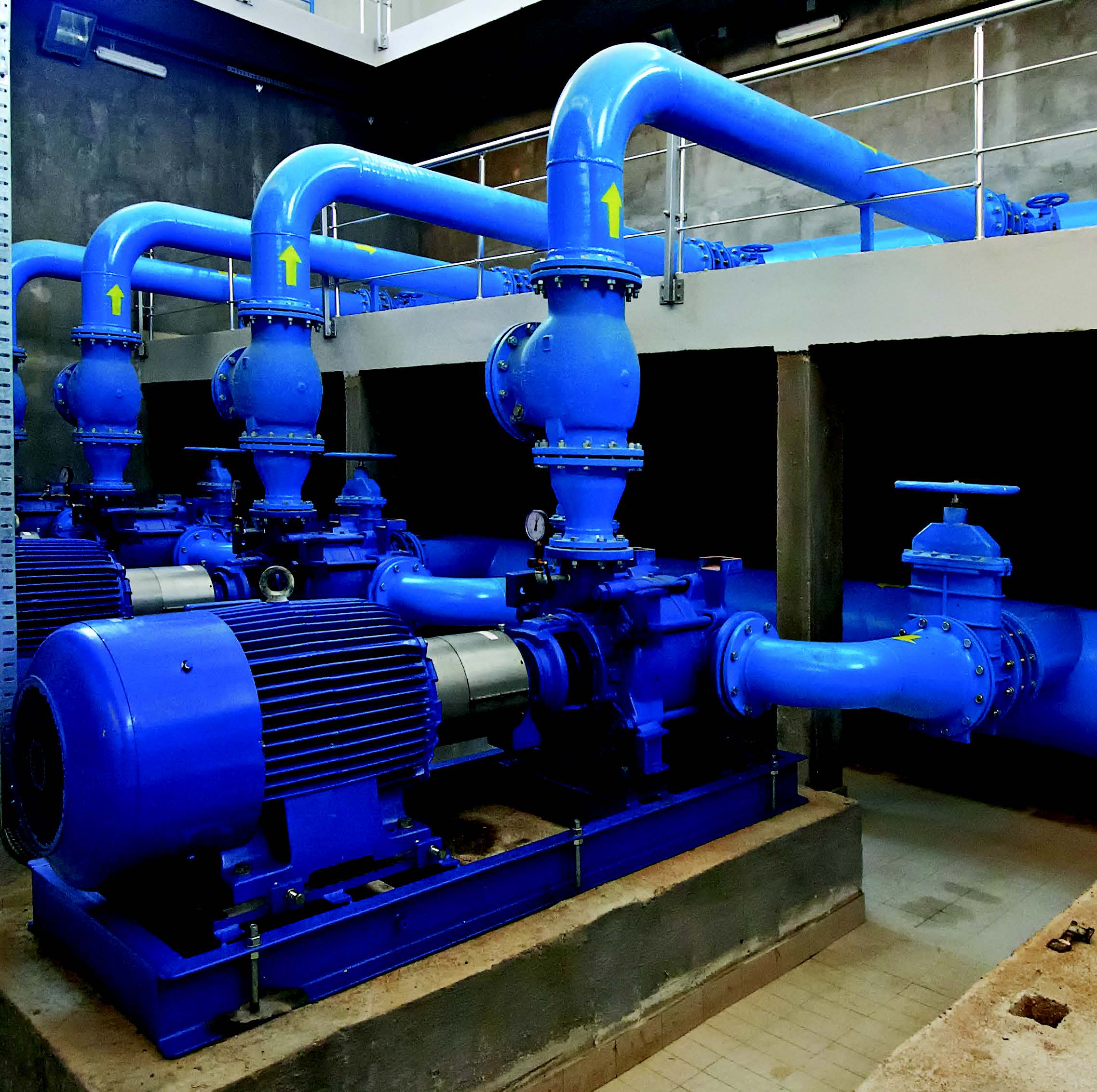
© Can Stock Photo / shime
KEY CONCEPTS
•
Static seals include packing, gaskets, O-rings and lip seals.
•
Compatibility of the fluid with seal materials is critical.
•
Important operating condition variables a seal designer must consider are pressure, temperature, speed and the viscosity of the fluid being sealed.
MEET THE PRESENTER
This article is based on a Webinar originally presented by STLE Education on April 20, 2016. “Introduction to Static Seals” is available at
www.stle.org: $39 to STLE members, $59 for all others.
Steven Lemberger, CLS, graduated with a bachelor’s of science in mechanical engineering from the Illinois Institute of Technology. He then joined Continental Can Co. as a research engineer. From 1979-1999 he worked at John Crane Inc. (formerly known as Crane Packing Co.) in different engineering capacities including senior design engineer. From 1999-2010 he was employed by American Electric Power D.C. Cook Nuclear Plant as a component and lubrication engineer. In 2010 he formed his consulting firm Lemberger Consulting Services, LLC, where he is the technical director.
Lemberger has served as a chairman of the STLE National Education Committee and was on the board of directors from 1999-2004. He was the chairman of the Seals Education Course and the Hydraulic Fluid Education Course. He is the founding member of the Certified Lubrication Specialist™ (CLS) Committee and holds the CLS certification. In 2009 he received STLE’s P.M. Ku Award. You can reach Lemberger at
mac63cd@aol.com.
 Steven Lemberger
SEALING DEVICES can be divided into two categories: static and dynamic, depending on the application. This article is confined to static seals, which include packing, gaskets, O-rings and lip seals. Static seals involve different types of packing and their uses: the function of packing, and gaskets, lip seals and O-rings—including O-ring materials and fluid compatibility.
PACKING
The packing restricts leakage between a moving and a stationary part in pumps and valves (
see Figure 1). The intent of conventional packing for pumps is to throttle or restrict—but not completely stop—the leakage between a moving and stationary part. The intent of conventional packing in valves is to stop the leakage between a moving and stationary part (
see Figure 2). This motion can be rotary, reciprocating or swinging rotary. These motions occur in pumps, valves, compressors, cylinder presses, blowers, fans, autoclaves, etc.
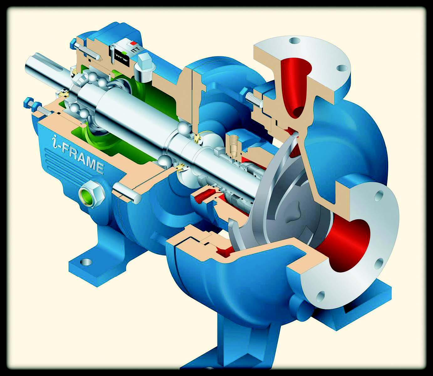 Figure 1. Section view of a centrifugal pump. (Photo courtesy of ITT Goulds Pumps.)
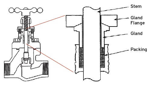 Figure 2. Valve cross section: A set of packing is installed into the stuffing box of the valve to prevent leakage. The packing in the valve contrary to the pumps must stop the leakage.
Mechanical packing can be divided into two broad classes: compression and automatic. As the name implies, compression-type packing creates a seal by being compressed between the throat of the box and the gland. Under these compressive forces the cross section of packing changes shape to expand outward to seal against the bore of the box and inward to seal against the moving shaft.
COMPRESSION PACKING MATERIALS
Compression-type packing is made from twisted, braided, woven or wrapped-type materials. There are a lot of variations in the compression packing materials including fibers, metals, lubricants and binders. The choice depends on the application.
The lubricant is added to the packing during manufacture to assure it is self-lubricated and does not burn out during the break-in period of operation.
The packing designer has to carefully consider the operating conditions such as speed, temperature, pressure, chemical reaction of liquid or gases being handled, shaft run-out, misalignment of shafts and rods coupled with the possibility of scored or grooved shafts or rods before the correct packing is recommended. Compression-type packing requires frequent adjustment to compensate for wear and loss of volume.
Automatic Packing. Automatic packing relies on operating pressure to create a seal and therefore requires little or no gland adjustment. Automatic packing is typically composed of elastomers such as:
•
Homogeneous rubber
•
Fabric reinforced rubber
•
Molded polymers
•
PTFE.
This design makes use of flexible lips to seal. In V-rings and U-cups, one lip seals against the stationary bore and the other against the moving part. Lack of lubrication causes binding and increased wear.
The Stuffing Box. The condition of the stuffing box is very important (
see Figure 3). If the inside diameter is rusty or rough, it should be reworked because it is nearly impossible to seal the outside diameter of the ring if the surface is under these conditions. When the packing is compressed, it would distort the rings unevenly and damage the shaft.
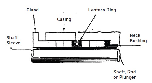 Figure 3. A stuffing box with six rings of lubricated, braided packing.
Initially the packing is snugged up with the gland. Then, as the machine goes into operation, the fluid that is being sealed will flow through the clearance between the moving parts and the packing and act as a lubricant for the packing.
The packing gland nut needs to be adjusted slightly to minimize the leakage because packing is designed to leak. If an inexperienced mechanic does not know this and tightens the nuts until the leakage is eliminated, the packing life will be substantially shortened.
If the packing runs dry, this will create frictional heat and the saturants in the packing will begin to melt and flow outward. The packing will try to adjust itself, but some of the volume in the packing is lost and leakage reoccurs. Once this vital lubricant burns out completely, the packing will dry out and will burn and score the shaft. When the packing is used at high temperatures or high pressures, frictional heat closes the gap between the packing and the moving part, and some external lubrication and cooling would then be needed.
External lubrication is used when the pumped liquid is abrasive and contains suspended solids. External lubrication also is required for those liquids or gases that are poor lubricants. This external lubrication is introduced into the stuffing box through a flush connection and a lantern ring, which is generally placed near the middle of the packing set. The external lubricant must be clean and free of abrasives. When external lubrication is introduced into the stuffing box, the pressure of the lubricant must be five to 10 psi greater than the box pressure. This will ensure the flow of lubricant in the clearance between the packing and the moving part and also will act as a fluid seal.
When the first packing is not properly seated, a gap exists between the bottom of the stuffing box and the ring, which allows distortion of the ring and causes abrasion of the shaft. This improper installation allows leakage along the outside diameter of the packing. When the lantern ring is in the incorrect position, it does not align with the inlet connection in the stuffing box and packing blocks the flush injection port.
The flush connection is blocked in the stuffing box when the packing gland cannot be further adjusted and an additional packing ring is added. The innermost ring is forced between the throat of the stuffing box, and the shaft causing damage to the shaft and the flush connection are blocked with the packing ring.
There are six steps to installing packing:
1.
Make sure all the old packing has been removed from the stuffing box.
2.
Inspect the surface finish of the stuffing box and the shaft.
3.
Select the correct packing size.
4.
Determine the required number of rings.
5.
Cut the rings or use pre-cut rings.
6.
Install the rings individually.
Packing Operation. At startup, when the gland is properly positioned (approximately 1/8 inch into the stuffing box), the leakage should be approximately 60 drops per minute. As the packing wears in, the leakage increases and the gland needs to be adjusted. The gland should be tightened gradually and evenly to reduce the leakage to an acceptable amount.
GASKETS
The function of a gasket is to create a positive seal between the relatively stationary parts and maintain the seal over a length of time (
see Figure 4). Gaskets seal by being squeezed between the faces tightly enough so that they exert more pressure against the faces than does the fluid pressure trying to leak past the faces. Gaskets would not be necessary if the surfaces were machined to mate perfectly and lapped to a good surface finish. This condition, however, would be impractical and very expensive.
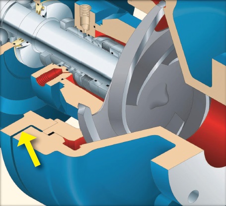 Figure 4. Location of a gasket in a centrifugal pump. (Photo courtesy of ITT Goulds Pumps.)
Chemical resistance is an important characteristic of gaskets. Use of incorrect gasket materials will function as a seal for a short time, but the gasket will rapidly fail due to chemical degradation.
Gaskets are classified based on the materials they are made from, including:
•
Metallic
•
Semi-metallic
•
Non-metallic or composite
o
Rubber (numerous types, application dependant)
o
Vegetable fiber
o
Teflon.
The most commonly used gasket materials are non-asbestos, rubber, vegetable fiber, Teflon, semi-metallic and metal. There are a lot of variables that have to be considered when selecting the proper gasket and the best practice is to follow the manufacturer’s recommendations.
Metallic gaskets are made from a single sheet of soft metal. They are used when semi-metallic or non-metallic materials are impractical. Semi-metallic gaskets are made from the composition of metal and non-metallic filler. Non-metallic gaskets are made from elastomers or a combination of elastomers and reinforced fibers. These elastomers use organic and/or non-organic polymers. Common elastomers include:
•
Neoprene
•
Nitrile
•
Ethylene propylene
•
Fluorocarbon
•
Silicone.
Gasket Replacement. Use the thinnest possible gasket and use ring gaskets when possible.
1.
Remove the old gasket.
2.
Inspect the surface finish and flatness.
3.
Center the new gasket.
4.
Tighten the bolts evenly in 1/3 increments and in a crisscross pattern.
5.
Re-torque 12-24 hours after startup.
THE O-RING
The O-ring seal is a circular ring with a circular cross section generally made from an elastomer (
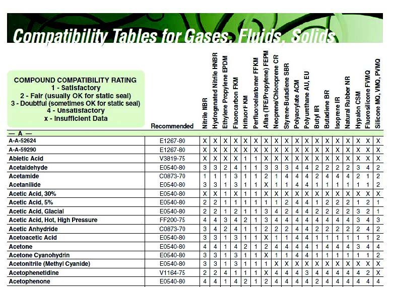
see Figure 5). They also are made from Teflon and other plastic materials and metals in the solid and hollow cross sections. The most common O-ring materials are Buna-N, Viton, ethylene propylene, neoprene and silicone. See the compatibility table (
Table 1) for the proper O-ring material as an example.
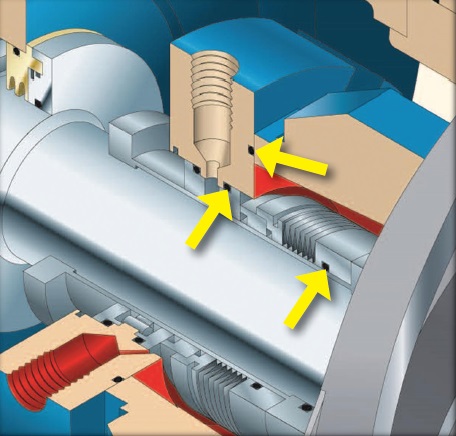 Figure 5. Locations of O-rings in a centrifugal pump. (Photo courtesy of ITT Goulds Pumps.)
Table 1. O-ring/fluid compatibility table. (Table courtesy of Parker Hannifin, O-Ring Division.)
Figure 5. Locations of O-rings in a centrifugal pump. (Photo courtesy of ITT Goulds Pumps.)
Table 1. O-ring/fluid compatibility table. (Table courtesy of Parker Hannifin, O-Ring Division.)
The function of each O-ring is to close the passage between two parts to prevent the fluid from escaping. The O-ring is always placed in a confined space and has to be squeezed mechanically to an out-of-round cross section to seal. Based on the application, the O-ring can be divided into static and dynamic categories. In the static application, the mating parts are not subject to relative movement such as a seal under a bolt, a cover plate or at piping connections.
Proper Installation of the O-Ring
1.
Lubricate the O-ring before assembly/installation.
2.
Make sure the O-ring remains in the groove during assembly/installation.
There are different ways the O-ring will fail: if the wrong O-ring material was selected or used at an incorrect temperature or the hardness of the O-ring is incorrect. It is very important to know at what temperature the O-ring is used. It also is important to ask the mechanics questions during troubleshooting and to have a seal drawing to identify the materials. In addition, it is important to know where the pump is installed.
The hardness of the O-Ring also can prevent extrusion. Low hardness rating indicates less resistance to flow. High hardness rating is more resistant to flow. The installation of an anti-X-ring would prevent the O-ring from extruding into the gap if the gap is too big. The normal durameter hardness is 65-75 for static and 75-85 for dynamic
For proper operation, O-rings are always placed in confined spaces such as a groove or channel. O-rings can function both statically (squeezed between two stationary surfaces) and dynamically (squeezed between a stationary and a moving surface) (
see Figure 5).
LIP SEALS
To be effective, the lip seal must maintain an adequate interference between the elastomeric lips (
see Figure 6). Many seal designs and lip configurations are used to meet all of the various applications. However, the basic operating principles are the same. The flexing of the elastomeric lip and the spring, as they are installed over the shaft, generates a force between the lip and the shaft that acts like a dam to keep the fluid in and the contaminants out.
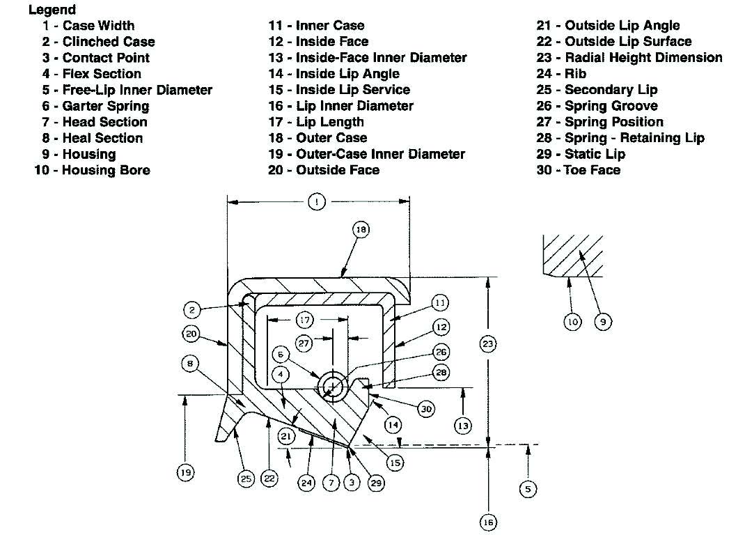 Figure 6. The elements of a radial lip seal.
Lip geometry plays an important role in obtaining the proper contact pattern and loading at the sealing interface. The oil side angle is between 40-70 degrees and is larger than the air side angle. This angle should be large enough to allow a scraping action. If this angle is too small, leakage will occur.
There are a lot of variables that a seal designer has to consider. The most important operating conditions are pressure, temperature, speed and the viscosity of the fluid being sealed. Check with the seal manufacturer for the correct seal for the application.
The lip seal only seals in one direction and must face inward to retain the lubricant. Adequate interference with the shaft needs to be maintained with a garter spring or magnetic loading. Seals are designed to mostly utilize the flexing of the elastomer and spring toward the shaft. The most common sealing materials are Viton and Teflon for petroleum products along with Buna-N for synthetics.
Because seals are an interference fit in the housing bore, they must either be pressed or driven into position. Ideally they should be press-assembled using a suitable installation tool or sleeve that has a flat face to contact the back of the seal. In the field these conditions seldom exist, and the mechanic must use alternate methods. A tube or short length of pipe, slightly smaller in outside diameter than the housing bore, may be placed squarely against the seal and tapped with a mallet. If such an article is not available, a piece of plastic or a block of hard wood may be placed squarely on the back of the seal surface and tapped lightly with a mallet as it is moved around the circumference of the seal. Never strike the seal directly with a hammer or apply force to the inner area of the seal.
A subsequent article will cover dynamic seals.
 Jeanna Van Rensselar heads her own communication/public relations firm, Smart PR Communications, in Naperville, Ill. You can reach her at jeanna@smartprcommunications.com
.