The unvarnished truth about varnish
Jeanna Van Rensselar, Senior Feature Writer | TLT Feature Article November 2016
Nothing good can come of this hard lacquer-like material once it invades lubrication systems. But there is hope for mitigation as well as prevention.
 © Can Stock Photo Inc. / annavaczi
KEY CONCEPTS
•
Surprisingly, varnish can form even when base stock and additives are relatively new, uncontaminated and thermally stable.
•
Varnish will eventually obstruct the flow of lubricant and wreak havoc with mechanics.
•
One of the primary contributing factors to varnish is electrostatic discharge.
THE VARNISH IN LUBRICATING SYSTEMS is about the same consistency as varnish used to protect wood. This varnish is a hard, lacquer-like oil-insoluble substance that is difficult to remove—great for wood, not so much for machinery. Sludge—often a varnish precursor—is a soft, pliable residue that’s less tenacious. They are both products of lubricant degradation, so the term
varnish often refers collectively to sludge and varnish and most often in the context of gas turbines.
According to an ExxonMobil Lubricants & Specialties survey of 192 U.S. power plants with a total of 626 gas turbines, approximately 40% of those generating facilities reported current or past varnish issues within six years of oil service life. Electric-power industry sources estimate today’s cost of a utility trip or no-start to be as high as $100,000 per event. In refineries, the economic impact of a turbine trip or no-start can be measured in millions of dollars per event (
1).
So why is varnish such a hot topic right now? For starters, the operating conditions for gas turbine oil are getting progressively harsher. Much of this is due to the fact that newer turbines are designed to reduce both operating and capital costs; this means tighter tolerances, 24/7 operation and—most important—the use of a common oil reservoir for the bearing and control oil. So the same turbine oil designed to service the bearings by flowing around 200 micron bearing clearances also must flow through three micron servo valves (
see Figure 1). Given this, it’s easy to see why overheating (which leads to varnish) is an issue.
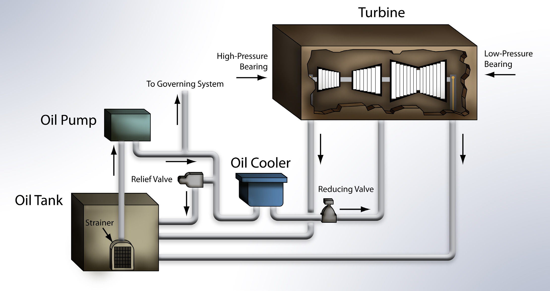 Figure 1. An illustration of the general components and travel route of turbine oil in a steam turbine lubrication system. (Figure courtesy of Lubrication Engineers, Inc.)
Potential problems caused by varnish in turbine systems include:
•
Accelerated component wear
•
Interference with mechanical part movement
•
Plugged oil inlets and strainers
•
Reduced filter efficacy and eventual plugging
•
Wholesale deterioration of the lubricant.
Varnish forms deposits and contaminates the oil stream. In some cases deposits form on equipment surfaces where the oil has degraded. In other cases the oil degrades and the insoluble decay floats through the stream—forming deposits along the way. One of the many surprising things about varnish is that it can form even when base stock and additives are relatively new, uncontaminated and thermally stable.
Whether these deposits will cure into an enamel-like coating or stay gummy and greasy depends on a number of factors including the temperature of the fluid. Either way, varnish will eventually obstruct the flow of lubricant and wreak havoc with mechanics.
Dr. John Duchowski, STLE Fellow (CLS, OMA I & II) and director of technology development, Hydac International, with U.S. headquarters in Bethlehem, Pa., and world (and R&D) headquarters in Sulzbach (Saar), Germany, says, “The exact chemical composition of varnish has not been characterized in detail. It is generally assumed that these sludgy residues consist of oil base stock and/or additive degradation products. Thus, although the term varnish itself may suggest a product of some well-defined composition or origin, in practice many different forms of varnish exist and have been observed. For example, in paper machine oils, varnish forms predominantly as a result of additive hydrolysis rather than oxidative breakdown. In contrast, in turbine lubricating systems, it is the thermal oxidative breakdown that is almost exclusively responsible for both the additive and oil breakdown that lead to varnish formation (
see Dr. Duchowski’s Advice for Avoiding Varnish).”
DR. JOHN DUCHOWSKI’S ADVICE FOR AVOIDING VARNISH
Dr. John Duchowski has the following advice for avoiding varnish in the first place.
The best way to eliminate occurrence of varnish in a new system with fresh fill is to eliminate all potential mechanisms or sources leading to its formation. This may indeed sound easier said than done, especially because not all the causes of varnish formation have been positively identified. Secondly, some weighing factors are likely to be involved as well. In terms of very simple recommendations, definitely the employment of filter elements that prevent the onset of electrostatic discharge within the system is easily and readily doable and achievable. The availability of this simple yet highly effective solution to the electrostatic discharge (ESD) issue should be of considerable appeal to both OEMs as well as the operators, as it requires little invasive intervention in order to alleviate the problem. In fact, even existing systems can be relatively easily outfitted with cartridges of suitable construction.
As the trend toward the ever-increasing market share occupied by the newly formulated Group II and III oils continues, it will become increasingly likely that even existing systems will eventually be filled with oils of this type. It should well serve as a reminder that these new oil formulations often exhibit electrical conductivities well below their Group I predecessors, this especially being true of the ashless formulations typically employed in gas turbine applications.
The ESD issue becomes all the more important because oil conductivity values have not yet made their regular appearance in any major American or European turbine lubricating oil specifications, regardless of whether intended for fresh or in-service applications. Yet, given the fact that nearly all the new oil formulations exhibit conductivities well below the critical value of 500 pS·m
–1 established on the basis of empirical observations—in fact, often well into the single digit range—conditions amenable to the occurrence of ESD at normal operating conditions already do exist in a wide variety of applications.
In view of these developments, it would be highly advisable to take the oil electrical conductivity into consideration when specifying filter elements for both hydraulic and lubricating systems where such oils are to be employed.
WHY VARNISH IS A BIGGER ISSUE NOW
Kal Farooq, principal engineer for the Pall Corp. in Port Washington, N.Y., says, “Based on field experience and talking to turbine users, two primary reasons for the widespread occurrence of varnish formation in turbine lube oil systems in recent years are (1.) more plants are operating as peakers, which means frequent start and stop of the turbines and (2.) the widespread use of highly refined Group II and III base stock oils that have lower solubility for the varnish-forming material. Peaking service puts higher stress on the oil and the resulting frequent heat/cooling accelerates the formation of deposits. This is supported by user testimonials and also by published literature on the subject.”
One of the ways to offset the stress on the lubricant caused by gas turbine design changes is to shift to a higher quality lubricant—typically a Group II or III base stock, which are more oxidatively stable. These oils can be used longer than Group I base stock, at higher temperatures, in smaller spaces and have the ability to withstand a wide range of contaminants—all reasons for the continuing shift toward Group II and III oils.
There are five American Petroleum Institute (API) base stock classifications—three for the purposes of this discussion (
2).
•
Group I solvent dewaxed base stock is the least refined—usually a mix of different hydrocarbon chains. These oils are generally used in applications without high performance demands but have significant advantages when it comes to additives, especially in terms of solubility. Because of remaining impurities, Group I oils are more polar in nature. This polarity leads to a higher solvency than other mineral oil base stocks (
see Figure 2).
•
Group II hydroprocessing and refining base stock performs acceptably in terms of volatility, oxidative stability and flash/fire points but not as well in terms of cold start viscosity, extreme pressure durability and pour point. Greater purity means that the base stock and additives in the finished product will last much longer. Fully formulated Group II lubricants have superior antioxidant properties since nearly all hydrocarbon molecules are saturated.
•
Group III hydroprocessing and refining base stock is the most refined of all mineral oil base stock. It performs well in many regards and is highly stable. Group III base stock is manufactured using the same hydroprocessing techniques as Group II base stock. The difference is the processes are more advanced in order to yield a higher VI. They also are extremely pure (hence non-polar) and may require the addition of an ester or aromatic compound to increase solvency so that they can hold additives in solution.
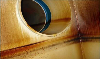 Figure 2. Since polar compounds are attracted to one another, degraded lubricants can have a greater affinity toward metal turbine parts, where they will collect as varnish. (Figure courtesy of Fluitec.)
Herein lies the problem: Lubricants with Group II and III base stocks offer much more protection for gas turbines than Group I in many important respects. But when the additives needed to increase solvency deplete, the other additives begin to separate and form varnish. This isn’t just a problem for gas turbines; it’s just
more of a problem for gas turbines.
“In particular, the greater degree of refinement typically employed for modern lubricating oils reduces the content of unsaturated hydrocarbons and sulfur-containing species,” Duchowski says. “In turn, the lower content of these polar materials significantly reduces their solvency toward the oxidative degradation products, which are often likewise polar. One consequence of these poorer solvency characteristics is the inability of the fluid to dissolve its own degradation products, which manifests itself in the appearance and accumulation of varnish in hydraulic and/or lubricating systems.”
In addition to the solvency issue with Group II and III base stocks, there also is a significant decrease in electrical conductivity—which introduces the problem of electrostatic discharge.
VARNISH FORMATION
Joe Z. Zhou, senior research chemist for Chevron Lubricants in Richmond, Calif., says, “The primary cause of varnish is degenerated lubricant oil species, which are primarily oxidized hydrocarbon molecules. These species go through surface aggregation and further surface reaction processes to form varnish.”
The typical route of varnish formation begins with thermal degradation and progresses to oxidation, which produces contaminants that result in sludge and varnish.
•
Thermal degradation. Thermal degradation happens at temperatures above 299 C (570 F) and leads to oxidation. There are four potential sources of heat:
1.
Full spark discharge. With flash, it will generate nanosecond temperatures from 10,000 C (18,032 F) to 20,000 C (36,032 F).
2.
Dark stream spark discharge. With no flash of light, temperatures between 5,000 C (9,032 F) and 10,000 C (18,032 F) can be generated.
3.
Friction. The combination of oil against the metal surfaces in the system, as well as metal parts rubbing together, can generate temperatures between 180 C (356 F) and 450 C (842 F).
4.
Adiabatic compression. This can generate temperatures between 600 C (1,112 F) and 900 C (1,652 F) (
3).
•
Oxidation. Oxidation is accelerated by exposure to temperatures of 249 C (480 F) and above. Elevated temperatures accelerate the oxidation process; for every 10 C (50 F) increase in operating temperature, the rate of oxidation doubles (
4). The presence of aeration, water and metals accelerates oxidation. Once underway, oxidation byproducts develop into insoluble contaminants.
•
Contamination. Although contaminants come from a variety of sources, internal contamination is most often submicron oxidized oil that agglomerates to leave deposits. Certain oil additives can create more varnish than others—including some rust inhibitors. These contaminants agglomerate into sludge and varnish (
see Figure 3).
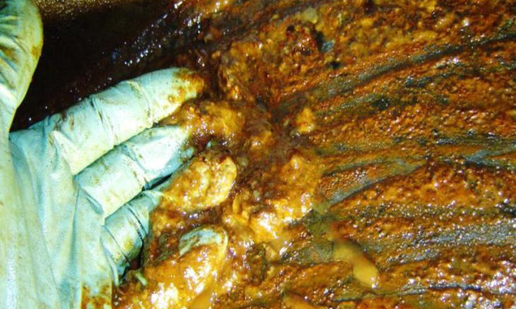 Figure 3. When large quantities of varnish accumulate in the oil, they begin to precipitate out of solution into a thick gooey layer of sludge. (Figure courtesy of Greg Livingstone and Fluitec.)
Duchowski says, “Field experience based on several years of empirical observations as well as ample experimental evidence strongly suggest that one of the primary contributing factors to accelerated oil and additive degradation is the oxidative breakdown caused by the electrostatic charging of filter elements employed in the turbine lubricating system. Awareness of the occurrence of electrostatic discharge (ESD) in hydraulic and lubricating systems has persisted now for well over a decade, yet relatively few steps have been implemented by equipment manufacturers or operators in order to avert ESD or even to minimize its impact on system performance.”
ELECTROSTATIC DISCHARGE
ESD is produced by friction that results when two surfaces move in relation to each other—this usually means they must come in contact with each other, but not always. When it comes to liquids like lubricants, the charge occurs on the molecular level at the place where the materials meet. The positive or negative charge that is generated by the moving fluid will migrate from the fluid to the surface it comes in contact with. Common causes of electrostatic charge in a system include one or more of the following:
•
Fluid flowing through narrow passages
•
Fluids passing through filters
•
Fluids that travel through systems at high speeds and/or are highly agitated
•
Fluids that are kept at lower temperatures
•
Fluids that become aerated.
Streaming current occurs when the fluid carries the charge downstream of the source. As the charged fluid flows, it deposits current along the route. If the surfaces it encounters can conduct electricity and are not grounded, then a charge (opposite the charge of the fluid) deposits on the walls. If the surfaces are either not capable of conducting electricity or grounded, the charge will build up and discharge as static. These discharges can generate sparks with temperatures greater than 10,000 C (18,032 F)—depleting antioxidants and seriously degrading the oil.
According to extensive research by Duchowski and others, ESD leads to the formation of free radicals within the oil, which leads to uncontrolled polymerization that culminates in the buildup of insolubles like varnish and sludge.
FILTRATION AND STATIC
The transition to synthetic and glass filters with tighter pores coupled with higher filter flow rates has created a perfect storm for ESD. A high flow rate creates high voltages that result in more powerful and frequent spark discharges. If the filter is made of nonconductive materials like these, the charge will not be able to dissipate into the filtration system. Then the filter will charge until the voltage reaches a certain point and discharge to conductive parts such as the metal components of the filter housing—causing significant damage. While grounding the filter system will prevent sparking, it will not prevent either the filter or fluid passing through it from charging and causing damage.
Past attempts to reduce the potential of ESD accumulation have included:
•
Adding an antistatic additive to the fluid. The additive will raise the conductivity of the fluid and accelerate the rate of charge dissipation, but it is usually added to fuels and not lubricants. Antistatic additives have not been approved for use in hydraulic and lubrication systems.
•
Reducing the charge exiting the filter. This was accomplished by using a static charge reducer (SCR)—a passive device that injects a charge of the opposite polarity into the charged fluid during flow. This was a less than ideal solution because of the lag time before the effects kicked in and the fact that the SCR became contaminated by conductive layers—making it ineffective.
•
Reducing the filter’s flow volume. This was accomplished by increasing the filter size or using parallel filters. While this is a simple and effective solution, engineering considerations make it impractical in many cases.
•
Creating more time for the charge to dissipate. This also was an effective but impractical (and costly) solution since it required re-engineering the system to increase the distance of the fluid route and/or adding a reservoir.
•
Adding a grounded conducting surface. While this creates better conditions for discharge and seems to reduce or eliminate surface damage to materials, it doesn’t solve the basic problem of fluid charging (
5).
The only practical way to keep the filter and fluid from charging is to reduce the charge generation at its source (during filtration), which would mean altering the filter components.
“Sparks generated as this charge discharges generate very high localized temperatures, which literally burn the fluid, cracking the molecules and forming free radicals that further promote fluid degradation through additive depletion and oxidation,” Farooq explains. “The end result is accelerated fluid degradation and elevated levels of oil insoluble materials. Antistatic lube oil filters are available to prevent this from happening.”
REMEDIATION
The following are four types of varnish mitigation systems currently available:
•
Liquids—electrostatic liquid cleaners (ELC)/chemical cleaning fluids. Using electrostatic forces to attract polar contaminants, ELCs work by passing the oil over a series of anodes and cathodes. Negatively charged particles are attracted to a positive collection zone and positively charged particles to a negatively charged zone. Electrostatic oil cleaners require a non-conductive environment to function and are sensitive to small amounts of water contamination. They are effective devices for removing submicron insolubles, including insoluble oil degradation products. Zhou says, “Our opinion is that the best technology for
removing existing varnish is by using chemical cleaning fluid. It would be best that this fluid is compatible with in-service fluid and can efficiently remove varnish.” Farooq suggests adding chemical cleaning as a separate category (
see Does Removing Varnish From the Fluid Also Clean the Surfaces Within the System?).
•
Charge agglomeration. The particles are charged with electrostatic forces and forced to agglomerate in size. Agglomeration occurs not in the filtration equipment but when the oil returns to the lubrication system. When the sub-micron particles agglomerate to multi-micron sized particles, they are removed through conventional mechanical filtration. Like ELCs, agglomeration units are sensitive to water.
•
Depth media filters. These units are effective at removing smaller amounts of polar submicron contaminants that are in suspension. However, if the oil is heated to above the melting point of the contaminants, all of the filtered oil degradation products will melt back into solution, re-contaminating the fluid.
•
Electrophysical separation process. This technology was designed to remove organic soft contaminants from the lubricants. The unique aspect of this technology is its ability to remove oil degradation products that are both insoluble and soluble. It does not impact other additive components in the lubricant, nor is the filter media affected by water or other contaminants (
6).
DOES REMOVING VARNISH FROM THE FLUID ALSO CLEAN THE SURFACES WITHIN THE SYSTEM?
The consensus seems to be that once varnish begins forming on surfaces, it is very difficult if not impossible to remove. Kal Farooq says, “If the deposits are already hard and lacquer-like, which is influenced by their chemistry and how long they have been in place, it will be difficult for this type of deposit to get back into solution in the oil—thus, it will not be completely removed. Relatively new, softer deposits are more prone to dissolution and removal by the oil as it is cleaned up.”
Joe Z. Zhou agrees: “To my knowledge, the technology to remove varnish precursors in fluid can’t effectively clean surfaces within the system since the deposition of varnish film is typically not reversible. Additionally, there is no guarantee that the varnish removal technology will remove all types (organic, organometallic, inorganic, etc.) of varnish.”
Dr. John Duchowski adds, “An argument that is often made in this regard is that the fluid is capable of solubilizing a certain quantity of varnish, beyond which point varnish becomes insoluble. Once the varnish content within the fluid drops below its saturation point, more varnish can be dissolved within the fluid, which suggests that this could be a mechanism by which the entire system can get cleaned up.”
He continues, “However, in practice, several other things need to be considered, one of them being the adhesion of varnish to other system components—notably large metallic surfaces presented by the piping network and/or reservoir floor and walls. In addition, varnish solubility throughout the system also will be dependent on the system temperature profile and flow turbulence. This means that in dead zones or zones with lower flow velocity and/or cooler spots, varnish will be harder to remove and possibly will not simply be re-dissolved into the fluid, even when the varnish content within the fluid has dropped below the saturation limit.”
“Opinions are widely divided on this topic (of remediation) and, somewhat unfortunately, tend to be highly dependent on product availability and the marketing approach,” says Duchowski. “They include everything from the use of highly absorbent/adsorbent cellulose-based filter media through systems employing high efficiency filter media assisted by oil cooling and, finally, to the use of ion-exchange resins, which function here also solely as adsorbent materials. The main point being that varnish precursors tend to be soluble at typical operating temperatures up to the point when enough of them accumulate within the system to agglomerate and form sludge. At that point, even relatively coarse filter elements would be subject to blockage, but that point is usually considered too late for effective varnish treatment.”
He continues, “Unfortunately, no quantitative data that could be used for an objective comparison of all these methods exist, making it very difficult to say which method provides the best results. In addition, the effectiveness of each depends on the available surface area, fluid turnover rate, the
intrinsic propensity of the employed media to absorb/adsorb varnish materials and the operating conditions—most notably temperature. In practice, therefore, the treatment methods based on lubricant cooling and subsequent filtration seem to offer the best results on the grounds of superior surface area and ease of use.”
Farooq says, “The technology that we know works very effectively is the adsorbent media technology that is engineered to have high affinity for the polar varnish precursors in the lube oil. The media has large surface area and high void volume, relatively low fluid flux and has electro-chemical affinity for the varnish precursors. Its working principle is Physisorption—a process in which the adsorbent material and the adsorbate (varnish precursors) are bonded by weak electrostatic forces arising from induced dipole moments such as van der Waals forces. Because of its chemical structure, varnish molecules are attracted to the adsorbent through electrostatic forces and hydrogen bonding.”
DEALING WITH SERIOUS VARNISH FORMATION
Duchowki says, “The treatment of a serious varnish problem depends on the remaining additive content in the lubricant (about 75%). Should that additive content be measured sufficient by the established methodologies, the treatment method I referred to earlier (lubricant cooling and subsequent filtration) can be successfully applied. Should the additive content have dropped below 75%, the chemical flush remains the most appropriate option. Probably the best method for dealing with a serious varnish problem remains a thorough system flush, perhaps even a solvent or detergent assisted flush. At the very minimum the flush should be performed with twice the velocity or volume flow of that employed at normal operating conditions, but, better yet, conditions should be set up such that at least the minimum Reynolds number (
7) of 4,000 is reached, though values higher than 10,000 have often been employed and recommended.”
For systems experiencing serious varnishing issues, Farooq advises the identification of the underlying causes of varnish formation and their elimination as the long-term remedy. For the immediate control of the problem to keep the turbine running until the next outage (
see Figure 4), as is the case in most plants, he advises the following.
•
Deploy a varnish mitigation system such as engineered adsorbent media type to start the cleanup of the oil.
•
Measure the oil condition by Membrane Patch Colorimetry (MPC) Test on a weekly basis to monitor oil cleanup until the MPC ∆E values are under 15.
•
Replace the servo valves, if needed, as a preventive measure to avoid turbine trip since that is the most costly and disruptive consequence of the varnish problem.
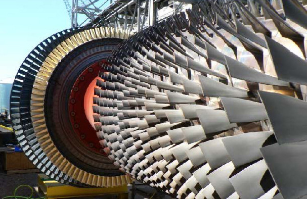 Figure 4. Steam turbine. (Figure courtesy of Greg Livingstone and Fluitec.)
Zhou says the best way to handle a serious case of varnish formation depends on a root cause analysis of the system, but generally:
1.
Identify the root cause of oil degeneration and varnish formation.
2.
Clean the system using the appropriate varnish removal technology.
3.
Put in place necessary engineering and maintenance controls for the system.
PREVENTION
Preventing varnish from developing in the first place with a well-balanced formulation of high-performance base stock and advanced additives is a sound strategy. To that end, the following should be considered.
•
Deposit control. As mentioned earlier, varnish can be generated by thermal degradation, oxidation and contamination. Some oils generate more deposits than others, but advanced turbine oils are formulated to limit the generation of sludge and varnish, while keeping deposits in suspension.
•
Air release and foam control. Entrained air in oil with inferior air release performance may be compressed in turbine bearings or high-pressure hydraulics, causing adiabatic compression (micro dieseling). Adiabatic compression can cause localized elevated oil temperatures that may promote the formation of varnish. Similarly, excessive surface-level foaming can accelerate oxidation. Oils formulated for rapid air release and minimal foam formation will provide superior protection against varnish.
•
Filterability. This refers to a fluid’s ability to pass through a filter with minimal pressure drop. Oils with poor filterability will pollute filters faster, which might require more frequent filter changes.
•
Antirust and corrosion protection. Rust and corrosion contribute to oxidation and the formation of contaminant-based varnish.
•
Wear protection. Since wear metals act as an oxidation catalyst, wear material from machinery components can lead directly to varnish formation (
9).
Farooq says, “All turbine lube oils degrade during service, which produces oil insoluble products and the resulting deposits or varnish. As a preventive measure, it is recommended to install varnish mitigation systems to prevent buildup of the varnish precursors to a point that they form damaging deposits on critical operating surfaces such as servo valves and the rest of the lube system.”
Zhou says, “Using a properly formulated premium quality lubricant with proven
low varnish potential is the most effective way to prevent varnish formation in turbine oil systems. Approaches to formulation of these types of oils include balancing the base stocks with carefully selected additives and/or having a lubricant with varnish dissolving properties. One example of a varnish prevention oil (
see The 100% Varnish Prevention Solution) would be an oil, which passes the MHPS Dry TOST Test.”
THE 100% VARNISH PREVENTION SOLUTION (8)
According to Greg Livingstone, executive vice president of business development for Fluitec International in Jersey City, N.J., it is possible to prevent all damage from gas turbine lubricant varnish. Following is his five-point varnish prevention program:
1.
Choose a good oil.
2.
Monitor oil condition.
3.
Minimize sparking.
4.
Maintain the oil.
5.
Remove contaminants.
OIL ANALYSIS
Appropriate tests for analyzing sludge and varnish depend on the failure mechanism (
see Figure 5). According to some experts, common oil analysis testing methods do not accurately predict varnish. These tests include:
•
Rotating Pressure Vessel Oxidation Test (RPVOT) ASTM D2272
•
Acid Number ASTM D664 or D974 increase
•
Particle Count with ISO 4406 Cleanliness Code.
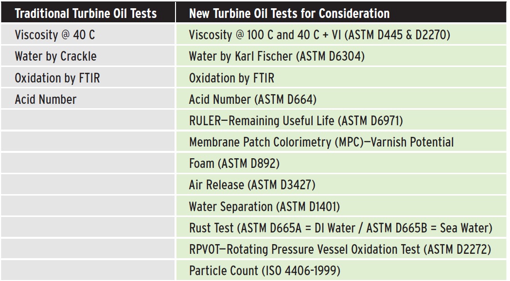 Figure 5. A list of traditional tests routinely employed for industrial oils at commercial labs versus a list of tests that should be considered with specific choices dependent upon the current operation of the turbine. (Figure courtesy of Lubrication Engineers, Inc.)
A better approach is a combination of the following three tests:
•
Ultracentrifuge, which predicts varnish.
•
MPC identifies the contamination level in used oil as it relates to oil degradation and potential varnish development.
•
Remaining useful life evaluation routine (RULER) identifies levels of antioxidants (
10).
Sampling and testing should be performed at least quarterly—more frequently as the oil condition degrades. Trending yields valuable insights into the condition and remaining service life of the oil and equipment.
Varnish is a serious problem with the potential to shut down critical equipment and cost millions of dollars in downtime and lost productivity. So:
•
Is varnish becoming an increasing problem?
Yes.
•
Do researchers know what causes varnish?
Yes.
•
Is varnish preventable?
Yes.
•
Is it entirely preventable?
Probably not.
•
Can it be removed once it starts forming?
Yes and no.
•
Is more research needed on varnish prevention?
Definitely.
REFERENCES
1.
From
Vanquish varnish to improve gas-turbine reliability, by James Hannon, ExxonMobil Lubricants & Specialties Co., and Andrea Wardlow, ExxonMobil Research & Engineering Co. Available
here.
2.
Group IV or PAO (polyalphaolefin) base stock is a chemically engineered synthetic. It has a highly stable chemical composition and is increasingly present in synthetic and synthetic-blend products for industrial and vehicle applications. Group V base stock is usually blended with other base stock. It is used in small amounts as secondary base stock to impart discrete lubricant properties. This base stock is capable of accommodating a wide variety of properties and custom formulas. Because of this it provides the base ingredient for many additives.
3.
From
Problems and sources of varnish in hydraulic fluid by Lew Lucas. Available
here.
4.
This is a generalization of the Arrhenius Equation: a formula for the temperature dependence of reaction rates. The equation was proposed by Svante Arrhenius in 1889.
5.
From Van Rensselar, J. (2012), “Static discharge in lubricants,” TLT,
68 (9), p. 50.
6.
From
The emerging problem of lubricant varnish by Greg Livingstone and David Oakton. Available
here.
7.
The Reynolds number is an experimental number used in fluid flow to predict the flow velocity at which turbulence will occur.
8.
Day, L. (2008), “Solving varnish problems in gas turbine lubricants,” TLT,
64 (1), pp. 37-38.
9.
From
How to vanquish varnish by James Hannon, product technical advisor for ExxonMobil Fuels, Lubricants & Specialties Marketing Co. Available
here.
10.
From
Vanquish varnish to improve gas-turbine reliability by James Hannon, ExxonMobil Fuels, Lubricants & Specialties Marketing Co. and Andrea Wardlow, ExxonMobil Research & Engineering Co. Available
here.
 Jeanna Van Rensselar heads her own communication/public relations firm, Smart PR Communications, in Naperville, Ill. You can reach her at jeanna@smartprcommunications.com
.