Improving equipment reliability with ultrasound
Debbie Sniderman, Contributing Editor | TLT Webinars July 2016
Reliable, versatile and low cost, the handy condition monitoring tool serves in multiple applications.

© Can Stock Photo Inc. / ekipa
KEY CONCEPTS
•
Set baseline and alarm levels and know what good and bad sounds like using history and comparisons.
•
Powerful reporting and documentation methods make it easy to use ultrasound for condition monitoring.
•
Ultrasound assists in preventing bearing over- and under-lubrication.
MEET THE PRESENTER
This article is based on a Webinar originally presented by STLE University on Oct. 28, 2015. “Improving Equipment Reliability Using Condition Monitoring with ultrasound” is available at
www.stle.org: $39 to STLE members, $59 for all others.
Adrian Messer is manager of U.S. operations for U.E. Systems Inc. For more than a decade he has helped transform companies’ reliability programs by implementing ultrasound technologies for condition monitoring and energy conservation applications. He is a subject matter expert on ultrasound technology and implementation best practices and has been a featured speaker numerous industry events.
As a Clemson University graduate, he maintains close ties with the university mentoring current students in the College of Business and Behavioral Science. Messer is a Certified Maintenance and Reliability Professional through the Society for Maintenance and Reliability Professionals (SMRP) and a charter member of the Carolina’s SMRP chapter.
Messer can be reached at
adrianm@uesystems.com.
 Adrian Messer
ULTRASOUND CAN EASILY BE IMPLEMENTED INTO ESTABLISHED MAINTENANCE AND RELIABILITY PROGRAMS that are currently using vibration, infrared or other condition monitoring analysis technologies. The best maintenance and reliability programs are those that don’t rely on one single technology but use multiple technologies to gather as much information about the health of assets as possible. It is a perfect complement to what is already being used.
Good maintenance and reliability programs include techniques that help find and prevent failures earlier such as condition monitoring. Finding failures earlier gives time for proper planning. Repairs are much less expensive when they are made earlier rather than waiting until equipment has seized.
After a new item of equipment such as motor or pump is installed and started, there are many things a facility can do to extend the window of time that it operates without failures, commonly called the I/P interval on the IPF curve, a fundamental concept of reliability. One example is performing precision alignment before starting it up. If it is started up out of alignment, the I/P window has been shortened, initiating an early potential failure.
While in the proactive domain, using ultrasound to properly lubricate bearings helps extend the I to P interval and life of the bearings by preventing over-lubrication or notifying when proper repairs could be made before a failure occurs.
Once a failure has been initiated (labeled P on the IPF curve) and equipment is operating in the predictive area, condition monitoring technologies such as ultrasound, vibration analysis, oil analysis and infrared can be used to delay and avoid entering the fault domain where there may be no recovery. In the severe fault areas, beyond infrared, there are indications of faults, such as audible noises and surfaces that are hot to the touch, where equipment can no longer operate or run the way it was designed.
Ultrasound is located very near vibration on the IPF curve, and it is very effective in finding early-stage bearing failures. For example, when a bad bearing causes a race fault condition on a 50hp motor, its sound is hidden from human ears. If the motor continues to run with the hidden noise, ultrasound can record sound files that can pick apart the inter-race harmonics with spectral analysis techniques, and then vibration analysis techniques can be used to identify the precise fault condition. Vibration as a technique is excellent at finding some failure modes that ultrasound doesn’t, such as misalignment. Using the two techniques together, any kind of mechanical failure can be found.
WHY ULTRASOUND?
A commercial technology that has been around since the 1960s, ultrasound has matured from mainly portable handheld analog instruments that looked for compressed air leaks on pressurized phone cable lines to the first pistol grip and Ultraprobe systems made by UE Systems to digital instruments which provided true dB numbers. In the early days, it was primarily a search-and-locate technology. Recently, it has trended toward being more diagnostic, meaning it can pinpoint and identify specific bearing and electrical fault frequencies making it no longer only used for leak detection.
The first ultrasound instruments with on-board sound recording became available in the early 2000s, and today’s instruments have an increased emphasis on sound recordings and data collection. Instruments of the past recorded sound, but now the focus is on what can be done with the sounds.
Listening provides dB levels, and the sound can be recorded, played back, visually displayed, and spectrally analyzed using Fast Fourier Transforms (FFTs) and time waveforms. These can be used to determine more about electrical noises from energized electrical equipment and mechanical problems in rotating equipment.
Most recent advancements in ultrasound technology have been made in the reporting and documentation areas. Multimedia reports compile multiple sound files, trend charts with alarms and waveform or FFT views and combine digital and thermal images made with IR cameras. Point-specific reports, alarm reports and lube route reports are helping ultrasound be more widely adopted for condition monitoring, predictive maintenance, energy conservation and inspections where safety is a concern.
The future of ultrasound is being able to view spectrums in real-time and analyze recorded sound spectrums on the fly to detect failures even earlier. There are also advancements in using ultrasound for remote continuous monitoring.
A VERSATILE TECHNIQUE
Leak detection is a core energy conservation application for air-borne and structure-borne ultrasound and the easiest ultrasound application a facility can perform. It is common that in only a few days, ultrasound will find and document enough leaks in compressed gases like N2, He, Ar or O2 in a facility to more than pay for the cost of the equipment. It can also find and generate similar reports for leaking steam traps, saving facilities the cost of excess steam.
Ultrasound also helps safely perform electrical inspections and gives a heads-up warning so proper precautions can be taken before opening cabinets. Scanning around seals of doors and louvers can help detect arcing, tracking, or coronas inside a cabinet without having to open its panels, reducing the risk for an arc flash.
It is also used as part of reliability and condition monitoring programs wherever there is rotating equipment, on bearings and for condition-based lubrication. The second easiest application for ultrasound is in Ultrasound Assisted Lubrication. It helps precision lubricate bearings to know when to apply grease and when too much has been applied to prevent over and under lubrication.
WHAT IS ULTRASOUND?
Ultrasound instruments are devices that listen for high-frequency sounds that are too high to be heard by human hearing. The air-borne and structure-borne devices don’t emit anything like the pulse-echo type ultrasound devices commonly used in medical applications. Rather they are tunable to listen in the 20-100 kHz range, translate sounds to be converted to the audible range and played into headsets and be recorded by the instrument.
Air-borne ultrasound systems used for mechanical inspections typically record 40 kHz sounds. 30 kHz is used for bearings or rotating equipment unless they are slow speed bearings or steam trap applications which use a 25 kHz setting. The slowest speed bearings or anything below 100 rpm use the lowest 20 kHz setting, which is still well above the maximum frequency that humans can hear, which is around 17 kHz.
By nature, high frequency sound waves are very directional. While low-frequency sounds can travel far because they have high amounts of energy, high-frequency sounds are low energy sounds and don’t travel very far. Ultrasound instruments make it easy to locate the sources of these sounds.
Because of the frequency range and its directionality, there is no concern about using ultrasound when there is background noise or other machines running. Ultrasounds can be heard above normal plant noise, and devices listen only for sounds that can’t be heard.
Ultrasound instruments report sounds using decibels (dB) as the unit of measurement. Decibels are recorded and displayed over time so trends can be viewed. Any increase in a dB level indicates a change has taken place, and alarms can be set when levels change more than the recommended dB units above a baseline.
Ultrasound can be used in structure-borne or air-borne applications or any type of rotating equipment, such as bearings, valves, pumps, gearboxes and motors. It is also used for lubrication, determining under/over amounts. Contact probes can be hand-held or magnetically mounted or fixed sensors for remote continuous monitoring of assets that are inaccessible due to safety.
Remote monitoring is a fairly new capability for ultrasound and is being implemented more frequently as more assets are brought online for continuous monitoring. Remote access sensors (RASs) such as the UltraTrak 750, a stud-mounted sensor, can hook up into existing plant monitoring systems with PLC’s, through a junction box, or transmit data wirelessly. Devices like the TS1x and others measure vibration and ultrasound simultaneously. Wired RASs typically have short cables that plug into junction boxes that hold 4, 6, 8 or 12 sensors. When there are height restrictions or if a monitoring point is out of reach, in a cage or behind a guard, wireless remote monitoring may be the only way to go.
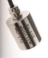 Ultra-Trak 750 Sensor.
Ultrasound provides early warnings which help prevent lubrication failures. It can identify previously unknown conditions quickly, provide an isolated source of sound and a large number of points can be taken in a short amount of time.
Taking an ultrasound reading is as quick as making contact and hitting the store button. Around 15-20 seconds are enough to create a sound file recording, and a little longer for slow speed bearings.
If a slow-speed bearing is good, not much will be heard ultrasonically because there are no fault conditions that would produce high frequency sound. If a fault starts to occur, every rotation, clicks, pops or screeching sounds would indicate metal/metal contact or damage that can be heard in headsets and on the recorded sound file and seen on the time waveform.
PREPARE TO BE SUCCESSFUL
Start an ultrasound program by prioritizing equipment based on an asset criticality list. A Plant Services Magazine article from June 2015 recommends implementing a successful predictive maintenance (PdM) program first to the top 20% of critical assets. After data has been gathered and failures are under control there, apply it to the next 20% of assets until 85% of the most critical assets are on some type of PdM program. Ultrasound is a great place to start; it’s easy to use and the most versatile monitoring technology.
Some equipment needs more frequent testing than others since some run 24/7 and some start and stop and run only as needed, on demand or as backup. Take more frequent readings on the equipment running most often.
Set up schedules using a criticality index based on factors such as the likelihood of breakdown, the consequence if it fails, cost to repair, etc. In some facilities, safety could be an issue if equipment fails. Some assets may have long lead times to get parts for repair, increasing their criticality.
CONSISTENCY AND REPEATABILITY
It is important to make ultrasound readings as repeatable as possible. The most important thing is to always make contact and test at the same location every single time. For consistency, touch each test point at the same angle. Compare similar bearings on each piece of equipment. Maintain the same frequency setting on the instrument, and confirm every diagnosis.
When inspecting bearings, it is important to make contact as close to the bearing as possible since sound attenuates or drops off the further the monitoring point is away from the source of the sound. Grease fittings are the perfect test point. Sound travels well there, since the grease tube acts like an extension of the stethoscope, extending the waveguide for sound. The only time it is not recommended to use grease fittings as contact points is if they extend out beyond a guard or cage far away from the bearing.
If there are no grease fittings at the fan or outboard end of a motor, it is common to make contact with one of the bolts that holds the fan shroud on. Avoid making contact with the shroud itself since it can pick up competing noise from the fan. Whatever is chosen, use the same point every time.
COMPARISON VS. HISTORICAL
First-time ultrasound users for condition monitoring commonly ask how to set baseline and alarm levels and how to know if what they are hearing is good or bad. When first starting up a program, the fastest way to get an idea of what condition the equipment is in or as a reference to how the equipment should sound is all about comparison. Compare the dB level at identical points. Use the software to overlay a FFT on the screen to compare baselines to current readings or compare up to four points on four identical machines.
Comparing is also the quickest way to determine if a reading is good or bad. Look at recordings of identical points on identical machines. It is important not to use what is heard in the headset as the baseline since sound is very subjective. What sounds good to one technician may not sound good to another. The sound file recordings tell the whole story. Faults and harmonics show up there. Playing sound file back in the software eliminates subjectivity.
Establish baselines using the historical method. First, acquire baseline sound sample data and upload it to the software to save. Record the dB level and sound files to be able to have more diagnostic information.
Next, build history by taking and saving more data points in the software more frequently at first. Review data from prior months and use this history set a baseline and alarm levels using delta values or failure mode standards. When levels are seen above the baseline, know what it means.
Use the ultrasound software to display the top view of the entire plant level and expand each application within the plant. In the Historical Method example shown, one application is bearings and there are three areas where data will be collected: heat treat, machine room 2015 and machine room. Within the machine room there are three pumps. On pump 1 there are four test points called Drive A-D. At each point there are six months of history, with bold indicating the baseline. The baseline can be changed at any time by highlighting the reading and editing on the record information tab. Decibel levels can be read on the screen at the right, and the software indicates there was a low level alarm in yellow on 5/20 and a high level alarm on 7/20.
Trend charts and point-specific reporting features can be integrated with sound files, infrared and digital images to create useful reports and documents. Multiple readings can be displayed along with baselines and high and low alarm levels. Trend charts also show temperature to see how temperature correlates to changes in the dB level. Features such as these make it easy during repair calls to get part replacements that need proper documentation.
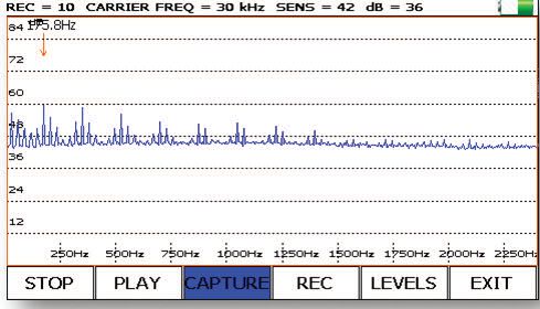
 Spectrum analysis software provides FFT view of recorded sound files from theme park problem Pump 4. Software has a bearing fault calculator integrated into it which calculates outer race, inner race, ball pass, and fault frequency. In this example, the highest peak can be seen at 175.8 Hz. ultrasound determined it to be an inner race failure, which was subsequently confirmed by vibration analysis.
ACTION LEVELS FOR ALARMS
Spectrum analysis software provides FFT view of recorded sound files from theme park problem Pump 4. Software has a bearing fault calculator integrated into it which calculates outer race, inner race, ball pass, and fault frequency. In this example, the highest peak can be seen at 175.8 Hz. ultrasound determined it to be an inner race failure, which was subsequently confirmed by vibration analysis.
ACTION LEVELS FOR ALARMS
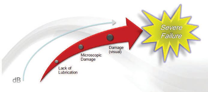
Set two levels of alarms based on how much the dB readings change as compared to the baseline. For bearings, the low and high alarms occur at a delta of 8 dB and 16 dB above the baseline. The low level alarm at 8 dB above the baseline indicates lack of lubrication. At this point there is no damage yet, but there is a uniform increase in friction and the bearings need lubrication.
The next stage of failure occurs at 16+ dB above the baseline. Under this high level condition for bearings, it indicates the point beyond lack of lubrication where damage has occurred. A facility could decide to change the damaged bearings, let them run, run vibration and/or more diagnostic tests, or take more ultrasound recordings and compare the baseline sound files to the alarm level sound file.
By the time readings reach 35+ dB above the baseline, bearings are at the onset of severe failures and are operating on borrowed time. They are much closer to the failure point F on the IPF curve, and can be heard in the audible range.
There are only two times that these alarm levels should be adjusted: for slow speed bearings and with variable frequency devices. On devices slower than 100 rpm, dB levels won’t be as high. Depending on the history and trends seen on the particular equipment, alarm levels may need to be lowered. Possibly set at 4dB for the low level alarm and 8dB for the high level alarm depending on what the trend shows.
Changes in speed in VFD equipment don’t affect ultrasound dB levels much. This is not the case with vibration testing where speed is very important. In applications where the swings in speed aren’t that wide, like in a device that runs at 1800 rpm one month and 1500 rpm the next, widen the alarm levels to 10 dB for the “low” alarm and 18 dB for the “high” alarm.
ANALYZING SOUNDS
There are several points to consider when using ultrasound as part of an equipment reliability program. Ultrasound is an early indicator, meaning that action doesn’t usually need to be taken immediately. It allows for time to make a proper decision. If the next reading shows an alarm, there could be cause for concern.
Slow speed levels may need lower alarm levels since slow speed bearings won’t make as much noise as higher speed bearings. Extremely slow speed bearings that are good produce very little ultrasonic noise. Failures in these types of bearings can be heard and viewed easily in recorded time-waveform views of ultrasounds.
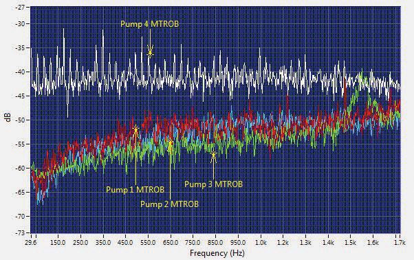
 Ultrasound collected on 4 of 8 new pumps at a theme park. Pumps 1-3 had no problems and Pump 4 sounded an obvious problem.
An invalid baseline presents itself quickly once historical data has been established. It will be easy to see if a baseline was set on a bad bearing. If a bearing is already bad and is failing, it will present a gradual upward trend when viewed with ultrasound.
When taking the initial baseline readings, apply grease to the bearing. If subsequent dB checks continue to rise, the bearing is in failure mode already and when it began to rise is unknown. If the dB level falls, it needed lubrication, and the new reading, including the sound file, is a good one to use as a baseline.
 Alarm levels.
ULTRASOUND ASSISTED LUBRICATION
Alarm levels.
ULTRASOUND ASSISTED LUBRICATION
Most premature bearing failures are lubrication related. Failures can be due to either over-lubricating, under-lubricating, using the wrong grease for the wrong application, mixing incompatible greases or simply lubricant contamination, pumping dirty grease into the bearings. The tendency is to over-lubricate bearings, too much and too often. Traditional lubrication programs are time-based, generating a PM for a particular piece of equipment specifying a certain number of pumps of grease on a certain frequency.
But there are many issues with time-based lubrication. How was the amount of grease determined? Is it too much? Does it actually need grease? How much? Is the time interval between lubricating correct? Good reliability programs move away from time-based and instead use condition-based lubrication approaches.
Ultrasound can be used as a listening tool to determine when enough grease has been applied to each bearing and when or if it has begun to be over-lubricated. Ultrasound listens for and displays the dB level of friction inside the bearings, so watching and listening while applying grease tells when to stop. With time-based programs, everything is greased, whether it needs it or not. With ultrasound, bearings are only greased when they need it.
Three things are expected when using ultrasound while greasing bearings. If the bearings need grease, the dB level will decrease as lubricant is applied. After an 8-10 dB drop, greasing can stop and the level won’t rise again.
If the bearing is already sufficiently lubricated, the dB level will start to increase while applying lubricant. Over-lubrication increases friction and pressure in the bearing and causes more noise. If it rises a few dB after only a couple pumps of grease, stop lubricating. Too much is being applied.
If there is no change in the dB level while greasing, further action should be taken to investigate why. The bearing may be in a failure mode that is beyond lack of lubrication or in a mode that lubrication doesn’t solve. It may indicate a broken bearing seal failure from previous over-lubrication where the grease isn’t being held in the bearing housing and instead is going into areas of the motor where it shouldn’t be.
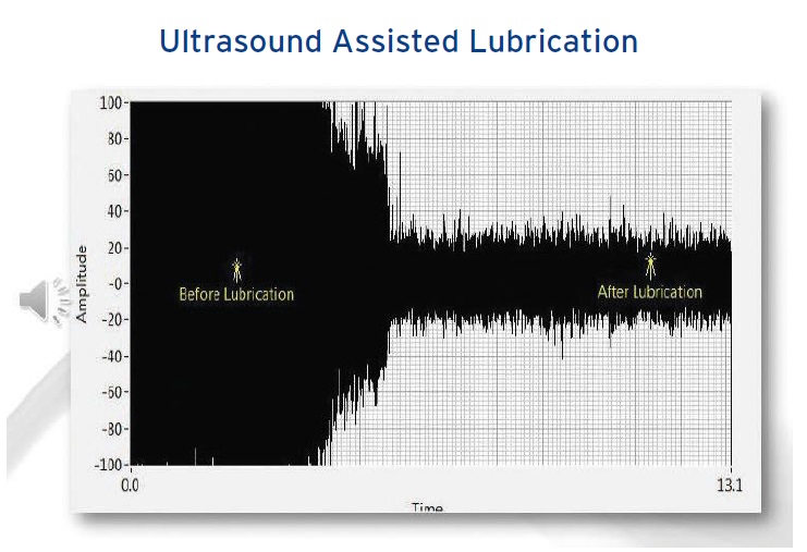
Before lubrication, the sound file or waveform shows a high or loud dB level. After lubrication with grease, the waveform dB level fell down to be steady and constant. At this point, the bearing is properly greased and lubrication should stop.
If, however, grease was continued to be applied, ultrasound can hear the increased pressure and friction inside the bearing housing. The amplitude on the waveform will increase, indicating that the bearing is over-lubricated.
A good lubrication scenario occurs when facilities lubricate equipment according to manufacturer’s recommendations and make sure to use the right grease for the right application by consulting with the lubricant supplier. They determine the lubrication frequency based on equipment runtime and operating conditions.
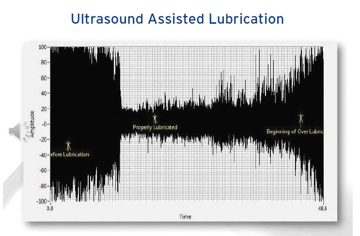
 The waveform trend when using ultrasound to properly lubricate a bearing, stopping when properly lubricated.
 The waveform trend when using ultrasound to properly lubricate a bearing, stopping when properly lubricated.
A better scenario for facilities that continue to use time-based lube PM’s is to implement an ultrasound instrument to listen to the bearings while applying lubricant. This will let the lubricator know when to stop applying grease, and other problems will be found.
The best scenario uses an ultrasound instrument with data collection capabilities to record both dB level and sound files and makes use of the historical method. Establish baselines and alarm levels. Once these levels are known, react only to the high or low alarm conditions. Only lubricate equipment with an ultrasound instrument when a data point is in the low alarm or lack of lubrication condition until the dB decreases back to baseline levels. On more critical assets, perform a follow-up inspection after lubricating to ensure that the dB levels remained at the baseline and record a new sound file to compare to the original baseline sound file.
A PART OF EQUIPMENT RELIABILITY PROGRAM
Using ultrasound for mechanical and condition monitoring is very easy to do. More than just a leak-detection technology, it’s used with multiple applications and is an effective complement to other technologies that a facility may already be using such as IR thermography or vibration analysis. The benefits to using ultrasound more than outweigh the costs of the instrument.
Debbie Sniderman is an engineer and CEO of VI Ventures, LLC, an engineering consulting company. You can reach her at info@vivllc.com.