20 Minutes With Colby Austin
Rachel Fowler, Associate Editor | TLT 20 Minutes April 2015
The engineering manager for Napoleon Engineering Services discusses the complexities of bearing testing and the advantages of source qualification inspections.
COLBY AUSTIN - The Quick File
Colby Austin is the engineering manager for the bearing inspection and testing departments at Napoleon Engineering Services (NES) in Olean, N.Y. He has been a team member at NES for four years where he held positions throughout the bearing inspection and testing departments and handled select projects in support of the custom bearing manufacturing department.
Colby holds a bachelor’s of science degree in mechanical engineering technology from Alfred State University in Alfred, N.Y.

Colby Austin
TLT: How did you get interested in rolling element bearings?
Austin: I was referred to NES by a friend who knew I was looking for a career in an engineering-intensive field. I began my career at NES about halfway through my junior year in college, of course, knowing very little about bearings. Like many consumers, I thought they were like any other simple machine element that required a handful of calculations out of a catalog to select and implement into a given application. I was quickly made aware of the complexities of rolling element bearings and all the tools one needs to design, manufacture, inspect and implement them successfully for a large range of applications. Because NES is involved in many areas of the bearing industry from mud slurry testing of agricultural bearings all the way to reverse engineering and the resulting manufacturing of custom product for aerospace applications, I have had the privilege of receiving a hands-on education over an accelerated time frame. This type of immersion into an engineering-intense field would interest any engineering mind.
TLT: What are your areas of expertise working in the bearing industry?
Austin: I’m hesitant to claim expertise in any area of the bearing industry at this early stage of my career, but bearing testing and inspection have become my areas of interest over the past few years. In order to correctly test and inspect bearings, one must really understand a variety of bearing-related topics including—but not limited to—bearing design practices, catalog calculations, international standards, manufacturing processes, material properties and characteristics, inspection equipment, analytical simulation software, lubrication, failure analysis, reliability statistics and all types of life testing equipment. Because I deal with a wide range of customers and applications with all levels of bearing knowledge, I am required to supply a packaged solution utilizing some or all of these areas of knowledge.
Most recently I’ve enjoyed being involved in the acceleration of our analytical simulation capabilities including finite element analysis and multiple quasi-static analysis programs specifically designed for rolling element bearings. With these additional capabilities combined with decades of in-house bearing knowledge, I can better quantify the effects of different bearing designs and the manufacturing capabilities in our source qualification programs, as well as offer application analysis in conjunction with endurance testing to evaluate the probability of success of an alternate bearing design in a specific application.
As many bearing manufacturers are expressly aware, head-to-head life testing of different bearing manufacturers can be unfair. Because we are dealing with short timelines and limited budgets, this testing is required to be performed under accelerated conditions in order to reduce testing time and cost. Each manufacturer has designed its bearing to optimally perform in a window of loading conditions often based on the needs of their target market. With our enhanced modeling capabilities, we attempt to find the overlap in these operating windows and use testing conditions that are confined within these windows. This scenario is not always possible as the operating windows may only overlap in very mild conditions, which may require years of testing to complete. Using a combination of analytical simulation and reliability statistics, we can alter the test plan to focus on relating the test data back to the application rather than a head-to-head test plan.
TLT: What areas of bearing modeling are beneficial to OEM design engineers?
Austin: Bearing modeling in general is invaluable to any OEM design engineer required to implement bearings. OEM engineers are constantly faced with the challenges of designing more efficient machines and reducing component costs all while continuing to meet or exceed customer expectations. From programs that make American Bearing Manufacturers Association and International Standards Organization standards quick and easy to execute, to quasi-static simulations and fully dynamic simulations, every level of modeling is a benefit in the pursuit of information that allows technical decision making possible. We are seeing more and more OEMs invest in this software and use NES to confirm calculations, supply the critical inspection characteristics needed for these programs and perform a wide variety of testing to validate their models (such as new material life adjustment factors). An OEM engineer correctly utilizing bearing modeling can begin to define what characteristics of a bearing are required to make their product successful in exceeding warranties, and more importantly, exceeding their customers’ expectations.
To assist OEMs that do not yet possess in-house bearing modeling, we’ve developed multiple value-added options to our standard inspection programs so that OEM engineers can benefit from these tools. As a team member at NES, I’m constantly challenged to use the tools available to bridge the gap between the OEM and the bearing manufacturers when it comes to bearing knowledge. Fully in-depth application analysis is not always a cost-effective solution to supplying the customer with enough information to make a decision (with the keyword being enough). Thus, I’ve developed a base level modeling option to estimate the maximum load to avoid edge loading for low-risk applications.
This analysis helps OEMs understand the limitations of a given bearing design to safely distribute load across the raceway and avoid the potentially catastrophic condition of stress concentration at the roller ends. We often see OEMs qualifying new suppliers through the Source Qualification Inspection (SQI) program, and the results show two suppliers that have achieved adequate manufacturing quality and have successfully conformed to the international standards of design. However, the two suppliers possess different internal geometries such as raceway and roller crowning profiles. Because the dynamic and static load rating calculations do not fully capture these geometries, the OEM may incorrectly make the conclusion that the new supplier will be successful in the application. The maximum load to avoid edge loading, as calculated by NES, quantifies these design differences and informs the OEM that one supplier will approach the undesirable condition of edge loading before the other. This process is the minimum value added option and requires a long list of assumptions, but it has proven to be valuable in communicating the potential effects of bearing design differences with customers that would otherwise ignore these differences.
For example, an OEM approached us recently to perform an SQI on relatively small-tapered roller bearing sets that are critical to their equipment. The original bearing manufacturer (a well-known tier one manufacturer we’ll refer to as Supplier A) had performed the necessary application engineering and chosen a part number that would cover the desired range of loading and speed conditions. Supplier A also was helpful in supplying the OEM with loading limits and some life expectancy numbers to help the OEM when performing application engineering for their equipment. The OEM found an alternate bearing manufacturer (an off-shore supplier we’ll refer to as Supplier B) that has adequate quality control in place and was offering a significant reduction in cost.
NES performed the SQI and found both suppliers met industrial standards as well as NES’s slightly more stringent standards for quality of workmanship and manufacturing capability. The dynamic and static load ratings were within 1% of each other as calculated by industrial standards. However, Supplier A possessed a raceway crowning on the order of 200-300 microinches while Supplier B had raceway crowning in the 50-100 microinch range. This obviously means that Supplier B will reach a catastrophic condition of stress truncation of the roller-to-race contact at much lower loads than Supplier A, but was it good enough for the application? To answer this, I suggested taking it a step further and perform an analysis to determine the maximum load to avoid edge loading. Under a range of loading conditions, NES would use a quasi-static stress analysis to calculate the stress at 101 points across the race-to-roller contact. Based on the level of stress concentration, I would categorize the manufacturer’s ability to distribute the given load safely into one of three categories (
see Figure 1):
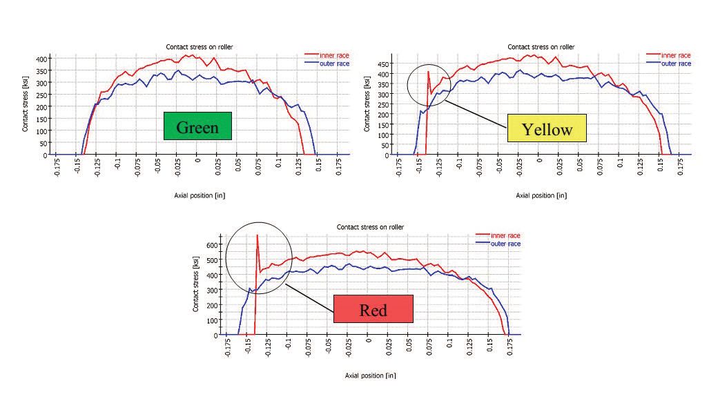 Figure 1. Three categories (green, yellow and red) of stress truncation.
Green:
Figure 1. Three categories (green, yellow and red) of stress truncation.
Green: Load is safely distributed and no stress concentration is experienced.
Yellow: Approaching a potentially catastrophic situation where stress concentration is present but the magnitude of the truncated stress is not the maximum stress experienced. This condition may be acceptable for short periods of time or for static load cases. (
Note: This condition should, of course, be avoided wherever possible, but NES found it applicable to separate this category from the following condition.)
Red: A likely nonacceptable condition where stress concentration has taken over as the maximum stress and infant failure may be a concern.
Supplier A was calculated to withstand 4,500 lbs. of pure radial load before experiencing edge loading, while Supplier B could only withstand 1,750 lbs., which would result in a 61% reduction in the allowable loads to be applied in the application (
see Figure 2 (
a and b)). As it turns out, Supplier A would safely meet the requirements for the OEM’s equipment and Supplier B would likely have caused warranty claims and disappointed customers. While this analysis only addresses one potential issue with the bearing design for the application, it is simply one extra tool to provide additional information in support of decision making in a source qualification endeavor. To those familiar with bearing design and calculations, this analysis is elementary and may require too many assumptions to be considered useful. However, there is still a large portion of end-users that aren’t familiar with these concepts. In those select situations, this analysis is a cost-effective way to communicate and quantify the design differences.
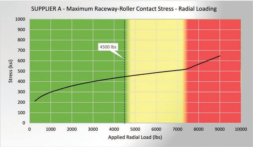
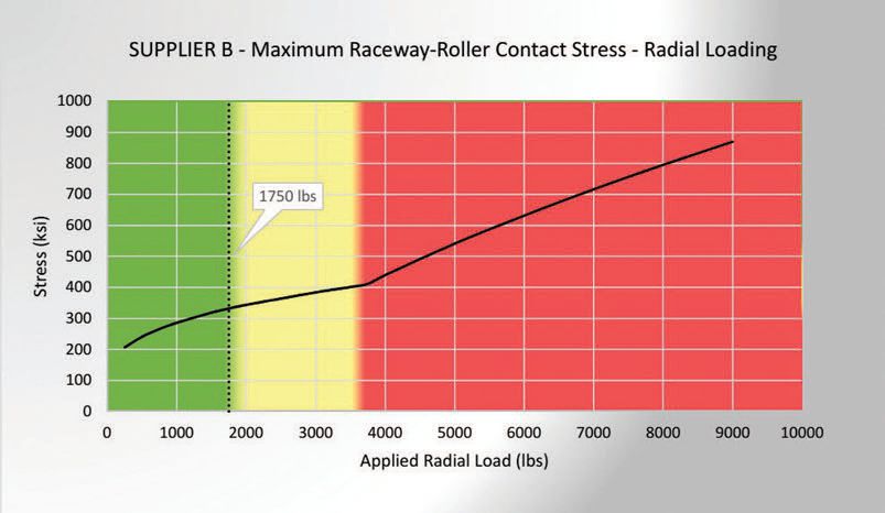 Figure 2 (a and b). Comparison of maximum load to avoid edge loading between Supplier A and Supplier B.
TLT: What advice would you give to young professionals interested in a career in this industry?
Austin:
Figure 2 (a and b). Comparison of maximum load to avoid edge loading between Supplier A and Supplier B.
TLT: What advice would you give to young professionals interested in a career in this industry?
Austin: The best advice I’ve received in my career is being encouraged to “make my own equations.” Most often I use this advice to create relationships between lab testing and field hours and it’s often in support of a decision-making criteria or acceptance criteria. As long as you understand the assumptions and there is quality technical information utilized, making your own equation encourages innovation and self-empowers an engineer to solve problems that aren’t explicitly outlined in the industry textbooks.
The top factor that has accelerated my learning and development in this industry is having an excellent mentor. In my observations, the bearing industry is unique in that while there is a wealth of technical information and engineering techniques that can be employed in decision making, there is still a large element of unknowns and assumptions that will never be fully captured. Thus, it’s necessary to pay attention to the decisions and conclusions made by your colleagues with years of experience in the industry in order to calibrate your own decisions (
see Figure 3). Find a good mentor who is willing to work closely with you, and if he or she doesn’t explicitly tell you to go away, you probably aren’t asking enough questions.
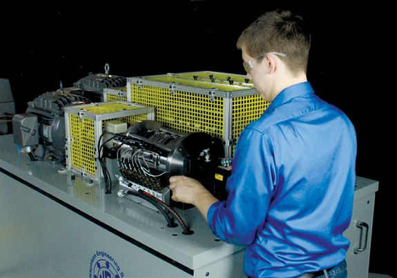 Figure 3. A young professional working in the bearing industry.
You can reach Colby Austin at caustin@nesbearings.com.