Lubricating wire ropes and chains
Jeanna Van Rensselar, Contributing Editor | TLT Webinars February 2015
An in-depth look at wear, maintenance and the unique requirements of these hard-working components.
KEY CONCEPTS
• Because of constant friction and abrasion in many applications, wire ropes and chains have unique lubrication requirements.
• The disadvantage of grease is it attracts particles in tight tolerance conditions. The disadvantage of oil is it might not remain in these highly dynamic applications.
• For chains, detergent additives are normally not necessary, but antifoam, antirust and film strength-improving additives are often beneficial.
MEET THE PRESENTER
This article is based on a Webinar originally presented by STLE University on May 14, 2014. “Wire Ropes and Chains: Wear Mechanisms & Means of Lubrication and Maintenance” is available at
www.stle.org: $39 to STLE members, $59 for all others.
Paul Conley has been chief engineer at SKF Industrial Market, Strategic Industries since 1997 and is a registered professional engineer in Missouri. He holds a bachelor’s of science degree in engineering from St. Louis University and a master’s of science degree in engineering from University of Missouri Science and Technology. He has published multiple papers in the field of lubrication and holds 15 patents with 12 pending. He is a contributing author to the STLE Handbook of Lubrication and Tribology and is a member of STLE, NLGI, ASTM and AISI. He can be reached at
paul.conley@skf.com.
Paul Conley
WIRE ROPES AND CHAINS ARE IMPORTANT MECHANISMS for transmitting tension loads requiring flexibility. As with many metal-to-metal contact systems where relative motion exists, wear is an important consideration.
Wire rope is comprised of continuous wire strands wound around a central core. When a wire rope bends around a sheave, drum or pulley, the individual wires and strands rub against each other in order to adjust themselves to the curvature of the rope wound around the core. Lubrication prevents wear on the individual wires and strands.
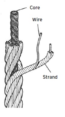 Wire-rope construction.
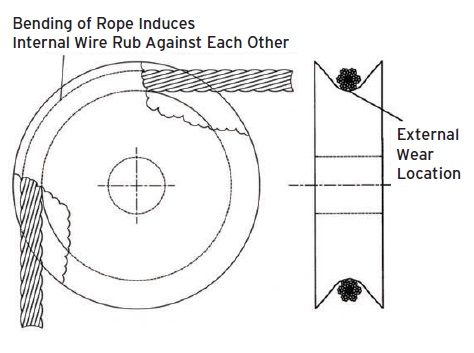 Internal and external wear locations.
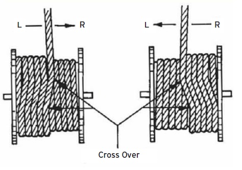 Crossover wear areas.
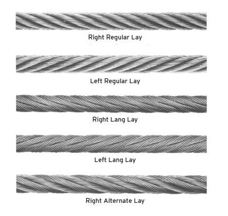
There are five basic classifications of wire-rope construction: right regular lay (the most common), left regular lay (the least common), right Lang lay, left Lang lay and right alternate lay. Lang lay tends toward longer life and durability but also greater fatigue due to the longer exposed length of its outer wires.
WIRE ROPE TERMINOLOGY
IWR: independent wire rope.
IWRC: independent wire rope core.
WCS: wire core strand.
FC: fiber core.
Seale (pronounced see-lay): parallel lay construction with same number of wires in each strand.
SFW: seale fiber wire.
WS: Warrington seale: parallel lay strand construction with alternating large and small wires.
FW: filler wire.
 Wire-rope construction configurations.
The primary factors in wire rope construction and material selection include:
1.
Overall strength and reserve strength
2.
Resistance to bending fatigue
3.
Resistance to vibration fatigue
4.
Resistance to abrasion
5.
Resistance to crushing.
For wire rope, wear and fatigue are the main failure mechanisms. Other sources of degradation include:
1.
Rope diameter reduction: the load’s elastic limits are exceeded
2.
External wear especially around a drum or sheath
3.
Internal wear due to constant repositioning as it turns around a radius
4.
Peening due to constant jostling and banging contact through pulleys
5.
Scrubbing: material displacement due to rubbing
6.
Broken wires/strands: tensile breaks in the outer strand of the rope require immediate replacement
7.
Corrosion.
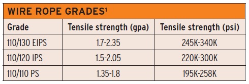 (EIPS = extra improved plowed steel; IPS = improved plowed steel; PS= plowed steel)
1. Per the Wire Rope Association.
(EIPS = extra improved plowed steel; IPS = improved plowed steel; PS= plowed steel)
1. Per the Wire Rope Association.
Because of all the stressors typical of wire ropes, standard design ratings include a safety factor of five (which would otherwise be considered high).
The application of oil/grease reduces wear by reducing friction and, in large bending applications, provides a film barrier between inner strands. The disadvantage of grease is that it attracts particles that can induce wear. The disadvantage of oil is that it may not remain on the rope as long as grease.
“The lab will start by determining the diameter of the wire rope. For an accelerated test, we would review the specs for the design load rating,” says STLE-member Paul Conley in a Webinar originally presented by STLE University on May 14, 2014. “And then we would design a sheave with a low diameter relative to the outer diameter of the rope. We would then use a chart to determine what kind of repeated loads and what kind of a strength reduction would result. We’d run a test to determine fatigue, then we’d run a baseline with rope to determine where the rope starts to fray and break. We are always most interested in the fatigue level.”
CHAINS AND THEIR APPLICATIONS
Chains are a series of journal bearings connected by link plates or sidebars (think bicycle chains). Loads are transmitted between links through a series of pins and bushings. Lubrication prevents metal-to-metal contact between those pins and bushings. Features unique to chains include:
•
Controlled flexibility in only one plane
•
Positive action over sprockets (no slippage)
•
The capacity to carry very high loads with negligible stretch
•
High efficiency
•
Flexibility between bearing surfaces (designed for wear resistance)
•
Smooth operation in adverse environments (elevated temperatures, moisture, foreign materials)
•
An unlimited shelf life (no deterioration due to age, sun, oil or grease).
There are 4 types of chains applications: drives for power transmission, conveyers, bucket elevators and tension linkages. In terms of how chains are manufactured, there are three types.
1. Roller chains. The major purpose of roller chains is to reduce friction. The same roller provides two functions: (1.) it engages the sprocket teeth and (2.) it transfers sliding action to the internal members of the chain (that are designated for that purpose). All roller chains are made up of two links—roller links and pin links—that are alternately spaced throughout the length of the chain. Two or more chains are jointed side by side by means of pins that maintain the alignment of the roller in various strands. In power transmission applications, the roller chain horsepower ranges from fractional to over 1,000.
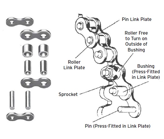 Chain schematic depicting components and assembly.
2. Silent chains.
Chain schematic depicting components and assembly.
2. Silent chains. Silent chains provide smooth and quiet operation at high speeds and tend toward long service life. They consist of a series of toothed linked plates assembled on a joint component so that articulating occurs between adjoining pitches. Four types of silent chains include:
a. Round pin with bushing. The joint components consist of a plain cylindrical pin with a bushing added to increase the bearing area of the chain joint.
b. Round pin and segmental bushing. Components include a plain cylindrical pin with segmented bushings. Each bushing covers less than half the circumference; lugs between the bushing segments prevent rotation in the links.
c. Rocker pin. When the chain flexes at the joint, differently shaped and keyed pins come into contact to generate a rocking motion between the pins.
d. Roller pin. The joint components include two pins with cylindrical surfaces that roll on each other.
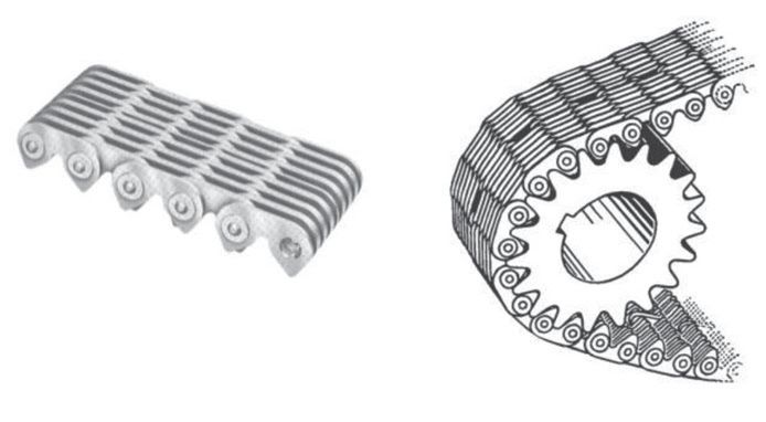 Basic chain operation.
3. Engineered steel chains.
Basic chain operation.
3. Engineered steel chains. These chains have the ability to bridge large spaces between parallel shafts. The chains are loaded very heavily but travel at slow speeds and are very rugged, with the toughness and elasticity to absorb heavy shock loads. Engineered chains are classified under ANSI standards and fall into one of the following five categories:
a. Straight sidebar chains with and without rollers. Straight sidebar chains with steel-fabricated rollers have steel bushings and pins and are assembled using interference fits between those parts and sidebars. The inside link, made of two sidebars and two bushings is called the
bushing link.
b. Offset sidebar steel chains. These come with and without rollers.
c. Bar line chains or steel block chains. These consist of two outer sidebars, one center bar and two pins making up a two-line section. Bar link chains do not usually have bushings.
d. Welded steel chains. These are similar to fabricated steel chains except that the links are integrally welded rather than being held together by tight fits and locking surfaces.
e. Open-barrel steel pintle chains. This type of chain is an economical, lightweight conveyer chain with fixed pins preventing rotation by means of mechanical locks or interference fits.
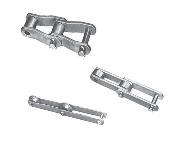 Three types of chain-link configurations.
WEAR MECHANISM AND LUBRICATION
Three types of chain-link configurations.
WEAR MECHANISM AND LUBRICATION
Wear is defined as a loss of material due to the chain components working either against each other or against some foreign material. The three most common types of wear are abrasion wear, adhesive wear and fatigue wear. The actual amount of wear on a given chain depends on several factors including:
•
The materials and heat treatment of the chain components
•
Load and speed
•
Lubrication
•
The presence of abrasive and corrosive substances
•
The configuration of the sprockets.
Most sliding or dragging chains have wear on the edges of the sidebars and often on the outer surfaces of the rollerless chain bushings. In drive and elevator applications, wear in the chain joints is usually the limiting factor in the life of the chain. In bushed rollerless chains, wear is caused by the movement of the pins in the bushings and by the bushings rubbing on the sprocket teeth.
In engineering steel chains with rollers, wear occurs on the outside diameter of the rollers, between the rollers and bushings and between the pins and bushings. Wear between the pin and bushing causes the chain to elongate (grow longer but not stretch) until the chain will not fit the sprockets correctly or will not maintain correct spacing or timing (the point at which a bicycle chain will fall off). Chain-wear elongation usually progresses through three stages:
1. First, there is a short period of rapid initial or run-in wear. In this stage, high spots wear off the pins and bushings and minor misalignments are quickly worn away.
2. In the second stage, there is gradual wear of the surfaces between the pins and bushings. In this stage, the pins are seated properly in the bushings and the bearing areas are normally well lubricated.
3. In the third stage, there is another period of rapid wear. As clearance between the pin and bushing gets larger, lubrication becomes less effective—to the degree that the case hardening of the pins and bushings may wear through, leaving a softer metal that will wear more dramatically. The result of excessive elongation on the sprocket may cause loads on individual joints to increase dramatically.
Since a chain must articulate over a sprocket, wear occurring between the chain bushings and the pins can cause elongation of the chain or lengthening of the pitch. Sprockets are designed to accept a reasonable amount of elongation from wear (three to six percent for many types), but when the chain elongates beyond this point it no longer fits the sprockets and the system will not operate properly. Chain wear elongation can be reduced by:
•
Selecting a chain with reduced bearing pressure between the pins and bushings
•
Selecting a chain with increased hardness of the chain joint members
•
Improved lubrication
•
Increasing sprocket size by increasing the number of teeth in the sprocket.
LUBRICATION AND MAINTENANCE
Each joint in a roller chain is a journal bearing, so it is essential that it receives proper lubricant to achieve maximum wear life. Some low-speed roller chain drives operate successfully with only the initial factory lubrication. However, most roller chain drives must be either periodically or continuously relubricated to obtain their full potential service life. In addition to resisting wear between the pins and bushings, an adequate flow of lubricant:
•
Facilitates the engagement of the chain rollers with the sprocket
•
Cushions roller to sprocket impacts
•
Dissipates heat
•
Flushes away wear debris and foreign materials
•
Retards rust.
LUBRICANT FLOW AND CHARACTERISTICS
Lubrication of the pin and bushing surfaces, which articulate under load, is most important, but some lubrication between the roller and bushing also is necessary. The lubricant should be applied to the upper edges of the link plates in the lower span of the chain shortly before the chain engages a sprocket. Then gravity and centrifugal force both will aid in carrying the lubricant to the critical pin and bushing surfaces. Surplus lubricant spilling over the link plate edges will supply the roller and bushing surfaces.
Lubricants for roller chain drives should have the following characteristics:
•
Sufficiently low viscosity to penetrate into the critical internal surfaces
•
Sufficiently high viscosity, or appropriate additives, to maintain the lubricating film under the prevailing bearing pressures
•
Clean and free of contamination
•
Capability of maintaining lubricating qualities under prevailing operating conditions.
These requirements are usually met by a good grade of non-detergent petroleum base oil. Detergents normally are not necessary, but antifoam, antirust and film strength-improving additives often are beneficial.
Avoid low-grade or impure oils. Low-grade oils cannot provide effective lubrication, and impurities such as acids or abrasives in the oil can damage the chain beyond repair. Heavy oils or greases should not be used because they are too thick to penetrate into the internal surfaces of the chain.
Conley says, “For chain lubricants the most important tests are the viscosity, temperature range and lubricant type. Anything beyond that involves additives. Aspects that I would focus on are any type of corrosion and oxidation additives and EP additives for heavier chains where the loads are significant.”
Wire ropes and metal chains are hard-working components that are critical to many industrial applications. With thorough maintenance and a good lubricant, they are a reliable means for transmitting significant power between mechanisms.
 Jeanna Van Rensselar heads her own communication/public relations firm, Smart PR Communications, in Naperville, Ill. You can reach her at jeanna@smartprcommunications.com
.