The power of aircraft hydraulic redundancy systems
Jean Van Rensselar, Contributing Editor | TLT Cover Story June 2013
They’re why today’s aircraft rarely crash—but surprising flaws reside in the system.
KEY CONCEPTS
• A major contributor to today’s safer aircraft are redundant hydraulic systems incorporating two or more subsystems.
• An aircraft’s flight control system relies heavily on fluid power in order to land the plane safely.
• The theory of redundancy has significant flaws that can have dire consequences.
In November 2010, a Qantas Airbus A380-842 was flying from Singapore to Sydney, Australia, with 440 passengers and 26 crew members. About six minutes into the flight, just as it was climbing out of Singapore over the Indonesian island of Batam, passengers heard a loud bang as a rotor disc exploded, spraying metal into the No. 2 engine. One of the shards jettisoned into a wing and severed the hydraulic line, which caused the hydraulic circuit to lose its fluid. The event was so spectacular that debris with the Qantas logo cascaded onto a road in the urban area below.
Barely missing a beat, the Airbus dumped its fuel, returned to Singapore and landed safely with its hydraulic control system intact—slats retracted, flaps extended and gear doors open. Despite what could have been a horrific event, there were no injuries onboard or on the ground.
The hydraulic and electrical systems were both backed up with redundant systems.
Not all stories end as happily, of course. In July 1996, just outside Long Island, N.Y., and about 12 minutes into the flight, TWA 800 (a Boeing 747) suddenly exploded. Immediately, the cockpit and most of the first-class section tore away from the fuselage and plummeted 13,000 feet into the Atlantic Ocean. The rest of the fuselage, under its own momentum, stayed suspended in mid-air for 30 terrifying seconds—with fully conscious passengers screaming and praying—before it suddenly shifted and dove into the dark, icy water. Of the 230 passengers and crew, there were no survivors. The investigation concluded that a spark (probably caused by corrosion of the aircraft’s aging wiring) had ignited volatile fuel vapors in the central fuel tank.
This highlights the downside of redundancy. It doesn’t always allow for the fact that failures rarely occur in isolation and, in actuality, have a tendency to propagate across multiple systems. It’s a stark illustration that not all failures can be mitigated by redundancy and that redundancy can create a false sense of infallibility. More on this later.
REDUNDANCY
Something is redundant if it contains a backup to perform its functions in the event it fails, and the backup is capable of carrying the load alone. A system is redundant if it has redundant parts.
Redundancy was first introduced as a design solution for reliability in complex tightly coupled systems by Jon von Neumann in his (still relevant) 1956 work: Probabilistic Logics and Synthesis of Reliable Organisms from Unreliable Components. Von Neumann was not interested in duplicating elements for their own sake but, rather, designing a system that would know when it needed to engage backup components.

Jon von Neumann
His first challenge was to build a reliable working computer from thousands of unreliable vacuum tubes. Over the course of the project, von Neumann made the groundbreaking discovery that a redundant system could be more reliable than its constituent parts. He wrote: “The basic idea in this procedure is very simple. Instead of running the incoming data into a single machine, the same information is simultaneously fed into a number of identical machines, and the result that comes out of a majority of these machines is assumed to be true. …this technique can be used to control error (1).”
He first introduced this concept when military equipment was still unreliable, and engineers were unable to satisfactorily increase dependability by continually increasing the reliability of individual components. Von Neumann was the first to demonstrate the significant benefit of creating a system that would automatically compensate for its own shortcomings—already prevalent in nature (two kidneys, cross-brain functioning, etc.) but not in design and engineering.
Now, 57 years later, because of von Neumann, the Federal Aviation Administration (FAA) can require verification that every safety-critical element of a civil airplane has no more than one failure in a billion hours of use.
BASICS
As aircraft performance increased in the 1950s, the amount of force required to operate mechanical flight controls required hydraulic systems to reduce pilot effort.
In general, current hydraulic designs have a dedicated system that supplies the primary flight control system (ailerons, elevators and rudders) while separate hydraulic systems provide secondary controls and utility functions (flaps, slats, landing gear, nose wheel steering, brakes, etc.).
The hydraulic actuators are controlled by valves. The actuators are operated directly by input from the air crew or by computers obeying control laws (fly-by-wire). Hydraulic power also can be stored in accumulators to start an auxiliary power unit capable of self-starting the aircraft’s main engines.
In commercial aircraft, the hydraulic power comes from electrically driven pumps. But even if all the engines fail in flight, the pilot can still engage the propeller-driven Ram Air Turbine (RAT) electric generator concealed under the fuselage. This provides emergency electrical power for the hydraulic pumps and control systems.
Today’s aircraft have hydraulic systems within a fly-by-wire design. FBW uses an electronic interface instead of manual flight controls, converting flight controls to electronic signals transmitted via wire. Flight control computers not only send information to the pilots to let them know how to correctly maneuver the actuators, they also transmit automatic signals that perform functions without the pilot’s input (especially important for stabilizers).
“Most modern military aircraft utilize hydraulic systems controlled by fly-by-wire systems,” explains Kenneth (Ed) Binns, senior research engineer, University of Dayton Research Institute in Dayton, Ohio. “For flight critical functions, they are required to have two-failure operational capability. In other words, two failures can occur and the flight controls will still allow safe flight. This is achieved by multiple primary hydraulic systems plus emergency backup systems powered by other power sources.”
With the current focus on decreasing the weight of aircraft as much as possible, high-power density (power/weight ratio) systems and subsystems are necessary. The easiest way to increase the power density in a hydraulic system is to raise the pressure, which today’s stainless steel and titanium hydraulic systems can accommodate to a degree (aluminum hydraulic components will fatigue—leak, fail, blow up—when system pressure exceeds 3,000 psi).
Henry Harschburger, a consultant on flight control systems design and development (and a widely acknowledged expert on military aircraft hydraulics), says, “The redundancy of flight controls and the associated hydraulic systems is a very complex subject. There are many hydraulic system arrangements and a number of power sources such as aircraft-engine-driven pumps and electrical-motor-driven pumps. The hydraulic system architecture is dependent on a number of factors— the aircraft configuration, the number of control effectors, power sources, reliability, survivability and safety requirements.”
THE BASIC AIRCRAFT HYDRAULIC SYSTEM
While each aircraft hydraulic system is a little different, a basic system consists of a reservoir, electric or engine-driven pump, a fluid filter, a relief valve to relieve excess pressure and multiple electrohydraulic actuators. The pump provides flow to meet the demands of the various actuators. The actuators are controlled by electrohydraulic servo valves (most flight control systems have tandem valves and actuators for redundancy purposes). The relief valve provides over-pressurization protection for the system.
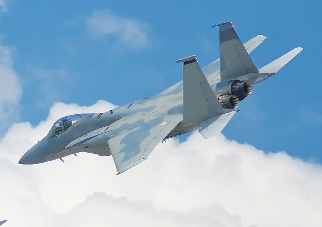
F-15
Harschburger explains that when it comes to hydraulics, there are two major differences between military and commercial aircraft: (1.) Commercial aircraft use nonflammable phosphate ester-based hydraulic fluid and (2.) The FAA Federal Acquisition Regulations (FAR) that affect the system architecture are different. Otherwise, most of the structural design requirements for the various system components are the same.
While the hydraulic control system varies greatly between aircraft designs, the F-15 control system is representative. The McDonnell Douglas F-15 was designed in the late 1960s to replace the F-4 Phantom and is still an effective military fighter. It is a relatively large, two-engine aircraft that has eight individual fuel tanks with a total capacity of 1,790 gallons located across the wings and the center of the fuselage.
The definition of redundancy, the F-15 has three separate hydraulic systems that can detect and isolate leaks in their associated subsystems. Each hydraulic system can also sustain the flight control system alone because each system has a switchover valve that senses system return pressure. If pressure falls below a set value, control is switched to another system, which should restore pressure.
In addition, there is an automatic control augmentation system that uses electric signals and servos to control the plane. The system also has sensors that continuously monitor aircraft rates (pitch, roll and yaw) and vertical and lateral accelerations. It uses the data to calculate the correct settings for the control surfaces according to speed and G-force. Whenever the pilot executes a command, the plane automatically compares the systems. If the difference between them exceeds a set range, the automatic control augmentation system disengages, allowing the conventional hydraulic system to do the work alone. The plane can be safely operated and landed after a total loss of any two of the three hydraulic systems.
HYDRAULIC AIRCRAFT FLUIDS
No aircraft, no matter how many redundant systems it has, can operate at peak performance without the specified hydraulic fluid—clean and uncontaminated. Considering the fact that redundant systems in a single aircraft generally use the same fluid, a compromise in fluid properties will affect all systems.
Today, most large commercial aircraft operate with phosphate ester aviation grade hydraulic fluid. Akyl and aryl phosphate ester base oils are the major constituents of this fluid. They will eventually become unstable and are susceptible to degradation. In addition, these oils will almost certainly be contaminated with solid debris, engine oil, cleaning solvent and/or water. Once degraded to a certain level, they will damage or destroy hydraulic system components. Alkyl phosphate esters are made from alcohols and aryl phosphate esters are made from phenol or alkyl phenols. Each degrades in a different way. (see the Sidebar—Three Ways Phosphate Esters Degrade).
THREE WAYS PHOSPHATE ESTERS DEGRADE*
Phosphate esters degrade in three ways. Each avenue becomes significant in certain environmental conditions that aircraft hydraulic systems are exposed to. All three paths produce acid phosphate (phosphoric acid derivatives) as the destructive degradation product.
1. Pyrolysis. Pyrolysis or thermal degradation of phosphate esters only becomes significant at very high temperatures above 300 F (150 C), which would be unusual in aviation hydraulic systems. It would probably only happen in the case of equipment malfunction or a few special situations such as brake system cylinders where the fluid is not sufficiently insulated to withstand the high temperature of carbon brakes. During pyrolysis, alkyl phosphate esters form unsaturated hydrocarbons and leave a highly acidic residue. Aryl groups are more resistant to pyrolysis.
2. Oxidation. Because phosphate esters are highly resistant to oxidation and aircraft hydraulic systems are closed systems with limited availability of ambient oxygen, oxidation is not a significant degradation path for hydraulic aircraft fluids.
3. Hydrolysis (reaction with water). The most common way that hydraulic aircraft fluids degrade is through exposure to water. This is due to the fact that hydrolysis occurs even at moderate temperatures (and faster at higher temperatures). Phosphate esters absorb water from the atmosphere very rapidly. Because of this, the hydraulic fluid normally contains 1,000s of parts per million of water capable of decomposing the fluid. Aryl phosphates are more prone to hydrolytic degradation than alkyl phosphates, as are alky and aryl-mixed phosphates.
All three types of degradation increase as the temperature increases. Oxidation and hydrolysis are also exacerbated by metals such as iron and copper. The harmful byproduct is always a phosphoric acid derivative—an acid so strong that it can damage hydraulic system components, attack and degrade elastic polymers and etch metal parts so badly that they fail.
* From here.
FLAMMABILITY (2)
There are currently four different hydraulic fluids used in aviation—of which the military and some small commercial aircraft use three. They are MIL-PRF-5606, MIL-PRF-83282 and MIL-PRF-87257. Only MIL-PRF-83282 and MIL-PRF-87257 are considered fire-resistant. They are both synthetic hydrocarbon-based. “Both of these fire-resistant hydraulic fluids have significantly reduced (by about 95 percent) hydraulic fluid fire damage in military aircraft,” says STLE-member Carl (Ed) Snyder, lubricants and hydraulic fluids materials engineer, University of Dayton Research Institute, Nonstructural Materials Division.
“MIL-PRF-5606 (not fire-resistant) is naphthenic mineral oil-based. Most military aircraft have converted from the flammable MIL-PRF-5606 hydraulic fluid to the fire-resistant fluids. Those fire-resistant fluids are completely compatible with the materials and design of hydraulic systems that were originally designed for MILPRF- 5606,” Snyder explains. “The conversion is very simple and, in most cases, is accomplished by merely topping off the hydraulic system of the aircraft that had been using MILPRF- 5606 with either MIL-PRF-83282 or MIL-PRF-87257.”
The fourth hydraulic aviation fluid is commonly used in large commercial aircraft and was designed for that specific application. It is a phosphate ester- based fluid that has excellent fire resistance but is different enough chemically to prevent direct substitution for MIL-PRF-5606, MIL-PRF- 83282 or MIL-PRF-87257. “The hydraulic system design and materials took into account the chemistry and properties of the phosphate ester hydraulic fluid,” says Snyder.
Even though airplanes carry thousands of gallons of highly flammable fuel, the importance of fire-resistant hydraulic fluid cannot be overstated. There is a significant difference between hydraulic fluid and fuel in both the location and pressure. First, hydraulic fluids are used in systems that are at very high pressures, up to 5,000 psi. This means that when there is a leak in a hydraulic system, the fluid is usually sprayed in a mist (a very flammable form) (3). Fuel systems are under much lower pressures and, therefore, any leaks are not typically in a mist form and are more difficult to ignite.
A more significant issue is the location of the hydraulic fluid compared to the fuel. The hydraulic system is located throughout the aircraft, from the tip of the nose (in the nose wheel steering) to the tail (in the rudder hydraulic system).
“Most of the military hydraulic fluid fires occur in high hazard areas where fuel is not located,” Snyder says. “For example, there are a lot of hydraulic brake fires because applying the brakes generates significant heat in the brake area. The hydraulic fluid is pressurizing the brake system. If a leak occurs, the fluid sprays on the hot brake and ignites.”
Another significant source of hydraulic fires is shorted electrical lines burning holes in adjacent hydraulic lines and then igniting the hydraulic fluid—fuel is not located in either of these hazardous areas.
Fluid flammability is a complex issue. If the fluid is contained in the hydraulic system, there is little oxygen present and so the hydraulic fluids will not burn. The problem occurs if the hydraulic system has a leak—air and the hydraulic fluid could get to a point where they can combust. If the highly flammable MIL-PRF-5606 fluid is exposed to a spark or other ignition source and air, the fluid will likely catch fire and burn at normal operational temperatures. The newer fluids, MIL-PRF-87257, MIL-PRF-83282 and phosphate esters, are used below their flash points, so if exposed to an ignition source and air, they will not catch fire and will prevent the spread of fire.
“Another flammability issue is the problem with the fluids burning and the fire spreading to the fuel, which is obviously very combustible and will likely result in a loss of the aircraft,” says STLE-member Lois Gschwender, senior research materials engineer, University of Dayton Research Institute, Nonstructural Materials Division. “Compared to MIL-PRF-5606, MIL-PRF-87257 and MIL-PRF-83282 have very low energy flames that travel very slowly. Phosphate esters will not even sustain a fire and will self-extinguish. The fire-resistant fluids are much safer because they ignite at much higher temperatures than MILPRF- 5606 and once they ignite, the fire is much less likely to spread.”
CONTROLLING THE ACID IN PHOSPHATE ESTER-BASED HYDRAULIC FLUID*
Acid control additives (epoxides) were developed in the late 1960s. These additives react even at normal ambient temperatures to neutralize the damaging phosphoric acid derivatives. This keeps the aircraft’s hydraulic system free of strong acids until the acid control additives are nearly depleted. The issue is that the allowable amount of acid control additive is limited because of crucially important seal swell and flammability considerations.
Even though all commercial aviation hydraulic fluids are comprised of phosphate esters and they all contain essentially the same amount of additive, they are not equally stable.** This is because of differences in the resistance of the base oil constituents to hydrolysis. Also, supplementary additives can be used to slow down the rate of hydrolysis.
Water levels that exceed the capacity of the acid control additive are not uncommon. For example, most aircraft manufacturers allow operation with up to 0.8 percent water in the hydraulic system. This is based on the assumption that strong acidity will not occur before the next fluid maintenance due to routine makeup with new fluid and the typically low hydrolysis rate at the moderate temperatures aircraft hydraulic systems are exposed to.
To protect against damage from high acidity, aircraft manufacturers typically recommend a maximum acid number of 1.5, beyond which the fluid should be replaced. Serious damage would start occurring at acid numbers above 5, so the acid number limit of 1.5 provides a significant safety cushion against aircraft system damage.
In addition to the highly damaging acid, most aircraft hydraulic fluids also contain weak acids (i.e., carboxylic). In fact, acidity measured in aircraft hydraulic systems with acid numbers below 1.5 is usually caused by weak acids that are not neutralized by acid control additives (they can also be a byproduct of the additives themselves). These weak acids are fairly innocuous.
* With the exception of MIL-PRF-5606, military hydraulic fluids do not degrade under normal operating conditions. In fact, they can operate indefinitely if contaminants can be removed.
** Most small private aircraft use MIL-PRF-5605 and many small commercial aircraft use MIL-PRF-87257.
REDUNDANCY’S DARK SIDE
In July 1989, the tail-mounted engine of a United Airlines DC-10 (Flight 232) carrying 285 passengers exploded. The redundancy system included two wing-mounted engines that still had plenty of thrust—so in theory everything should have ended happily. However, shrapnel from the explosion tore into the fuselage, severing all three of the triple redundant hydraulic systems and rendering the airplane uncontrollable. This happened even though McDonnell Douglas designed this and every other DC-10 to resist shrapnel, each of the hydraulic systems had its own redundant pumps connected to redundant (and differently- designed) power sources with redundant reservoirs of hydraulic fluid. Therefore, nearly all aviation experts considered a triple hydraulic failure unequivocally impossible. Some experts say that the aviation industry had been misled by redundancy, and this is a good example.
According to John Downer in his 2009 article “When Failure is an Option: Redundancy, Reliability and Regulation in Complex Technical Systems,” there are four basic flaws in assumptions about the reliability of redundancy (4).
1. Complexity. Increasing redundancy can increase complexity to the point where the redundant system itself becomes the primary source of unreliability. To get around this, most contemporary redundant systems have a central management system—which again creates a single point of failure. As Downer puts it, “a centralized redundancy management function will likely inherit the criticality level of the most critical task that it supports.”
He uses this example: In January 1989 a British Midland 737-400 crashed at Kegworth, England, killing 44 people. Accident investigators believe that one of the aircraft’s two redundant engines caught fire and workers had miswired the (not redundant) warning system. This led the pilot to shut down the wrong engine.
2. Independence. Many calculations assume that redundant systems behave completely independently of each other. Two elements are independent if the chance of one failing is not linked to the chance of the other failing. Downer says this is a fallacy for a number of reasons, one being that identical elements operating simultaneously are apt to wear in similar ways and, thus, fail at similar times. Also, most failures result from the environment acting on the entire system (redundant systems in aircraft are generally exposed to the same operating environment). In addition to the aircraft’s internal operating environment, consider that a violent storm, cloud of ash or flock of birds have the potential to stress all redundant elements in a system simultaneously.
3. Propagation. Failures have a tendency to propagate. The majority of fatal accidents involve an unanticipated chain of failures, where the failure of one element propagates to others in what the National Transportation Safety Board (NTSB) refers to as a cascade. This means that an accurate measure of reliability from redundancy needs to account not only for the independence between redundant elements but also for the independence of these elements from other elements that are functionally unrelated. Considering that, as happened with United Flight 232 mentioned above, a failed engine could fatally damage the rest of the aircraft—four engines are actually less safe than two engines in some regards. Downer says that Boeing has come to this very conclusion, figuring that because of the lower risk of one engine failing catastrophically, its 777 is safer with two engines.
4. Human elements. Redundant systems require people to build and work them. The NTSB estimates that 43 percent of fatal accidents involving commercial aircraft are caused by pilot error. A surprisingly large percentage results from pilots misreading navigational instruments and flying the plane into the ground.
For example, on Dec. 29, 1972, just outside Miami, Fla., the crew of Eastern Airlines Flight 401 became so fixated on a faulty landing gear light that they failed to notice the autopilot was disengaged. They continued in their distraction until the aircraft smashed into the Florida Everglades, killing 101 of the 176 passengers.
Seemingly redundant and isolated, elements are frequently linked to each other through the people who operate and maintain them. A relatively common mistake is when the pilot responds to an engine failure by shutting down the wrong engine—an ominous error in a twin-engine aircraft.
Human reliability problems are sometimes mitigated through human redundancy. For example, commercial aircraft have two pilots, and the U.S. Navy creates a navigational safety net by distributing knowledge among the navigation team and encouraging mutual monitoring and assistance.
Downer concludes that these four reasons do not make redundancy an ineffective engineering tool, but, rather, that engineers need to be mindful of its limitations. Downer says that the key to a reliable design is thorough human understanding, rather than advanced materials and manufacturing processes, computer controls and/or feedback loops.
FINALLY...
An astonishing example of just how well a thoroughly designed redundancy system works involves a midair collision that occurred on May 1, 1983. During an Israeli Air Force air combat training session, an F-15 collided with an A-4. The pilot of the A-4 ejected just before his aircraft disintegrated. The right wing of the F-15 was cleanly sheared off about two feet from the fuselage. The crew realized that they were in dire straits, but because of smoke billowing out of the plane were unaware that the wing was gone. Seconds later, the F-15 began an uncontrollable spin. Rather than eject, the pilot tried to recover stability by engaging the afterburner to increase speed. Seconds later the aircraft righted itself and began a controlled descent. The tower diverted the plane to a nearby airbase for landing, but in order to maintain the necessary lift the pilot had to hit the runway at twice the usual speed. In fact, the F-15 was going so fast that its tailhook tore off (5). The pilot finally brought the plane to a stop 20 feet before the end of the runway. Everyone survived, including the F-15, which was repaired and redeployed.
www.canstockphoto.com
This seeming miracle occurred because of F-15 design factors such as a high thrust-to-weight ratio, a wide body, a lift-producing fuselage and, most important, redundant hydraulic controls. An actual video of the entire episode is posted on YouTube (6).
“Safety and reliability concerns have been of high importance for hydraulic systems since they were first used in aircraft. The requirements and technology for isolating failures have evolved over the years and the safety of aircraft hydraulics is extremely high,” Binns concludes.
Harschburger adds, “The bottom line is that redundant hydraulic systems allow an aircraft to survive catastrophic failures or accidents.”
REFERENCES
1. From here.
2. Based on information supplied by Carl (Ed) Snyder and Lois Gschwender.
3. Per Kenneth Binns: Technically advanced dual-actuator seals greatly reduce external leakage.
4. From here.
5. The tailhook is used to achieve rapid deceleration during abrupt landings. As the aircraft approaches the runway, the pilot lowers the hook so that it will just contact the ground when the aircraft wheels touch down. The hook then drags along the surface until it engages with the arresting cable stretched across the runway.
6. Click here.

Jean Van Rensselar heads her own communications firm, Smart PR Communications, in Naperville, Ill. You can reach her at jean@smartprcommunications.com.