What Is EHD?
Dr. Lavern D. Wedeven | TLT Technical Analysis November 2012
Examining the concepts involved in hydrodynamic lubrication is fundamental to our understanding of elastohydrodynamics.
www.canstockphoto.com
KEY CONCEPTS
•
The success of a lubrication system in a machine relies on the performance of many mechanisms of lubrication.
•
The most dominant feature of elastohydrodynamic lubrication is the Hertzian condition of contact.
•
The conjunction zone of a typical EHD contact is divided into three general regions.
Editor’s Note: The life of many highly-loaded machine elements relies on the formation of a very thin elastohydrodynamic (EHD) oil film between surfaces in motion. Its formation results from the combination of a remarkable set of circumstances rarely appreciated. This article endeavors to explain the mechanism of elastohydrodynamic lubrication with simple physical concepts that are easy to understand.
THE LUBRICATION OF RUBBING SURFACES IN MACHINES is accomplished by separating them or protecting them in some way so that detrimental effects of high wear or high friction can be eliminated. This is generally achieved by the formation of a film of material between the surfaces in motion. This film carries the load and bears the shear between the surfaces. These lubricating films are formed by many mechanisms of lubrication, which fall under the general classifications of boundary, hydrodynamic and EHD. Some of these mechanisms rely on the chemical properties of the lubricant and its additives, while others rely more on the physical properties such as viscosity. Thus, the lubricating film may be of a liquid nature produced by the generation of hydrodynamic pressure or it may be of a solid nature as the result of adsorption or chemical reactions at the solid surfaces.
In general, the success of a lubrication system in a machine relies on the performance of many mechanisms of lubrication. The lubrication system is like a team whose success depends on the performance of the individual players. Each mechanism of lubrication has a task to perform, and the overall success depends on the team effort.
The objective of this article is to describe the mechanism of EHD lubrication. The subject of elastohydrodynamics has been around since the early 1950s. Unfortunately, the literature has not always been very helpful in examining what EHD really is. Its real meaning is frequently obscured by differential equations and computer solutions.
The mechanism of EHD lubrication is basically quite simple and really doesn’t deserve such a long name. It is essentially an extension of ordinary hydrodynamic lubrication, which was described by Osborne Reynolds back in 1886 (
1). The concepts involved in hydrodynamic lubrication are fundamental to the understanding of elastohydrodynamics, and this is where we begin.
VISCOUS FLOW, PARALLEL SURFACES
First, consider the flow of fluid between two parallel surfaces, as shown in Figure 1. The fluid molecules adjacent to the solid surfaces adsorb* or stick to it. Thus, the molecules on the bottom surface move with it at a velocity u; and, the molecules on the top surface remain stationary. The molecules of fluid in between are dragged along by the bottom surface. The velocity of the fluid at various positions within the film is shown by the arrows in Figure 1. Note that the velocity of the fluid increases linearly from the top surface to the bottom.
*The adsorption of liquids onto solid surfaces is due to physical and chemical forces of attraction. The formation of adsorbed material on solid surfaces is fundamental to the mechanism of boundary lubrication.
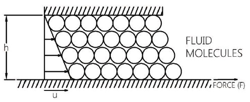 Figure 1. Viscous flow between parallel surfaces
The cohesive forces between the molecules of a fluid create an inherent resistance to flow, which is expressed to terms of its viscosity. Therefore, it requires a force to move the bottom surface relative to the top one. The amount of force required depends on the viscosity of the fluid. The force also depends on the rate at which the fluid molecules are being sheared. The rate of shear for the linear velocity distribution shown in Figure 1 is proportional to the surface velocity u and inversely proportional to the thickness of the film h. Thus, an increase in u or a decrease in h will require a greater force to move the bottom surface. This force is parallel to the surfaces. There is no lifting force which is required for lubrication.
On the other hand, if the surfaces were allowed to collapse, it would take a finite time for the fluid to squeeze out. The momentary lifting force by the fluid, while the surfaces are normally approaching, is called a hydrodynamic squeeze film. The hydrodynamic squeeze film is a useful concept to remember in connection with the mechanism of EHD lubrication.
CLOSING THE GAP
Consider now the flow of fluid between two converging surfaces shown in Figure 2 (a). Here the top surface, which is of finite length, is at an angle to the bottom one. The gap between the surfaces is thicker at the inlet than it is at the outlet. The fluid adjacent to the lower surface moves with a velocity u and the fluid adjacent to the upper surface is stationary. The inlet region would like to drag in fluid uniformly with a velocity distribution that is linear and the outlet region would like to drag out fluid with a linear velocity distribution. The amount of fluid coming in is represented by the area of the triangle in the inlet and the amount of fluid going out is represented by the area of the triangle at the outlet.
Since the triangle in the inlet is bigger, we find that the inlet would like to take more fluid in than the outlet will allow out. This jamming of the fluid into a converging region creates a pressure between the surfaces, as shown in Figure 2(b). The high pressure in the center forces the fluid to slow down in the inlet and makes it go faster at the outlet so that the flow coming in will equal the flow going out.
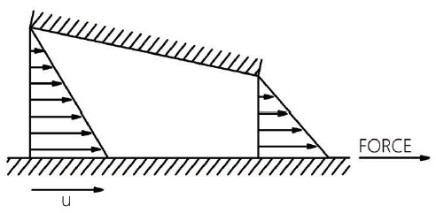 (a) Flow in cannot be larger than flow out.
 (b) Hydrodynamic pressure generation.
Figure 2. Viscous flow between nonparallel surfaces
The pressure that is generated creates a lifting force which separates the surfaces with an oil film. This pressure is a hydrodynamic pressure and the separating of the surfaces due to this pressure is called hydrodynamic lubrication. The load that this bearing can carry depends on the hydrodynamic pressure generated. If the viscosity of the fluid is increased, a greater pressure will be generated, since more work will be needed to slow the fluid down in the inlet. Increasing the velocity u will also increase the pressure, since it will have to slow the fluid down at a faster rate.
There are three basic requirements for the generation of a hydrodynamic pressure of the type shown in Figure 2(b): (1.) the surfaces must be moving, (2.) they must be converging and (3.) a viscous fluid must be between them.
The bearing shown in Figure 2(b) is a simple bearing. It is called a slider bearing or pad bearing. Several of these pads arranged in a circle make a thrust bearing of the type found in many machines.
Another common bearing, which is hydrodynamically lubricated, is the journal bearing shown in Figure 3. Here the converging surfaces are formed by virtue of the fact that the journal is not concentric with the bearing housing. When the journal rotates, it drags fluid into the converging region, thus generating a pressure which separates the surfaces.
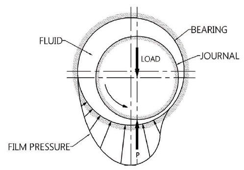 Figure 3. Journal bearing
THE NONCONFORMISTS
Figure 3. Journal bearing
THE NONCONFORMISTS
Hydrodynamic lubrication is characterized by surfaces that are conforming. That is, the surfaces fit onto or into each other quite well so that the load is carried over a relatively large area. There are many machine elements whose contacting surfaces do not conform to each other very well at all. The full burden of the load must then be carried by a very small area of contact. Some examples of these nonconforming surfaces are mating gear teeth, cam and followers and rolling element bearings.
Figure 4 illustrates the nonconforming surfaces of a ball bearing. The ball and raceway conform to some degree in one direction, but the side view of the bearing shows that the curvatures of the ball and race have very little degree of conformity. There was very little belief up until the early 1950s that these nonconforming surfaces with their extremely small area of contact could be separated by an oil film. The lubrication of these nonconforming surfaces leads us to EHD lubrication.
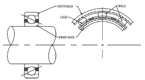 Figure 4. Ball bearing components
HERTZ THE OPPOSITION
Figure 4. Ball bearing components
HERTZ THE OPPOSITION
Let us consider first of all the contact condition between two nonconforming surfaces to see what the mechanism of EHD lubrication is up against. The contacting surfaces of bearings and gears may be represented by a sphere or cylinder loaded against a flat surface, as shown in Figure 5(a). The load, which presses the two bodies together, causes the surfaces to elastically deform and contact each other over a small but finite region of contact. This condition of elastic contact is named after Heinrich Hertz who, in 1881, analyzed the contact between elastic bodies under conditions where the region of contact is very much smaller than the radius of curvature (
2). A close-up view of the intimate region of contact is shown in Figure 5(b). The load gives rise to a pressure called the Hertzian pressure, which is distributed over a small region of contact called the Hertzian region. The pressure has a parabolic distribution, being high in the middle and diminishing to zero at the edges of the contact. Typical maximum Hertzian pressures found in bearing and gear contacts are very high, on the order of 1.4 x 10
9 N/m
2 (200,000 psi). Note that this Hertzian pressure is an elastic pressure due to the elastic deformation of the surfaces.
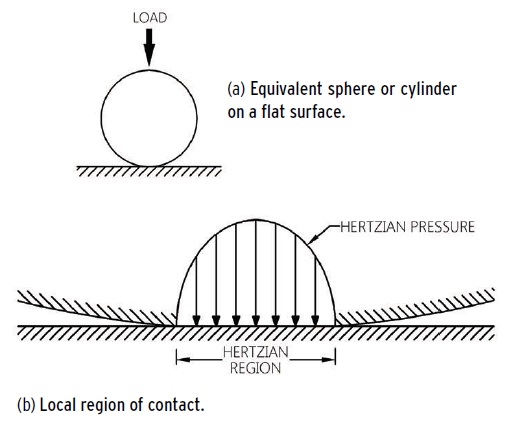 Figure 5. Hertzian condition for dry contact
The Hertzian condition of contact is a dominating feature of EHD lubrication. It establishes the overall shape of the contacting surfaces. Thus, if we were to follow the journey of a fluid particle passing between the surfaces, it would first of all encounter a converging region, followed by a flat region, and finally it would be exposed to a diverging region. As stated before, one of the requirements for the generation of hydrodynamic pressure is that the surfaces must be converging. Therefore, we should expect all of the action to be in the converging region. The hydrodynamic pressure generated in this region has the task of separating the surfaces, which are being forced together by the enormous pressure in the Hertzian region. When we consider that typical maximum Hertzian pressures may be on the order of 1.4 x 10
9 N/m
2 (200,000 psi) and that the usual hydrodynamic pressures generated in journal bearings are on the order of only 7 x 10
6 N/m
2 (1,000 psi) or less, there doesn’t seem to be much hope for the establishment of an oil film under these conditions.
ANKLE-DEEP-IN-CHEESE
The power of elastoydrodynamics is derived from two important considerations, which together provide the teamwork necessary to separate the surfaces. The first is that typical EHD films are very much thinner (about 1,000 times thinner) than they are long. If, for example, the Hertzian region were the length of a football field and you were standing on the field, a typical EHD oil film would only be about ankle deep.
The second important consideration is the effect of pressure on the viscosity of the fluid. Figure 6 shows how the application of pressure influences the viscosity of a synthetic hydrocarbon at 38 C (100 F). The viscosity, which is given in centipose (cp), is plotted on a logarithmic scale because it increases very rapidly with pressure. At atmospheric pressure, the viscosity is about 350 cp (approximately the same consistency as an SAE 30 motor oil). At 0.14 x 10
9 N/m
2 (20,000 psi), the viscosity has increased one order of magnitude to 3,500 cp. The fluid at this pressure has a consistency approaching that of molasses. At typical Hertzian pressures of 1.4 x 10
9 N/m
2 (200,000 psi), the fluid viscosity can increase several orders of magnitude so that its consistency may be more like butter or cheese.
The influence of pressure on viscosity is usually given by a straight line, as shown in Figure 6, which has the equation:
µ = µ
oe
αp [1]
where µ is the viscosity at pressure p and µ
0 is the viscosity at atmospheric pressure. The exponent α is a property of the fluid called the pressure-viscosity coefficient. When α is large, the viscosity rises rapidly with pressure. When α is small, the viscosity rises slowly with pressure.
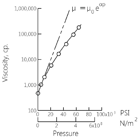 Figure 6. Effect of pressure on viscosity of a synthetic paraffinic oil at 38 C (100 F).
HYDRODYNAMICS VERSUS HERTZ
Figure 6. Effect of pressure on viscosity of a synthetic paraffinic oil at 38 C (100 F).
HYDRODYNAMICS VERSUS HERTZ
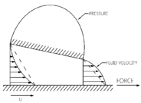
Figure 7 shows the flow of fluid in the convergent inlet region where hydrodynamic pressure is generated. It should be noted that this figure was drawn using two conventions that are frequently employed to graphically illustrate an EHD conjunction region. First, because typical EHD oil films are very much thinner than they are long, the vertical dimensions are usually expanded about 1,000 times greater than the horizontal dimensions. If this were not done, the thickness of a typical EHD oil film, if it were drawn to scale, would be less than the thickness of the horizontal line shown in the Hertzian region of Figure 5(b). The second convention illustrates the contacting surfaces of machine elements with an equivalent sphere or cylinder on a flat surface with all the elastic deformation represented in the curved body.
The shape of the convergent region, as shown in Figure 7, must be viewed with this in mind. The real shape of the convergent inlet region, where hydrodynamic pressure is generated, is actually very long and narrow.
The surfaces shown in Figure 7 are in pure rolling, each moving with the same velocity, u. Each surface carries with it a certain quantity of fluid, which joins together at some location to fill the gap between the surfaces. Fluid adjacent to each surface is attached to it and travels with it. Because the surfaces are converging, the fluid in the interior of the film is forced to slow down and may even flow backwards. Just as we saw before, this slowing down of the fluid generates a hydrodynamic pressure. As the pressure rises in the inlet region, the viscosity also rises with it. The higher viscosity produces even higher pressure. When the fluid reaches the leading edge of the Hertzian region, the viscosity of the fluid may have increased one order of magnitude and the hydrodynamic pressure may have reached typical values of 0.14 x 10
9 N/ m
2 (20,000 psi). This hydrodynamic pressure must compete with the Hertzian pressure. While the hydrodynamic pressure is trying to separate the surfaces, the Hertzian pressure is trying to force them together.
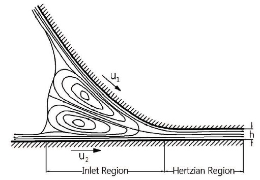 Figure 7. Flow distribution within the convergent inlet region
The hydrodynamic pressure generated in the convergent inlet region is much lower than the maximum Hertzian pressure. Nevertheless, the hydrodynamic pressure is capable of separating the surfaces, and it does so in a very subtle way. It cannot compete with the Hertzian pressure in the center where the pressure is very high, but it can overcome the Hertzian pressure at the leading edge of the Hertzian region where the pressure is much lower. If it does this, and if it separates the surfaces here, then the hydrodynamic pressure will have achieved total surface separation. Total surface separation is achieved because of time. Once the fluid gets into the leading edge of the Hertzian region, it cannot escape because the viscosity becomes too high and the film is too thin. There will not be enough time for the Hertzian pressure to squeeze the fluid out because the motion of the surfaces passes the fluid through the Hertzian region very quickly (typically on the order of milliseconds).
The final pressure that is achieved, as well as the overall shape, are shown in Figure 8. The final pressure and shape are very similar to the Hertzian pressure and shape except at the leading and trailing edges of the Hertzian region. The high local pressure and local constriction at the trailing edge is a result of the requirement to maintain continuity of flow. If there were no constriction, the sudden drop in pressure would force more fluid out than was coming in. Therefore, the surfaces deform in such a manner that they restrict the flow going out.
THE TRINITY
The conjunction zone of a typical EHD contact can be conveniently divided up into three general regions, as shown in Figure 8. Each region performs a particular function. The inlet region pumps the film up. The Hertzian region rides it and the outlet region discharges it. The viscous character of the fluid, while passing through these regions, changes drastically, going from an easy flowing liquid to a pseudosolid and back to an easy flowing liquid within a matter of milliseconds. The viscous properties of the fluid in each region are determined by the temperature, pressure and shear conditions the fluid encounters or creates in each region. It is important to know how these conditions influence the viscous character of the fluid, since viscosity plays an important role in how these regions function.
 Figure 8. Elastohydrodynamic pressure and shape
For example, the film-forming capability of the hydrodynamic pressure generated in the inlet region is governed by the local viscosity throughout this region. Because the inlet region is very narrow, the viscosity is controlled by the temperature of the solid surfaces. The variation of viscosity with pressure is usually accounted for by the α-parameter of Equation[1], which is sufficiently accurate over the pressure range encountered within the inlet region. It is the viscous properties of the fluid, as governed by these pressure and temperature conditions within the inlet region, that influences the thickness of the oil film, which is observed in the Hertzian region.
By the time the fluid has entered the Hertzian region, it has completed its task of pumping the film up. The viscous character of the fluid in the Hertzian region is important, primarily in connection with sliding friction (sometimes called traction). Sliding friction is derived from the Hertzian region because the film is very thin and its viscosity is extremely high. The tremendous enhancement of viscosity with pressure is offset to some degree by frictional heating of the fluid in the Hertzian region, as well as possible shear and time-dependent effects on viscosity. Nevertheless, friction coefficients as high as 0.1 can still be achieved under certain conditions.
After the fluid leaves the Hertzian region, it enters a diverging region which attempts to generate negative pressures. When small subambient pressures are reached, the gases, which are dissolved in the fluid, come out of solution and fill the space between the surfaces in the outlet region. This film cavitation or “passing gas” terminates the pressure profile.
PREDICTING FILM THICKNESS
The practical importance of the mechanism of EHD lubrication lies in the thickness of the oil film between the surfaces. Its thickness is controlled by the operating conditions expressed in terms of various operating parameters such as surface velocity, load and fluid viscosity.
The influence of these parameters on film thickness should be obvious if the basic concepts of elastohydrodynamics have been understood. For example, a change in any parameter, which causes a greater hydrodynamic pressure to be generated in the inlet region, will result in a larger film thickness. Thus, an increase in surface velocity or fluid viscosity will result in a larger film thickness.
An important feature of EHD lubrication is that the influence of load on film thickness is very small. This is not surprising if one considers that an increase in load merely increases the maximum Hertzian pressure and makes the Hertzian region larger. It does very little to the inlet region where the hydrodynamic pressure is generated.
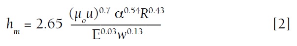
The influence of various operating parameters on film thickness can be shown with an equation. One of the early equations (
see Equation [2]) has been derived from theory (
3) for a line contact geometry represented by a cylinder on a plane, as shown in Figure 5 (a).
Where
hm = film thickness at the rear constriction
μ
0 = viscosity at atmospheric pressure
α = pressure-viscosity coefficient as defined in Equation [1]
u = velocity defined as
u = ½ (u1 + u2) where
u1 and
u2 are the individual velocities of the moving surfaces
R = radius of equivalent cylinder
w = load per unit width
E = elastic modulus of equivalent cylinder (flat surface assumed completely rigid)
The above equation shows that film thickness is most sensitive to the velocity (
u), the lubricant properties (µ
o and α) and the radius of curvature (R). An increase in any one of these parameters, which are the numerator of Equation [2], will result in a larger film thickness. The denominator has two parameters (E and w) which tend to decrease film thickness. However, neither the load w nor the elastic modulus E influence film thickness very much since their exponents are very small (0.13 and 0.03). It is somewhat ironic that the type of lubrication which bears the name elastohydrodynamic shows very little dependence on the elasticity of the materials. As long as the elastic deformation is similar to the Hertzian deformation, it doesn’t matter if the elastic modulus is high like that of tungsten carbide or low like that of aluminum or glass.
If the elastic modulus is extremely low, like that of rubber, the pressure will not be sufficient to enhance the viscosity of the fluid. The mechanism of lubrication, while still elastohydrodynamic, cannot be described by Equation [2] since it includes the pressure-viscosity coefficient α.
For moderately hard materials, the theoretical prediction of film thickness, as represented by Equation [2], has been verified by experimental measurements. These measurements are difficult to make because typical EHD films are extremely thin (on the order of 0.5 x 10
-6 m or 20 x 10
-6 in).
One measurement technique that has been used is optical interferometry, which uses the wavelength of light as a unit of measure. Figure 9 shows a photomicrograph of the light interference fringes, which have formed between a steel ball rolling against a glass surface. The circular area is the Hertzian region. The fluid passes through the Hertzian region from left to right with its cavitation clearly visible in the outlet region. The interference colors in the Hertzian region provide a contour map of the thickness of the oil film. The green color in the center indicates that the film is very parallel except for the constrictions at the rear and sides of the Hertzian region. The side constrictions are the result of side leakage of the fluid immediately upstream in the inlet region. This side leakage inhibits the generation of hydrodynamic pressure, which results in a smaller film thickness.
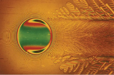 Figure 9. Photomicrograph of optical interference fringes formed between a steel ball and glass surface.
TICKLE OR SCRATCH
Figure 9. Photomicrograph of optical interference fringes formed between a steel ball and glass surface.
TICKLE OR SCRATCH
The thickness of EHD lubricating films found in bearings and gears is frequently not much larger than the height of individual asperity roughness on the surfaces. If total surface separation can be achieved, the life of bearing and gear components can be expected to be very long, being limited ultimately by fatigue of the metal surfaces. However, when total separation of the surfaces is not achieved, the load is supported partially by the EHD film and partially by local areas of asperity contact. These local areas of contact are vulnerable sites for the initiation of surface wear and failure. The thickness of the EHD film relative to the individual asperity heights is an important design criteria. It will determine whether the intermittent contact between asperities is just tickle or a scratch.
SUMMARY
We can say that EHD lubrication deals with surfaces that are elastically deformed by loads, which must be carried over small areas. The overall pressures and deformations are similar to the Hertzian conditions for dry contact. Surface separation is achieved by hydrodynamic forces because viscosity increases with pressure, which enables relatively high hydrodynamic pressures to be generated.
Although these pressures may be much smaller than the maximum Hertzian pressure, they are still sufficient to separate the surfaces at the leading edge of the Hertzian region. Once this is achieved, the fluid finds that it cannot escape because its viscosity is too high, the gap between the surfaces in the Hertzian region is too thin and the time is too short.
REFERENCES
1.
Reynolds, O., “On the Theory of Lubrication and its Application to Mr. Beauchamp Tower’s Experiments Including an Experimental Determination of the Viscosity of Olive Oil,”
Phil. Trans., (1886),
177, (i), pp. 157-234.
2.
Hertz, Heinrich, R.,
Reine Angew. Math. (Crelle’s j.),
92, 1881, pp. 156-171.
3.
Dowson, D., “Elastohydrodynamics,”
Proc. Inst. Mech. Engrs.,
182, Part 3A, 1967-68, pp. 151-167.
 Vern Wedeven is an STLE Fellow and the founder of Wedeven Associates, Inc., in Edgmont, Pa. You can reach him at vwedeven@wedeven.com
.