What’s a gear?
Dr. Robert M. Gresham, Contributing Editor | TLT Lubrication Fundamentals July 2012
An overview of the machine elements that keep the industrial world turning.
KEY CONCEPTS
•
Gears are machine elements that transmit motion by means of successively engaging teeth.
•
Gears are classified according to the relative position of the axis of their revolution.
•
Gears are made from a variety of materials depending on cost and application.
HOW MANY OF YOU ARE OLD ENOUGH TO REMEMBER WALT DISNEY’S GYRO GEARLOOSE? Probably not many. I suppose he was the first fictional tribologist. In fact, old Gyro was around before the word tribologist was coined. Gyro, who first appeared in Walt Disney Comic Book No. 140 in 1952, was a brilliant inventor of all kinds of humorous gadgets and devices, many of which included quite novel gear sets.

One can’t help but wonder how much he knew about the lubrication of his somewhat uniquely geared inventions. So let’s take a brief look at the world of gears.
First a definition: Gears are machine elements that transmit motion by means of successively engaging teeth. The gear teeth act as small levers. In general, gears are classified according to the relative position of the axis of their revolution. Thus, these axes are parallel, intersecting or, as you might guess, neither intersecting nor parallel—but non-intersecting.
Thus, gears connect shafts that operate from these different directions and, depending on the relative diameters and/or numbers of teeth per gear, can multiply speed or force in a manner analogous to a lever. So gears can reduce or increase speed, transmit power, increase or decrease torque, change direction and change axis of direction. Pretty handy traits for design engineers. Some of the more common gear types are:
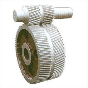
SPUR GEARS
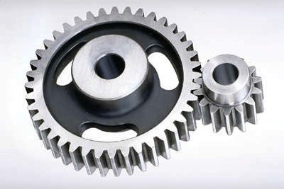 External Spur Gears
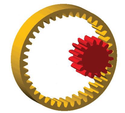 Internal Spur Gear
Spur gears or straight-cut gears are the simplest type of gear. Spur gears connect parallel shafts and have involute (curling inward) teeth, parallel to the shafts (
see diagram).
Spur gears consist of a cylinder or disk with the teeth projecting radially and, although not straight-sided in form, the edge of each tooth is straight and aligned parallel to the axis of rotation. These gears can be meshed together correctly only if they are fitted to parallel shafts. Spur gears are relatively inexpensive to manufacture, cause no axial thrust between the gears and, while giving lower performance than other gear types, are generally satisfactory in low-speed, simple applications. They can be noisy at higher speeds.
 Involute Tooth
HELICAL GEARS
Involute Tooth
HELICAL GEARS
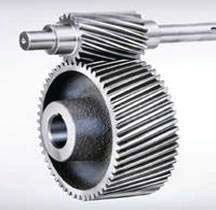 Parallel Helical Gears
 Crossed Helical Gears
Helical gears offer a refinement over spur gears. Helical gears can be meshed in parallel or crossed orientations. Helical gears also have involute teeth and are cut at an angle (called the helix angle) to the axis of rotation. Since the gear is curved, this angling causes the tooth shape to be a segment of a helix. The mating gears must have the same angle but in opposite hands (left and right). The angled teeth engage more gradually than do spur gear teeth, causing them to run more smoothly and quietly because there is continuous tooth contact. A disadvantage of helical gears is a resultant thrust along the axis of the gear, which needs to be accommodated by appropriate thrust bearings. The greater degree of sliding friction between the meshing teeth is often addressed with antiscuff and antiwear additives in the lubricant.
Helical gears are found in high-speed applications where good performance is needed. As you might expect, they can carry higher loads as there is a greater tooth cross section. Obviously, they are more expensive to manufacture. Another way to combat the axial thrust property is to use herringbone gears.
HERRINGBONE GEARS
Herringbone gears consist of two helical gears of opposite hands that are mounted side- by-side on the shaft and thus cancel the resulting thrust forces.
 Herringbone Gears
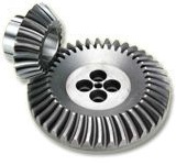
INTERSECTING SHAFT GEARS
Herringbone Gears
INTERSECTING SHAFT GEARS
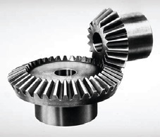 Bevel Gears
 Zerol Gears
 Spiral Bevel Gears
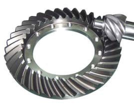
Hypoid Gears
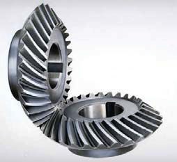
BEVEL GEARS
Spiral Bevel Gears
Hypoid Gears
BEVEL GEARS
Bevel gears have a conical configuration as opposed to cylindrical for spur and helical. Thus, the two gears are, in effect, two truncated cones in rolling contact. Within this configuration there are straight bevels, which are like spur gears with no helix angle. Examples of bevel gears are miter gears, equal in size with a 90-degree shaft angle, angular gears with shaft angles other than 90 degrees, and crown gears where one gear is flat with a pitch angle of 90 degrees. Zerol bevel gears are an intermediate type between straight and spiral bevel gears. Their teeth are curved or crowned, so that contact takes place at the tooth center not angled. Spiral bevel gears are analogous to helical gears but with a conical configuration. A hypoid gear is an example of a bevel gear that is neither parallel nor intersecting. Other examples of non-parallel and non-intersecting shaft gears are crossed helical gears and worm gears.
Crossed helical gears are used where the shafts are not parallel and not intersecting but rather skewed. They can be at 90 degrees or other angles. The teeth necessarily slide more and are, therefore, less efficient and often require highly additized lubricants.
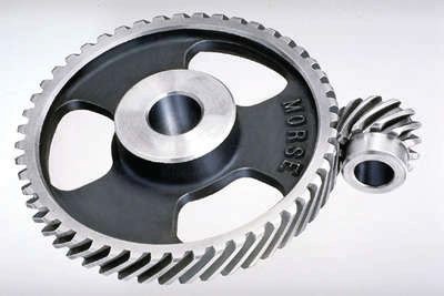
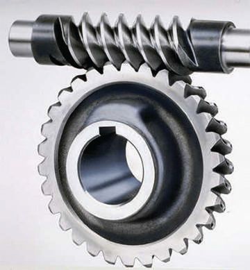
Worm gears are used when large gear reductions are needed. It is common for worm gears to have reductions of 20:1 and even up to 300:1 or greater. Many worm gears have an interesting property that no other gear set has: the worm can easily turn the gear, but the gear cannot turn the worm. This is because the angle on the worm is so shallow that when the gear tries to spin it, the friction between the gear and the worm holds the worm in place. This feature is useful for machines such as conveyor system in which the locking feature can act as a break for the conveyor when the motor is not turning.
 Crossed Helical Gears
 Worm Gears
ROTARY TO TRANSLATION GEARS
Worm Gears
ROTARY TO TRANSLATION GEARS
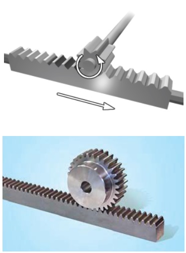 Rack and pinion (The rack is like a gear whose axis is infinity)
These gears transmit rotary motion from pinion to translation motion of the rack. The rack amounts to a gear of infinite radius with flat involute teeth.
The different designs of gears of gears is an extremely complex subject and beyond the scope of this article. Figure 1 depicts a diagram of a gear that shows the key element of gear design.
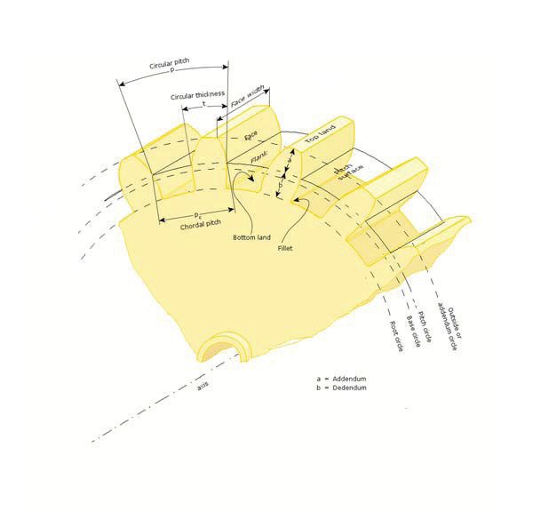 Figure 1. Key Elements of Gear Design
Gear are made from a variety of materials dependent upon cost and the application. These materials include cast iron, powdered metals, steel, a variety of special nonferrous alloys and non-metallics such as the group of engineering plastics: nylon, acetal, UHMWPE, etc.
Gears are used in a wide variety of combinations in a wide variety of applications, such as in clocks, copiers, huge bull gears in drag lines, drawbridges, industrial gearboxes and related industrial equipment and, of course, truck and automobile transmissions and differentials. In future articles, we will explore some of the challenges in gear lubrication.
 Bob Gresham is STLE’s director of professional development. You can reach him at rgresham@stle.org
.