Ultrasonic energy measurement to improve effective lubrication practices
Mike Johnson & John W. Ward, Jr. | TLT Best Practices June 2012
Consider these data-collection methods to develop a well-defined relubrication program.
KEY CONCEPTS
•
When objective numerical values supplant subjective decisions, machine lubrication effectiveness improves.
•
Data collection requires exacting repeatability, regardless of collection methodology, to avoid misdirection from poor data.
•
Signal interpretation is complicated by such factors as machine speeds, loads and bearing sizes.
Grease-based lubrication practices occupy a large amount of the available time dedicated to machine lubrication activities. In previous TLT articles, we have addressed a process one could follow to optimize these practices to a significant extent. For some production sites where grease lubrication practices were established years ago and without an objective quantitative basis, such as the DIN 51825 standard, that can mean returning man-hours to the labor pool to pursue additional meaningful activities (
Note: More information on this topic can be found in the April 2009 TLT, available digitally at www.stle.org).
Though quantitative means are an appropriate starting point, there are plenty of applications where fine-tuning is needed. As a rule, the higher the speed, the greater value can be derived from actually measuring the effectiveness of the lubricant film before additional grease is applied.
If the lubricant film is intact, adding additional lubricant is a waste of time and materials. If the lubricant film has been depleted and the bearing is running in a boundary state, the bearing should be replenished.
There are instruments available to help the reliability engineer and lubrication technician measure the presence of boundary state conditions, regardless of the calculated baseline. The degree of objectivity (results based strictly on the numbers) differs between the available instruments. Whenever objective (numerical) values can be used to supplant decisions previously made on subjective terms, machine lubrication effectiveness improves.
This article introduces the concept of condition-based lubrication practices using high-frequency energy measurement techniques, which was discussed in the
February TLT (also available digitally at
www.stle.org).
ROLLING MACHINE CONTACTS
Previously, we introduced the idea of extremely high-frequency energy being produced by operating machines. This specific type of energy form is referred to as compression wave energy and ultrasonic energy. Although it is difficult to capture without well-defined data-collection techniques, this energy can be systematically captured and measured. A comparison of energy states between measurements gives reliability technicians a means to characterize oil film thickness effectiveness.
For any rolling contact (bearing, gear pitchline), the protective oil film is trapped between two surfaces, creating a separating barrier. As long as the flow of oil (from either an oil sump or a body of grease surrounding the component) is maintained, the separating film is intact. Furthermore, as long as the product was properly selected to produce the optimum viscosity at machine operating temperature, the surfaces will float on an uninterrupted film of oil. The purple area in the bearing diagram shown in Figure 1 represents the contact point where this oil film is maintained.
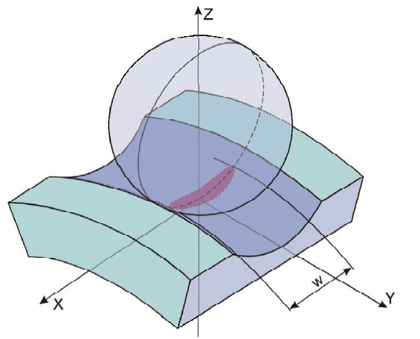 Figure 1. The area of surface deformation under normal load is shown in purple. (Courtesy of Lubcon GmBH)
When the oil film is ruptured and surface asperities from one surface contact asperities of the mating surface, the impacts create an energy wave. The wave travels well through solid surfaces and is transmitted directionally through the component body. When multiple asperities collide, such as when the oil film has dissipated from the loaded surface, the amount of energy produced rises dramatically. Figure 2 shows this energy as it’s produced at its point of origin.
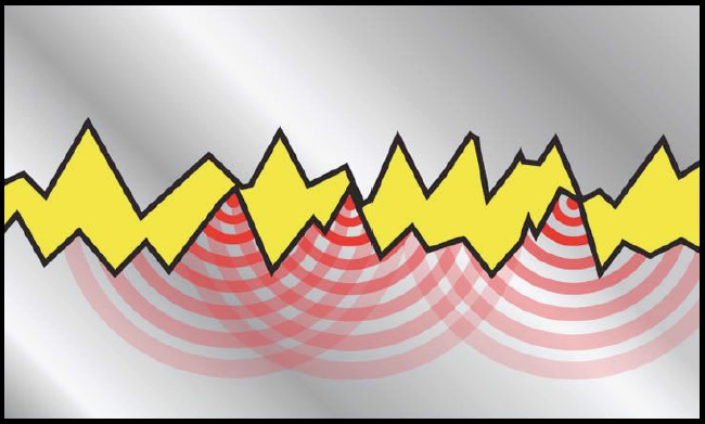 Figure 2. Represents what is likely any time the oil film is lost, and the number of asperity contact events increases. (Courtesy of SPM Instruments)
Since ultrasound is produced with normal elastohydrodynamic film formation, it is reasonable to expect new and properly lubricated (oil or grease) bearings will produce some ultrasound. As the shaft rotational speed increases, the incidence of asperity contact at the element and race surface also increases, and the ultrasonic energy intensity increases. The energy is typically reported in decibels (dBs).
CONDITION-BASED GREASING
The reliability engineer must determine how much of the ultrasonic energy is normal and how much is from a deteriorated lubricant film condition for each bearing to be tracked and for a given operating state. This should be done empirically before one asserts that the bearing’s recorded dBs reflects an appropriate (correct) operating state.
Variables that may negatively affect readings include:
•
Bearing type
•
Bearing size
•
Shaft speed
•
The volume of fresh lubricant in the bearing
•
The volume of residual lubricant in the housing
•
Lubricating oil viscosity
•
Bearing dynamic load
•
Overall mass of the bearing mount
•
Mechanical boundary layers the signal must penetrate
•
Metallurgical differences at boundary layers
•
The angle of measurement
•
Sensor placement (too close or too far away from the point of emanation).
In order to avoid influences from these conditions, the data-collection process should be very well-defined and observed. Data collection must occur with exacting repeatability, regardless of collection methodology, to avoid misdirection from poor data. Instrument suppliers propose generically that ultrasound information should be collected on a bearing during optimum operating condition to establish a baseline reading. This is good advice.
Consider the following steps for ultrasonic energy data collection and evaluation needed for relubrication:
1.
Calculate the proper viscosity requirement at the machine’s operating temperature and select the appropriate product. The proper frequency and volume for grease is also calculated if it is a grease-lubricated application. Organize replenishment activities according to the calculated values into a linear sequence.
2.
Schedule and complete the grease sequence (route). Record bearing temperatures within a few minutes following routine replenishment.
3.
Document the instrument make/model number and the sensor make/serial-model number for the bearings that are to be evaluated. Assume that sensors and instruments are not interchangeable. Readings should always be taken with the same sensor and instrument each time to maintain trendability for a route.
4.
On the initial cycle, find the place on the bearing that produces the best quality signal. This can be done by attaching a stinger probe to the instrument and searching for the high-energy location on the housing. It should be at the front or back face of the bearing in the third of the circumference that represents the load zone. For overhung loads, it will be in the direction toward the driven component. Data collection can occur perpendicular to the shaft axis in the region of the load zone. Mark the data collection spot for future measurement. If it is not possible to determine or to reach the load zone, select a clean, flat, preferably unpainted surface as the designated collection point. Vibration collection points may or may not be useful given their location and possible sources of error (metallurgy, mechanical interferences, etc.).
5.
Within one hour of relubrication, start the data-collection routine. Check and compare the operating temperature with the temperature recorded at the time of lubrication. If a rise of more than 10% occurred, it is likely that churning is present and the ultrasonic energy reading may produce misleading data. Once the temperature is stabilized, record the energy value and assign it as the default decibel value.
6.
Record any deviation from the normal operating state (speed, process rate or load variation). This is the baseline reading. If the component was outside of the default operating state, this reading should be repeated when the default operating conditions can be replicated.
7.
For those machines that operate with normal variability in speed or load, the established default state at initial data collection has to be repeated for each future collection. Even if the conditions are the worst possible case, they should be duplicated once they are set. Any time a change in the default operating states occurs, the trending must be restarted. This may seem overly detailed, but it is necessary to minimize variability in high-frequency energy production.
8.
Prior to the next lubrication interval, use the selected instrument and sensor to measure and record the current state. Assuming the new reading is an accurate measurement, a change of 6± decibels represents a 100% increase in signal intensity, indicating that the lubricating film is partially or fully lost.
9.
If the decibel reading drops, verify that the reading was taken in precisely the same way as the last time through. Make sure the speed and load conditions are the same or very similar. If all checks out, replenish with the predefined amount of the selected lubricant according to the plan. If the operating state does not meet the baseline, replenish (
see Step 10) and reschedule the measurement to be completed (soon) when all the prerequisites can be met.
10.
With the sensor on and running, add grease with slow single strokes of the gun to gradually reintroduce fresh lubricant. If a grease volume meter is used, introduce half-gram increments each few seconds. Add grease until a decibel level increase is observed. Record the amount introduced, the temperature and the decibel reading for future use and adjust (extend) the normal replenishment interval by one-fourth.
11.
If the decibel reading increases, replenish the lubricant (
see Step 12).
12.
With the sensor on and running, add grease with half-strokes of the gun to gradually reintroduce fresh lubricant. If a grease volume meter is used, introduce half-gram increments each few seconds. A decibel decrease should be observed after a film is reintroduced to the surfaces. Repeat the steps as long as the decibel level continues to decrease. When the decibel value ceases to decrease, pause for 30 seconds. If the decibel value increases, repeat the steps again. When the decibel value hangs for more than a minute, stop lubricating the bearing.
13.
Note the replacement volume and adjust (shorten) the schedule by one-fourth of the current period. Adjust the required volume to match the amount that was just introduced. These values become the new frequency and volume baseline. Repeat the reading practice at the adjusted intervals until there is stability through three complete unadjusted cycles.
14.
After the correct frequency and volume has been fully determined, it is appropriate to periodically spot check the routes to verify continued effectiveness.
15.
If a change in lubricant type, grade, operating conditions (load, speed, heat load, moisture or solid contamination state) or sensor and instrumentation occurs, the entire data point should be reinitiated.
Coupling other sensory methods with ultrasonic measurements improves the efficiency and likelihood for rendering a successful judgment call.
QUALITY AND DEPENDABILITY
There are still many questions about the repeatability and dependability of this type of approach. As is the case with all measurement techniques, the sample collection practice can have a significant impact on data usefulness. As sensor proximity to the point of emanation improves, the quality and dependability of the technique improves.
Signal intensity declines as the sensor placement is moved away from the point of signal generation and across mechanical interfaces. Where interface metals are dissimilar, signal loss increases. Equipment owners can overcome data-collection issues with the use of remotely-mounted sensors and stud-mounted locking sensors. Unfortunately, close proximity is a challenge. Metallic or plastic guards and covers often obstruct the load zone for shaft bearings. These require modification to gain proximity, which requires planning, approval of work orders and time during outages.
Further complicating matters are differences between machine speeds, loads, bearing sizes and capacity to manage overloading and the normal surface compression that occurs with EHD film formation, which all complicate signal interpretation. There is no clear parallel between ultrasonic analysis for lubricant film effectiveness measurement and pattern recognition from routine vibration-based monitoring (imbalance, misalignment, shaft straightness, looseness, etc.).
Instrument vendors have aggressively promoted the fundamental technology as being simplistic enough that cursory observation of audible and visual indicators is adequate to achieve precise adjustments in lubrication. Technicians can clearly see and hear something, but without recognizing the layers of variables it is possible to either fail to recognize or mistakenly insert meaning into the readings. In the absence of clearly defined patterns, the discrepancies are difficult to identify. The mechanism to overcome uncertainty is to fully vet data collection to deliver the component’s maximum signal intensity to the data logger/collector.
The bearing manufacturing community has not yet provided documentation that defines the single best practice that may be broadly applied to element-bearing lubricant film measurement. Documentation is expected to occur following adequate collection and analysis of data.
SUMMARY
Ultrasonic energy measurement can be a highly useful tool to optimize bearing lubrication volumes and intervals. It is vitally important to have repeatable data-collection methods defined that include collection of the data from the correct physical location on the bearing or machine component.
Physical modification to existing guards may be needed to assure correct results. There is no clear and simple corollary between frequency and pattern recognition from broad-based vibration analysis practices and ultrasonic energy programs, but with a well-defined program and a proper data-collection technique in place, a step-by-step routine can be followed that provides the lubrication technician with a best possible replenishment routine.
 Mike Johnson, CLS, CMRP, MLT II, MLA III, is the principal consultant for Advanced Machine Reliability Resources, in Franklin, Tenn. You can reach him at mike.johnson@precisionlubrication.com
.
 John Ward, Jr., MLT II, MLA II, is a senior reliability engineer with AMMRI. You can reach him at john.ward@precisionlubrication.com
.