Integrating online sensors and filtration for moisture management
Mike Johnson, Contributing Editor | TLT Best Practices October 2011
Newer methods are providing better results than traditional sampling, processing and reporting techniques.

www.canstockphoto.com
KEY CONCEPTS
•
Common methods for measuring moisture loads require collection of a lubricant sample to report a value.
•
Several options for continuous monitoring measure water concentration as a percentage of fluid saturation at a given temperature.
•
Regardless of the unit, a machine has the potential to schedule its own fluid conditioning activities.
Several well-respected authors have discussed the challenges of machine health and plant productivity posed by moisture contamination of lubricating oils. The charts provided by bearing manufacturers showing the decline in L
10 lifecycles versus water concentration are compelling. Outside of the hard data, any mechanic worth his/her weight in salt knows to inspect the sight gauge for evidence of the haze that tells of moisture saturation and contamination.
It seems safe to say that maintenance and reliability practitioners agree on a central point: water contamination is a problem for machine health. As shown in Figure 1, even low concentrations of moisture can have a meaningful negative impact on machine components such as bearings (
1). Coincidentally, the value of monitoring and remediating moisture in key production machines is accepted.
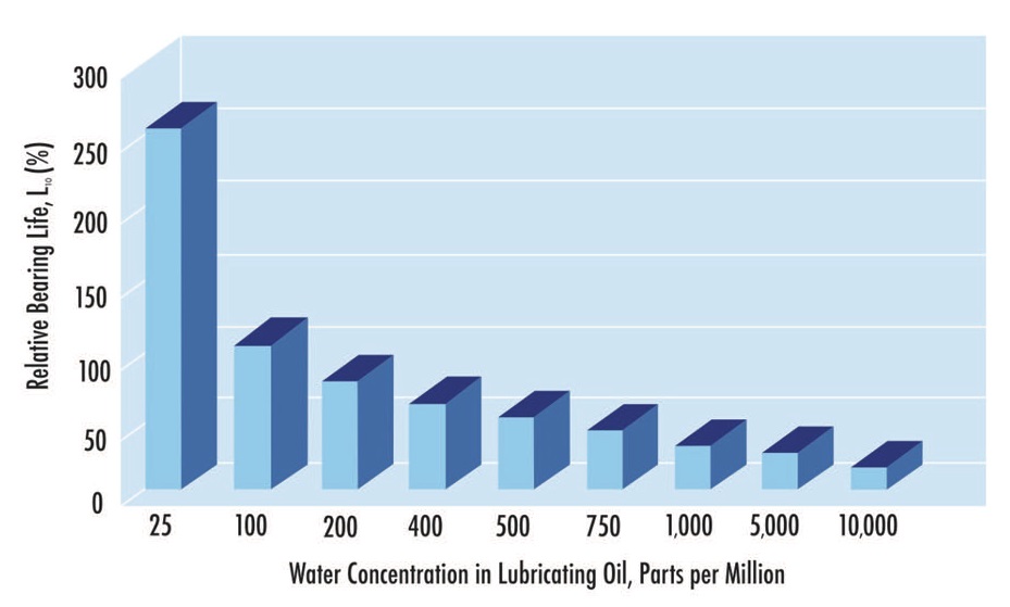 Figure 1. Expected bearing L10 impact for several moisture levels.
Even so, water measurement and removal is a somewhat haphazard pursuit that is dependent on sample collection, processing, reporting and then scheduling a response. Though this has been the steady approach in the modern manufacturing age, there is a better way.
In this article, we will briefly review water measurement and investigate the idea of integrating continuous measurement with condition-based operation of moisture-removal systems.
MOISTURE ANALYSIS METHODS
There are several common tests used to measure and report moisture in parts per million (ppm), including non-quantitative methods, as shown in Figure 2.
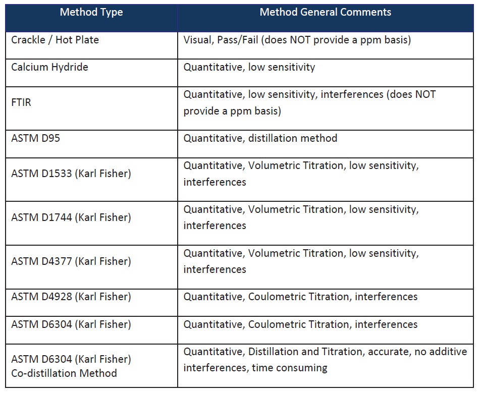 Figure 2. Commonly accepted methods for moisture measurement in lubricating oils.
While each of these has its strengths, the 6304 method with codistillation is the most dependable for additive-enhanced lubricating oils. This method distills moisture and then titrates the condensate in a solvent to determine an accurate representation of total moisture in the oil sample. This method can reportedly provide results into single-digits ppm.
Each of these methods also requires the use of sample collection and handling, either inside the plant or sample shipment to a lab for processing. The lab-based methods (all but the first two) add processing time to the total interval. Collectively, these factors are time-consuming and can represent a strong drawback to moisture analysis.
Additionally, except for the hotplate approach (which is essentially a pass/fail test), the value produced is displayed as a value in ppm. This unit of measure has become the default unit of presented results. It is aligned with wear metals reporting, and is intuitive and, therefore, is accepted uniformly without question as the right approach. It is neither right nor wrong.
CONTINUOUS MEASUREMENT
Within the last few years, several companies have produced continuous monitors designed to measure water as a percentage of water saturation in the fluid for a given temperature. This approach produces a unit of percent water saturation in the oil. While that may not seem like a tangible unit to report, if the contamination control objectives are defined by percent saturation, it will produce useful corrective actions.
Saturation and relative humidity are similar values along the same contamination control line. A fluid that registers 100% relative humidity is saturated. It cannot hold any more water at the test temperature. At this point, water will aggregate into bubbles that may fall or be suspended in the oil, producing the tell-tale cloud that we have traditionally looked for. Conversely, a lubricant that registers zero percent relative humidity is completely dry.
The amount of saturation changes with temperature, much the same way the amount of moisture in the air changes with temperature. If the sump temperature drops, it may cross the saturation point and effectively drop water from a dissolved to a free or emulsified state. This is somewhat like the temperature dropping during the night below the dew point and creating condensation moisture on stationary surfaces. The dew point of the water in the lubricant is dependent on additive type and concentration and base oil type.
A quick Google search produces several moisture sensor brands from which to choose. There are many similarities and a few differences in how they are intended to be used. Some of those brand names are included in Figure 3.
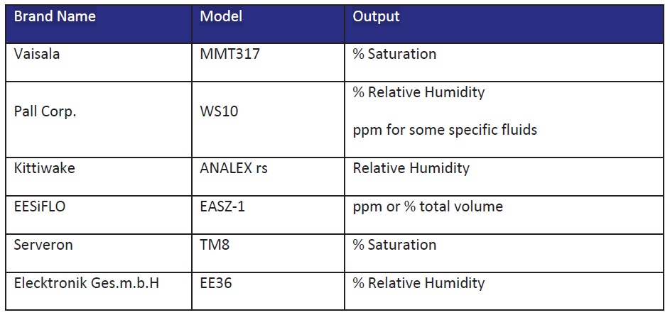 Figure 3. Continuous moisture measurement sensors.
ALARM LEVELS
Figure 3. Continuous moisture measurement sensors.
ALARM LEVELS
Moisture alarm limits for lubricating oils are customarily set in ppm, but using a sensor measuring in percent humidity requires that the level be set accordingly. Controlling moisture at or below 50% saturation levels would provide appropriate protection for both machine parts and lubricating oil. The amount of moisture that represents 50% is also a function of temperature and product type.
To avoid free water formation, it would be appropriate to set the control limit at the lowest likely temperature that the machine would routinely achieve. This is most likely to occur in association with outages. If the plant ambient temperature and, therefore, system temperature can fall to 80 degrees during a summer outage and 50 degrees during a winter outage, then the set point would be 50% at 50 degrees F, as shown in Figure 4.
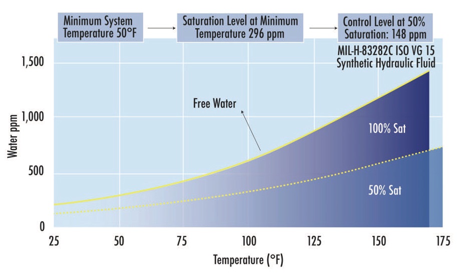 Figure 4. Saturation level at two temperatures for a mil-spec hydraulic oil.
Aside from providing a safeguard for likely condensation during outages, a low set point like this assures that attention is provided at a moisture level low enough that long-term reliability is achieved.
SUMP CONDITION CONTROL
The challenge of driving moisture out of the system begins after the target alarm levels have been established. There are several manufacturers of dehydration systems that produce filters capable of circulating and dehydrating at either low or high flow levels, depending on sump capacity.
Vacuum Dehydration. Vacuum dehydration is a preferred method for moisture removal because it allows for rapid water evaporation at relatively low temperatures. This technique incorporates the use of a vacuum chamber creating a low-pressure condition at approximately 25 inches of mercury (vacuum). At this low pressure, water boils at a temperature of 134 F/57 C. Accordingly, the temperature of the oil in the vacuum chamber is raised to +/- 150 F and the water evaporates quickly. Low thermal stress is applied to the lubricant, and the water is decanted.
Vacuum dehydrators may incorporate oil sprays or thin film exposure by draining the lubricant across a metal surface to facilitate more rapid removal than would be possible with only movement through the sump. While not necessarily the point of this article, it should be noted that air, solvents and other high-volatility contaminants can also be removed with vacuum dehydrators, making this technology a key factor in condition control for large sumps and critical machines.
Vacuum dehydrators are relatively complex and require careful attention to the operation and routine care of the whole system. Many vacuum dehydrators have been abandoned because the production site didn’t have the knowledge or motivation to keep the systems in effective operating order.
Air Stripping. Dehydration by air stripping, Figure 5 provides a competitive alternative to vacuum-based means. This type of system is also capable of removing free and emulsified moisture and can remove most dissolved moisture approaching double-digit levels.
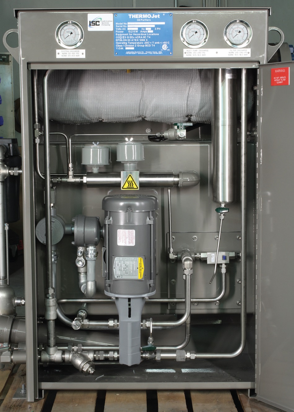
Figure 5. The Thermo-Jet Air Stripper by LSC has only one moving component: a pump.
One could think of the function of an air-stripping dehydrator as working along the same lines as an oversized hair dryer dehydrating a stream of oil. Air stripping works by diffusing heated oil into an air chamber—using warm air to draw moisture out of the hot lubricant. The lubricant is then coalesced and returned to the lube-oil tank, and the moisture is coalesced and decanted.
Air strippers do not have vacuum pumps or vacuum chambers to maintain. Coincidentally, these are simpler and cost less to maintain than a typical vacuum dehydrator. The fact that it can also remove other gaseous impurities, as well as dissolved water, makes air-stripping technology an effective alternative to vacuum dehydration.
Several other methods exist that can assist in water removal. These two technologies are of interest for the opportunity to integrate auto-conditioning triggered by actual condition assessment. This could be considered a possibility for any permanently mounted contaminant control system.
SUMP DEHYDRATION
When the means to conduct continuous assessment exists and the assessment tool has an output that can be integrated into a process controller at the plant site, there is potential to have the machine schedule its own fluid conditioning activities.
Any condition-assessment sensor with a programmable alarm setting and an output can be used to control the operation of the dehydrator. As the sensor detects a moisture load above the set maximum, the sensor controller can send a signal to a controller to cycle on the dehydration system. If the system can operate without direct human intervention, then the condition control loop is self-determined.
As long as there is enough removal capacity to remove water ahead of its relative rate of ingression, and as long as the removal system can function without increasing risk-of-failure due to malfunction (such as a hose busting and pumping all of the oil out of the tank), the lubrication technician can get busy with the work of improvements and maintenance on other machines. The operational questions should be answered during the sizing and engineering of the closed loop system.
CONCLUSION
Relatively low levels of moisture contribute measurably to the demise of the lubricant and the machine’s components. New sensors let the reliability practitioner continuously assess the amount of moisture present in a system. The preference unit of measure is relative humidity or fluid saturation. Saturation differs by fluid and temperature. Additionally, saturation alarm levels should be set at 50% of the likely level when the sump reaches its coldest temperatures.
Once accomplished, this control loop may be attached to one of the available removal systems through a programmable controller to cycle on whenever the lubricant exceeds the alarm point. The variables that may limit the effectiveness of this type of closed loop control system can and should be engineered out during system sizing and configuration.
REFERENCES
1.
Cantley, R.E. (1977), “The Effect of Water in Lubricating Oil on Bearing Fatigue Life,”
ASLE Transactions,
20 (3), pp. 244-248.
 Mike Johnson, CLS, CMRP, MLT II, MLA III, is the principal consultant for Advanced Machine Reliability Resources, in Franklin, Tenn. You can reach him at mike.johnson@precisionlubrication.com
.