Nanotechnology: Science meets machine reliability
Mike Johnson, Contributing Editor | TLT Best Practices September 2011
Our ability to measure surface asperities with far greater precision is extending component lifecycles.
KEY CONCEPTS
•
Measurable surface damage often occurs from abrasive and adhesive contact.
•
Several lubricant companies have developed additives used in finished lubricants to halt damage and improve machine surfaces.
•
A silicate-based agent is produced when chemi-physical reactions work to induce a ceramic-like protective machine surface.
Even though he didn't know it in September 1966, James T. Kirk, the Trek,” introduced the futuristic concept of applied nanotechnology to the unsuspecting masses in the form of the food replicator. However, 45 years later the notion of nanomanufacturing has scientists wondering how nanotechnology in its mature manifestation may help to cure cancer, eliminate food and water shortages and change the nature of how we make things.
What does this have to do with tribology? As it turns out, nanotechnology offers great promise for tribology through the science and art of corrosion and friction control. This article features case studies about using metal treatment to reduce surface roughness and friction and extend component lifecycles after the machine has been placed into operation.
NANOTECHNOLOGY
While we're not accustomed to thinking about them. microscale dimensions are central to decisions involving filtration and contamination control. To put things in a metric frame of reference, a centimeter is a hundredth of a meter, a millimeter is a thousandth of a meter and a micrometer is a millionth of a meter. A nanometer is a billionth of a meter, smaller than the wavelength of visible light and a hundred-thousandth the width of a human hair (
1).
Lubricating oil films for element bearings and other rolling contacts can range from a half to one and a half microns thick or approximately a sixth to half the width of a red blood cell. Sliding-surface oil films (hydrodynamic films) are much fatter at three microns and larger, depending on the machine’s speed, load, surface area and oil viscosity. One must think deliberately to imagine these dimensions relative to the size of the apparent contact areas for common components.
LUBRICATING FILMS AND SURFACE PROTECTION
Lubricating films aren’t any thicker than the combined height of each of the two machines’s working surfaces. There are, of course, differences in the machine’s combined surface roughness based on the component’s surface finish method. Figure 1 provides a reference to the relative surface average heights and maximum asperity heights for four common surface finish techniques. Bearing surfaces are on par with the dimensions described for lapped surface finishes.
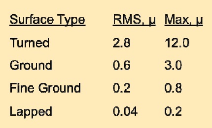 Figure 1. Differences in asperity dimensions based on root mean square (RMS) and maximum differences (in microns) in surface finish techniques (2).
Figure 2 describes the importance of surface finish, demonstrating the mean asperity height (r) and showing that the combined asperity heights (h) must be cleared in order to avoid adhesive or abrasive wear on one or both surfaces.
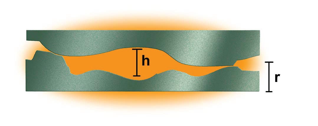 Figure 2. The relationship between combined surface roughness of two surfaces and film thickness requirement.
As surfaces are worked without a fully supporting film surface, damage occurs from abrasive and adhesive contact. In addition, the RMS and maximum asperity dimensions increase and surfaces progressively become more difficult to lubricate effectively.
Figure 3 shows the expected result that occurs to machine surfaces due to a combination of lubrication-related factors, some of which are avoidable with improved maintenance and design. Improved maintenance tactics alone do not overcome inadequate design.
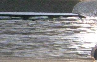 Figure 3. Surface of a rough gear flank from a wind turbine drive.
WORN SURFACES
Figure 3. Surface of a rough gear flank from a wind turbine drive.
WORN SURFACES
There are several lubricant companies that have developed additives with the intention of improving the surface smoothness of worn and rapidly degrading surfaces. For example, Lubrication Engineers (Monolec™ and Duolec™), BP Castrol (TGOA™ and MicroFlux Trans™), Whitmores (Eutectic™) and Schaeffer Manufacturing Co. (MicronMoly™). These organo-metallic oxide layer formation strategies replace traditional sulfur-phosphurous EP surface films, which is the traditional approach.
In addition, other companies have integrated surface enhancement into proprietary-formulated additives, with a similar mission of improving the surface finish through the application of chemi-physical reactions between the machine metals and the additive agents delivered to the machine surface through the lubricant.
As a career proponent of reliability centered lubrication practices, I have investigated the means and claims of surface protection through the chemi-physical work actions of specialized additive systems acting in conjunction with the normal stresses of the tribosystem. I have found these advanced technology approaches worthy of strong consideration, particularly for highly critical machines and for machines with a short mean time-to-failure as part of a systematic reliability plan. There are circumstances where neither of these strategies work or cannot work fast enough to resolve a developing problem.
NANOCOATING WITH METAL SILICATES
I once had a customer who reported repeatable and highly favorable results through the use of a different surface treatment approach. This method uses the existing machine lubricant to carry a silicate-based, metal treatment system to the work surface within the machine sump, much the way the blood stream carries antibiotics to specific locations of the body to halt disease. Rewitec is referred to as a nanocoating by its designer. It is based on the modification of the surface structure of rubbing machine surfaces that produces a metal-silicate surface layer. This reaction layer is somewhat like a ceramic surface in that it is hard and corrosion resistant. This metal-silicate layer delivers more favorable abrasion and wear qualities than nascent bare-metal grinding partners.
The active ingredient contains various silicates, as reported by the producer. The introduced solids produce a chemical reaction with the lubricated machine element (such as a gear, engine cylinder and bearing race) due to high partial pressure and temperatures during contact. The silicate atoms of the active ingredient conjoin with metal atoms of the metal surface and compose the ceramic-like metal-silicates layer. Figure 4 provides a graphic example of the metal-silicate layer.
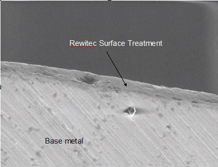
Figure 4. Ceramic-like metal-silicate layer formation produced by chemical reaction at a highly loaded machine surface.
Independent analysis of surface imprints using MuSurf (µSurf) Topometry by NanoFocus AG suggests appreciable change in surface roughness on worked surfaces following treatment. Figures 5 and 6 provide a contrast of surface profiles from a silicon imprint of the surface noted in Figure 3, contrasting change in condition through the nanocoating treatment.
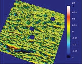 Figure 5(a). Wind turbine gear surface profile following use and before treatment.
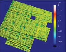
Figure 5(b). The identical cross section of wind turbine gear surface profile noted in Figure 5 following treatment.

Figure 6. Wind turbine gear drive flank after surface conditioning.
The blue square patches in the green area represent dust or contaminants on the samples that the software automatically extracted from measurement and comparison. The scale is noted on the right axis and ranges between 1 and -1 microns. The change in the roughness condition is noteworthy. This type of change has been duplicated in other test and operating conditions. Notwithstanding, measurement from operating machines suggests that oil film formation and surface protection increases following the nanotreatment.
For the sake of visual comparison, the gear flank shown for its roughness in Figure 3 is shown again beside the microtopograph in Figure 6.
Reliability Improvement Case Study No. 1 (Aggregates Shaker Screen Bearing). The screen is a Diester 8 x 20 HP Elliptical Shaker. The 25 HP electric motor operates at 1,784 rpm and the shaft rotating speed is 798 rpm. The shaker is processing aggregate at the rate of 600 tons per hour.
Machine health is measured using vibration analysis, including stress acceleration. Stress acceleration (Peak Vue) measurement is a preferred method for measuring surface contact energy, which is produced by poor quality oil films, rough surfaces and subsurface cracks, among other things. The machines have been under surveillance for some time.
The plot in Figure 7 shows the change in stress acceleration level on the bottom inboard bearing of a shaker screen in the axial position. Measurements shown in Figure 7 were taken in mid-May and then again in mid-July following treatment of the oil lubricated bearing, with the same oil in use. The operating load and speed is the same in both instances. The change in readings suggests a significant change in asperity (surface) contact rate following treatment.
 Figure 7. Stress acceleration readings reveal lower energy levels associated with surface roughness and oil fi lm effectiveness following treatment.
Reliability Improvement Case Study No. 2 (Jaw Crusher Shaft Bearing). This Jaw Crusher is a Hewitt Robins 50 x 62 model with a 450 HP motor operating at 1,198 rpm unloaded and a shaft operating speed of 188.8. This data was collected on the crusher at the inboard (flywheel) bearing position. There were eight positions collected, and six of the eight showed significant reduction in energy level, pointing to reduced contact energy. Operating load and speed conditions are the same during both measurement events.
Figures 8 and 9 provide plots of data comparing before and after treatment. Figure 8 is a regular vibration reading and Figure 9 is a stress acceleration reading. Both show significant change in energy level that is consistent with expectations promoted by the treatment supplier, Rewitec.
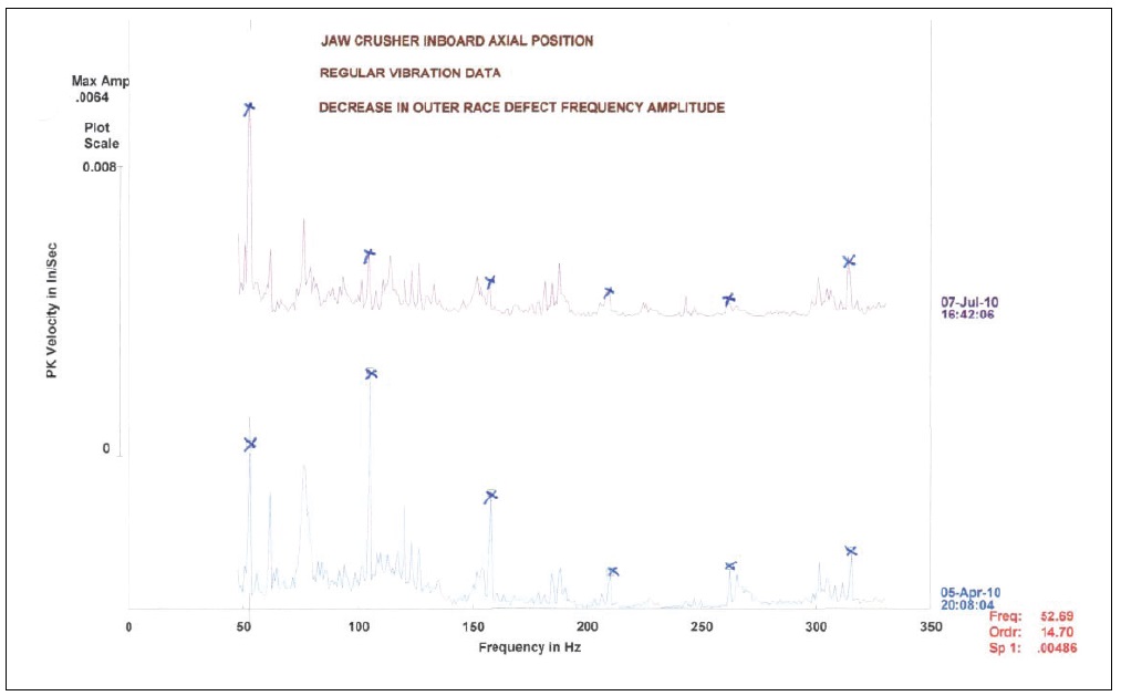 Figure 8. Overall vibration readings for the inboard shaft bearing.
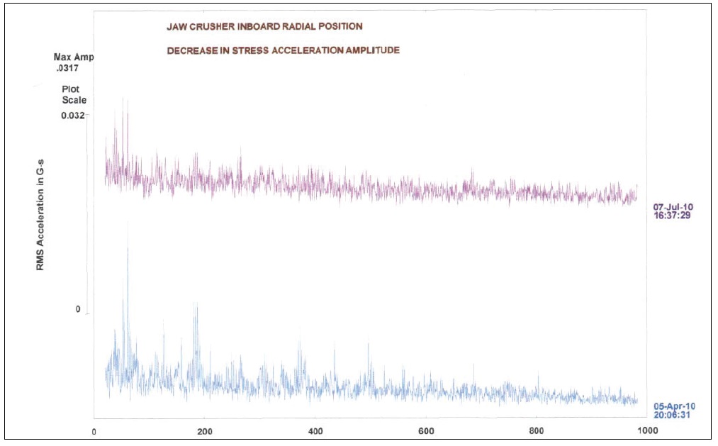
Figure 9. Stress acceleration readings for the inboard shaft bearing.
SUMMARY
Claims of superlubricants providing healing of lubricated component surfaces were met with open distain 20 years ago, some of which came from competitive lubricant suppliers. Measurement of results tended to be more subjective than objective, and to an extent the user was expected to believe in the change if a measurement was not feasible.
Measurement methods have improved, and a wealth of evidence now accompanies the scientific explanation of surface improvement. The examples noted in this article come with hard evidence of change by a combination of microtopographical measurement, stress acceleration measurement (aka compression wave analysis, Spike Energy, Peak Vue, Shock Pulse, etc.) and visual reflection.
As a reliability practitioner firmly engaged in progress through improvement in tribological profile of the machine components, I am interested in surface improvement opportunities. Whether one views the mechanism for this type of surface change as another form of chemi-physical tribo-film or not, it seems apparent that the produced effect by the silicate-based, metal treatment may measurably contribute to reduced surface roughness and machine stress.
One could expect that these effects would extend component lifecycles, at least for those components that have already advanced into a failure cycle.
REFERENCES
1.
Click here.
2.
Neale, M.J. (1996),
The Tribology Handbook, Second Edition, Butterworth-Heinemann, p. A7.2.
 Mike Johnson, CLS, CMRP, MLT II, MLA III, is the principal consultant for Advanced Machine Reliability Resources, in Franklin, Tenn. You can reach him at mike.johnson@precisionlubrication.com
.