Drying of coatings
Dr. Neil Canter, Contributing Editor | TLT Tech Beat April 2011
A new technique measures the stresses that occur during the drying process.
KEY CONCEPTS
•
Research has been conducted to determine how coatings fail during application.
•
In tracking the drying of a coating, a crack forms at the interface between the coating and the substrate.
•
Over time, the crack can get stuck until the stress forces it to resume moving in a zigzag, sawtooth manner.
In working on the surface, a lubricant, in effect, acts as a coating that provides lubricity, prevents welding and inhibits corrosion. Extending the operating life of a lubricant is a critical issue for those in industry involved in developing and using them.
In a previous TLT article, a new cerium oxide coating developed for use in power generation applications was described (
1). the coating displayed excellent resistance to oxidation in testing at temperatures between 650 C and 900 C for up to 4,000 hours.
One area that has not been examined is how coatings fail, particularly during their application. Eric Dufresne, the John J. Lee associate professor of mechanical engineering at Yale University in New Haven, Conn., says, “The crux of this issue is determining what happens when a liquid coating goes through a transformation into a solid coating. A first impression would suggest that the drying of a coating is no more than a phase transformation. In actuality, it is totally different because the drying of a coating is also a compositional change.”
Evaluation of failure in hard materials has been extensive. A previous TLT article discussed large-scale computer simulations done to show how cracks move through materials in three dimensions (
2). The result from this work shows that cracks move through materials in a helical fashion.
Dufresne asks why failure is not seen when a coating is drying, as it uniformly changes composition from a liquid to a solid. Rather, a coating failure occurs at a specific location through a peel or a crack.
Additional information explaining how failure takes place should be helpful in the preparation of more robust coatings. Such research is now being conducted.
TRACTION FORCE MICROSCOPY
Dufresne and his fellow researchers have studied the drying of an aqueous suspension of 11 nanometer silica particles onto a silicon elastomer with a thickness of 45 microns. He says, “We decided to use silica to coat the silicon elastomer because we anticipated that the silica will crack and peel on that substrate. Silica is designed to coat cardboard panels effectively. One other factor is that the substrate is transparent, so we could look right through it.”
The researchers used a technique known as traction force microscopy to measure the stresses that occur during the drying process. Dufresne says, “This method was originally developed by cell biologists to measure the force a live cell generates after it starts to crawl on a surface. We modified it to better understand what happens when coatings dry.”
The silica suspension had an initial concentration of 20% by volume (40% by weight). After drying, the concentration increased to 60% by weight, according to Dufresne. Yellow-green fluorescent microspheres with a diameter of 0.1 micron were incorporated into the dispersion at a concentration of 0.1%. they were used to visualize the deformation of the coating as it dries.
To simplify this complicated process, the coating dried onto one wall of a capillary tube containing the silicon elastomer substrate. Dufresne says, “We decided on this approach so we could more easily track the three-dimensional displacements of tracer particles.”
In this fashion, all of the fluid used to carry the coating will dry at one end of the capillary tube. Dufresne indicates the fluid will dry in a non-uniform manner with a higher concentration at the surface forming a thicker skin. He adds, “This process is driven more by fluid evaporation than by diffusion.”
The researchers used time-lapse, three-dimensional confocal microscopy to track the motion of the fluorescent particles. In this process, laser lines at 491 nanometers and 561 nanometers were used to track the fluorescent beads in the suspension and the elastomer, respectively.
As the coating started to dry, the researchers found that a crack forms at the interface between the coating and the substrate. This crack also deforms the silicon elastomer substrate. Dufresne says, “In setting up the drying and boundary conditions, the crack can get stuck for a while, but then stress will build up forcing the crack to resume moving.”
Figure 1 shows an image of the fluorescent tracer particles on the coating as it peels. The curve is a plot showing the stress on a single tracer particle at a specific time.
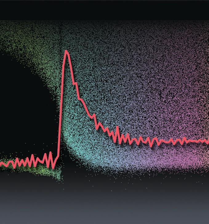 Figure 1. Fluorescent tracer particles were added to an aqueous suspension of silica particles to track the drying of the coating on a silicon elastomer using time-lapse, three-dimensional confocal microscopy. (Courtesy of Yale University)
The researchers found that the crack moves through the coating in a zigzag, sawtooth manner. Dufresne says, “This process is done in a smooth fashion as the crack moves over time.”
Dufresne says the rate of loading of the coating does not affect the development and movement of the crack. In this case, the researchers found that the crack front moved at a velocity of 460 nanometers per second.
The drying of the coating is a big mechanics problem, which relates the stress of the coating onto the substrate. At each moment of the drying, the stress profile can be measured.
Future work will involve evaluation of the drying of a coating at a much higher solids loading. This work was conducted with an aqueous coating, but Dufresne believes it also can be used to evaluate the drying of oil-based suspensions.
Additional work will be done to look at the microscopic properties of the solids as they dry. Dufresne would also like to use this experimental approach to study how biological coatings such as skin protect against stresses.
Further details on this research can be found in a recent article (
3) or by contacting Dufresne at
eric.dufresne@yale.edu.
REFERENCES
1.
Canter, N. (2010), “Oxidation-Resistant Metal Coatings,” TLT,
66 (11), pp. 10–11.
2.
Canter, N. (2010), “Crack Formation in 3D,” TLT,
66 (7), pp. 8–9.
3.
Xu, Y., Engl, W., Jerison, E., Wallenstein, K., Hyland, C., Wilen, L. and Dufresne, E. (2010), “Imaging In-Plane and Normal Stresses Near An Interface Crack using Traction Force Microscopy,”
Proceedings of the National Academy of Sciences,
107 (34), pp. 14964–14967.
 Neil Canter heads his own consulting company, Chemical Solutions, in Willow Grove, Pa. Ideas for Tech Beat items can be sent to him at neilcanter@comcast.net
.