Oil analysis in the real world: Part VII
Jack Poley | TLT On Condition Monitoring March 2011
A three-tiered system is the most effective methodology.
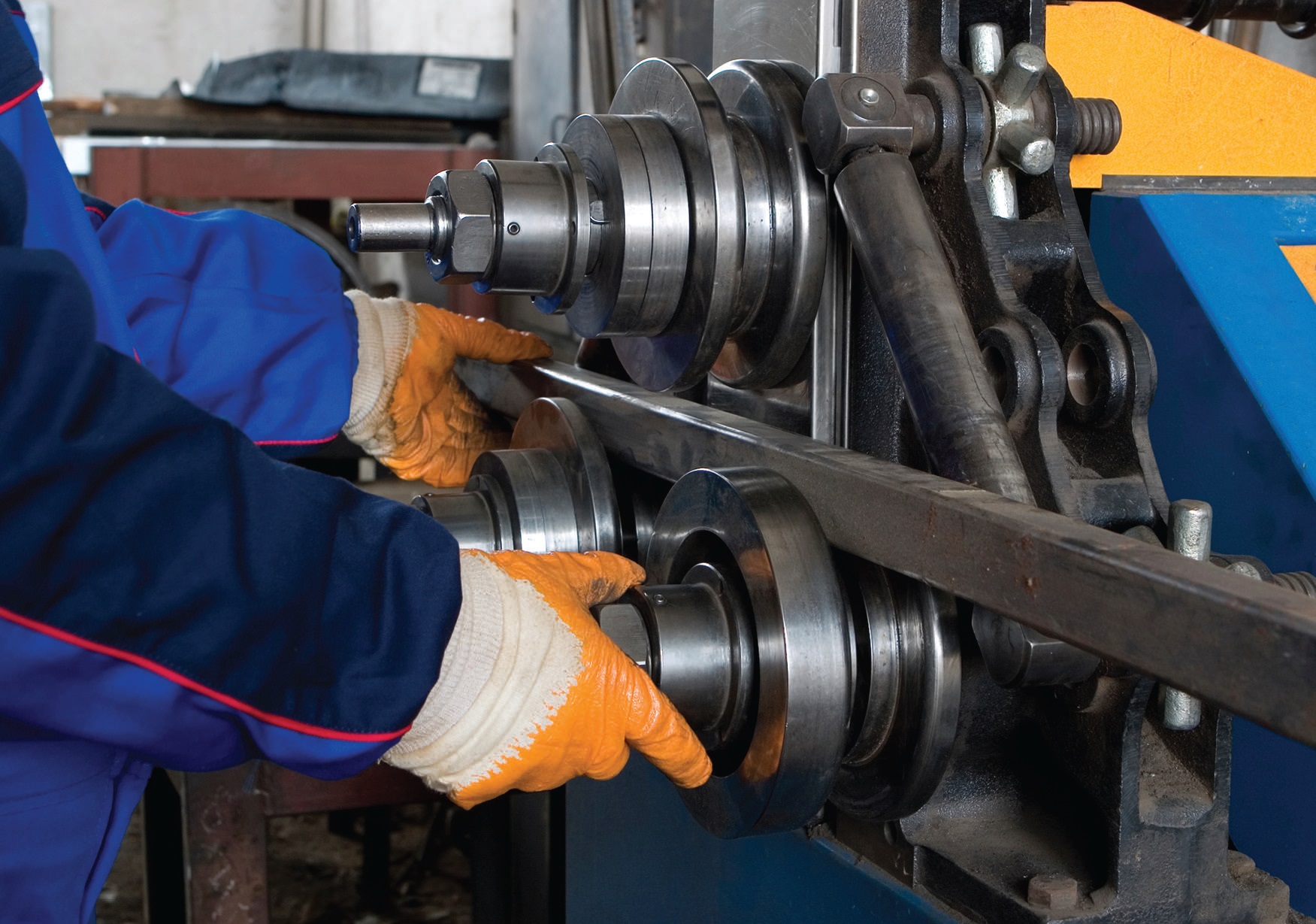
www.canstockphoto.com
So far I’ve provided testing packages for a variety of component types with the goal of detecting trauma possibilities within the scope of oil analysis capability. Results should be disclosed in sufficient time to take remedial action at reasonable costs, including the generation of corroborating tests with minimal redundancy. The assumption is that full-service laboratory testing is employed.
While full-service testing is best in terms of information gleaned, it’s not always complete medicine given the component’s application/setting and the technological developments in oil analysis now available.
Following is a three-tiered system for modern oil analysis in the 21st Century:
•
Tier 1:
Online sensors (first alert, first defense).
•
Tier 2:
Onsite backup and vetting tests (rapid assessment).
•
Tier 3:
Offsite full laboratory capabilities (thorough but slow due to transportation issues).
The technical gains made in Tiers 1 and 2 in the last decade have now presented the maintenance community with variety of options. I discussed some of these options in a generalized sense in previous columns, and we’ll now look at some specific applications and their typical environments. Note that the environment of a machine makes a huge difference in how it might best be monitored or, for that matter, whether it should be monitored at all.
OVER-THE-ROAD TRUCKING
U. S. railroads were the first to adopt modern oil analysis for their prime movers, followed by the U.S. military, which focused on single-engine jet aircraft. OTR was the third most sizeable market for oil analysis and began to heat up by the mid-1960s.
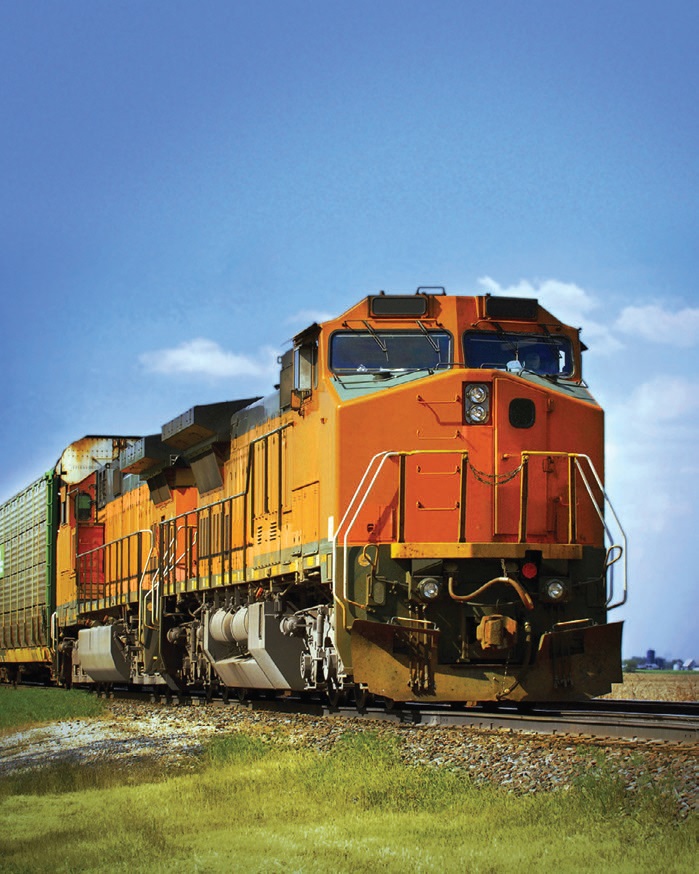 www.canstockphoto.com
Diesel engines are the dominant components sampled, although some users monitor transmissions and differentials, as well. While the major fleets achieve the most benefits,* smaller fleets benefit proportionally so that the ROI model works, as it always does, no matter how many units are monitored. While different maintenance and lube management philosophies are clearly in play, oil analysis continues to thrive in the OTR market.
*
Larger fleets of equipment have a distinct advantage in being able to spot problem areas or trends, e.g., specific OEM models that show a propensity for fuel or coolant leaks, either from manufacturing issues or possibly from lack of sufficient training in servicing and maintaining such components.
OTR APPLICATIONS
OTR operations are the most benign of the applications I’ll discuss, but there are still plenty of potential failures to avert. Here are some useful considerations:
•
Operating conditions are usually moderate (choose a term).
•
Abrasives are usually not prevalent in the engine’s combustion air supply so that careless oil handling and storage practices are the primary concern for this contaminant. With gearsets, a breather may be bypassing.
•
There are three primary contaminants from issues in the engine:
1.
Fuel from a fuel leak: pump, injector, jumper line.
2.
Fuel soot (
see below).
3.
Coolant leakage: oil-cooler pinhole, injector seal, gasket.
•
Fuel soot and oxidation are indicators that, when limits are reached, suggest an oil drain. If the limits are reached too fast, there may be operating issues.
1.
Fuel soot (diesels only)
a.
Fuel mixture too rich
b.
Worn rings
c.
Excessive engine idling or lugging
d.
Dribbling injectors or seal leaks (injector or pump).
2.
Oxidation
a.
Oil has reached drain limit in normal fashion
b.
Oil has reached drain limit too rapidly, suggesting problems from higher-than-normal temperatures.
o
Clogged breather (differential, trans)
o
Engine overload (excessive payload)
o
Wrong viscosity oil added
o
Wrong oil for the application.
•
Water. Of concern when present, it is usually from taking a cold sample or some other sampling issue. Combustion water vapor and normal overnight condensation will usually evaporate due to normal crankcase temperature. While water could accompany a glycol/coolant leak, such an occurrence, given a proper sample, is rare and would suggest a massive coolant leak such that simple observation of the dipstick would show an overfilled crankcase or bubbles on the end of the dipstick from the water, possibly milkiness as well.
•
High-speed diesel engines. Those used for OTR do not typically generate significant quantities of large wear particles (5μ or greater) like their slower-speed brethren so that particulate inspections such as particle count (PC) are usually not of great value.
Corollary No. 1: Most OTR trauma provides a greater window between detection and failure compared to other applications, with the possible exception of coolant seepage. This characteristic suggests that Tier 2 testing is not particularly essential (justifiable) for the OTR application.
•
The current atmosphere in OTR is to enjoy extended drains when safely achievable, reducing oil and disposal costs. This notion has had an accelerated interest in the past decade because the advent of sulfur minimization-to-elimination has made extended drains increasingly possible, coupled with continuing advances in the manufacture of lubricants.
Corollary No. 2: There is a reasonable possibility for Tier 1 (sensor) testing using an oil-condition sensor. Unfortunately, sending samples to an offsite lab means that the time consumed with sample taking, submission, testing and then reporting back to the user renders an extended drain assessment after-the-fact. This means that the only way to participate in extended drains, if Tier 3 is the singular option employed, is to not drain the oil and
hope that the report justifies the decision.
If a drain is required, bring the engine to another shop down the road and perform the drain. There isn’t a lot of risk in this process, but there is a lot of inconvenience (somehow inconvenience often translates to money). One could, of course, abandon extended drain pursuit, but why leave that money on the table if a strong alternative is available?
OIL-CONDITION SENSORS
Most oil-condition sensors work on the principal of dielectric strength measurement where it is well understood that contamination and other impurities in the lubricant will change the conductivity of the lube, causing a sensor properly positioned in the oil circuit to change its output relative to its baseline voltage. This change, while not identifiable as to the nature of the event itself, does have a value expressed in voltage change, and that voltage excursion can represent possible trauma.
All the parameters discussed earlier—fuel, fuel soot, water, glycol, etc., even additive depletion—can result in sensor output variance that provides a first alert as to such events:
•
The primary benefit is that a steady-state output from the sensor suggests no issues with the oil condition, therefore there’s no apparent reason to change the oil.
•
A secondary benefit is the immediate detection of a problem such as a coolant leak, which is potentially fatal. Suppose this detection occurred almost immediately after the previous Tier 3 lab test? One would have coolant in the lube for at least 30/45/60/90 days, dependent on the sampling frequency employed. Such early detection could easily save an engine.
Perhaps the secondary benefit is as good as the primary benefit.
Following is a summary of OTR monitoring using a three-tiered oil analysis system:
•
Minimum Tier 3 testing for OTR:
1.
Spectrometric metals analysis (any component)
2.
Viscosity (any component)
3.
Infrared Spectroscopy (FTIR)
a.
Fuel soot (diesel)
b.
Oxidation (any component)
c.
Glycol (diesel)
d.
Water (if not employing a crackle test)
4.
Fuel dilution (diesel)
5.
Particle count (auto-powershift transmission)
•
The addition of Tier 1 for practical oil-drain extension and first-alert detection of lube parameter changes can indicate possible trauma: consider an oil-condition sensor to achieve such benefits.
In subsequent columns, we’ll explore more rigorous or specialized applications.
 Jack Poley is managing partner of Condition Monitoring International (CMI), Miami, consultants in fluid analysis. You can reach him at jpoley@conditionmonitoringintl.com
.
For more information about CMI, visit www.conditionmonitoringintl.com.