Monitoring metalworking fluids
Dr. Neil Canter, Contributing Editor | TLT Cover Story March 2011
A host of testing methodologies can extend the life of your fluids—and your customer’s machinery.
KEY CONCEPTS
• MWF monitoring is extremely important to optimize performance and extend fluid life.
• The most important test is concentration because fluid systems are not static and individual formulation components deplete at different rates.
• Some tests used to monitor MWFs need to be upgraded to shorten the analysis time and improve accuracy and precision.
Metalworking fluids (MWFs) can be complex formulations containing a variety of additive types to ensure optimum performance. Among the functions expected of MWFs are providing lubricity, cooling, corrosion protection, prevention of welding and flushing metal chips.
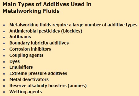
The types of additives used in a MWF are listed in Table 1. Much is expected of the fluid even before a consideration is made about its operating environment. Contaminants such as microbes and tramp oil easily can enter MWF systems and will accelerate degradation over time.
Table 1. MWFs can be formulated with the wide range of additives shown. Additive selection is based on fluid type and application. (Courtesy of Chemical Solutions)
For this reason, it is important to monitor the condition of a MWF over its operating life to ensure the performance can be maintained at as high a level as possible. An assessment of the test procedures used to evaluate MWFs is provided in this article from the standpoint of the additive supplier, MWF formulator, testing lab and end-user.
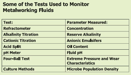
With the complexity of MWF systems and problems, a large number of tests covering a wide range of parameters can be run. Some of the key tests are shown in Table 2. This article reviews tests used to monitor MWFs and focuses on the development of several new procedures that can provide more accurate data in a faster time frame.
Table 2. Some of the key tests used to monitor MWFs and the parameters they measure are shown. (Courtesy of Chemical Solutions)
CONCENTRATION
STLE-member Andy Nelson, president of ANR Engineering Ltd. In Perrysburg, Ohio, says, “MWFs in general are a compromise both in their formulation and application. On the most basic level, a water-miscible MWF is a compromise in that it must be a stable concentrate capable of being stored at high temperature in Nevada and on a loading dock in Minnesota in the middle of winter. In spite of these temperature contrasts, MWFs must still exhibit the desired characteristics after further dilution with water.”
Nelson then indicates the challenges for a MWF during continued use: “When the fluid is applied (most end-users want only one or at most two fluids for the whole shop), the end-user asks that 3% to 10% of the concentrate convert water into this magic fluid that will optimize the performance of heavy-duty broaching, high-velocity turning and Blanchard grinding. To have any hope of success, it is critical that the fluid be maintained at the proper concentration.”
It is also critical to understand that these fluids fulfill many different functions, including improving surface integrity and the metal-removal process, moving chips out of the cutting zone and providing in-process corrosion protection. The non-cutting considerations include things such as residue characteristics, length and type of corrosion protection, working odors and mists, biological stability, chemical content and disposability, just to name a few. MWFs seldom accomplish just one function.
To determine the optimum working concentration for a specific fluid and a specific operation, it is necessary to do a series of experiments and/or go by previous experience. Nelson says, “Controlling the concentration is critical, and to control anything you must be able to measure it. The problem with measuring MWF concentration starts once the concentrate is diluted with water prior to use.”
Nelson believes the individual components in the MWF start to deplete at different rates, so exactly what the concentration is becomes a guesstimate. “Additionally, these fluid systems are not static and are in a constant state of change,” he says. “It is therefore critical that the concentration of the system be closely controlled, and to do that it must be accurately measured.
There are basically four ways of checking concentration: measuring the refractive index of the mixture; titrating for alkalinity, sulfonate or some other property; acid or salt split; and depletion analysis or the measurement of the individual chemical components in the fluid. They each have advantages and disadvantages.
Nelson says, “Measuring concentration by refractometer is fast, easy and can be conveniently done on the shop floor. The conventional analog refractometer does a pretty good job of estimating concentration and provides additional subjective information about tramp oil and emulsion stability. The newest generation of digital refractometers is both more accurate and much more repeatable than analog refractometers.”
In addition, digital refractometers have their own light source and evaporation shield and measure the light as it refracts off of the surface of the fluid. This means that many of the sources of error have been eliminated in these new instruments.
In a given application, the MWF is designed to operate at a specific concentration range recommended by the supplier. Nelson says, “In an average machine shop, an end-user will use a refractometer to check the concentration of MWF systems maybe once a week, which is often not enough!”
A refractometer measures concentration by determining the refractive index of the fluid. The primary type used is an analog unit (see Figure 1). Light is exposed to a drop of the MWF placed on one side of a glass prism. The light moves through a prism optical wedge and is then focused by a lens on a number scale read by the user. The reading represents the ratio of the velocity of the light moving through the sample as compared to the light moving through water.
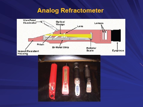
Figure 1. Analog refractometers provide an easy and rapid way to measure the concentration of MWFs. (Courtesy of STLE)
Lab bench and hand-held units are both available. Nelson indicates that it is important for the refractometer to have temperature compensation. There is an indirect relationship between the reading and temperature. Nelson says, “Some cheaper, hand-held refractometers may not include temperature compensation.”
Calibration of the analog refractometer is also important but is usually done only after the first time the unit is used, Nelson says, while manufacturers recommend calibrating before each use. This can lead to very inaccurate concentration measurements.
An analog refractometer does have some disadvantages. Nelson adds, “Measurement of concentration is less effective when the MWF is contaminated with tramp oil and operates under hard-water conditions. The number scale may also be blurred, making an accurate reading difficult.”
Third-generation digital refractometers (from suppliers such as MISCO) have recently become available to the MWF industry over the past few years (1). Nelson says, “Digital refractometers are better able to handle measurement of MWF concentration under more adverse conditions. A sample is placed in a well and the reading made from below. This method reduces the interference of tramp oil, which floats to the top of the sample.”
The digital unit generates a specific value so the user does not have to use an internal scale to determine the concentration. An additional benefit is that the digital unit can be programmed so that the value obtained is the actual concentration of the fluid. In the analog refractometer, the value determined from the internal scale is measured in Brix and must be converted to a concentration figure through a scale, factor or chart provided by the MWF supplier.
The digital unit is equipped with temperature compensation sensors and will not take a reading until the fluid temperature is equal to the temperature of the stainless steel housing that holds the sample. Nelson also indicates that the unit does a better job of minimizing problems with water evaporation than an analog refractometer.
Both lab bench and hand-held digital refractometers are available for use. Figure 2 shows a hand-held unit.
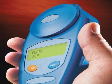
Figure 2. Digital refractometers are better able to handle the measurement of MWFs under more adverse conditions. They also provide better accuracy and precision than analog refractometers. (Courtesy of MISCO Refractometers)
The accuracy and precision of a digital refractometer is between +/- 0.1 and 0.2 Brix units. The best analog units have an accuracy and precision of +/- 0.2 Brix units.
Nelson offers a case study that examines the value of using a digital refractometer. The study involves an emulsified oil containing a high level of tramp oil. The virgin fluid is diluted to an initial use concentration of 10%.
Nelson explains, “In this particular case, the amount of tramp oil entering the MWF system increased to the point that it represented 90% of the total MWF content. The end-user was confused because he was told his problem was not due to concentration.”
He continues, “The analog refractometer could not provide an accurate reading because the internal scale was fuzzy. In contrast, the digital refractometer was much more effective and provided accurate concentration readings up to levels of 50% tramp oil.”
WET CHEMICAL AND INSTRUMENTAL TESTING
While a refractometer is the most important test to monitor the condition of a MWF, other procedures are used to examine specific fluid components. Tests can be placed into the categories of wet chemical titrations, instrument analysis and performance tests.
The first category covers the evaluation of the acid number and reserve alkalinity of the MWF and the determination of the content of anionic surfactant through an actives titration. A test that also can be placed in the wet chemical category is to determine oil content through treatment of the fluid with mineral acid. This acid split technique provides a quantitative measurement of free and entrained mineral oil.
The reserve alkalinity, anionic surfactant determination and acid split tests provide a measure of the concentration of specific components used in formulating the MWF. They complement the results obtained from the refractometer.
The primary instrument test is a pH meter to determine the pH value of a water-based MWF. Most MWFs are designed to operate at a pH range around 9. Deviations from this value will indicate to the user that the MWF is facing contamination and may be starting to deteriorate.
Instrument analysis determines if a specific component in a MWF has been depleted or if a new component is present that might suggest the fluid is starting to deteriorate. Testing methods include:
• Infrared analysis, which looks for specific functional groups in the components formulated into the MWF.
• X-ray fluorescence, which focuses on detection of specific elements such as sulfur, chlorine and phosphorus.
• Elemental analysis by such techniques as inductively coupled plasma (ICP) that detects a wide range of metals that may be contaminating the MWF.
Performance tests evaluate a specific property of a fluid such as its extreme-pressure characteristics, foam profile and corrosion protection. The first parameter can be measured through the use of a machine such as the Pin and Vee Block or Four-Ball tester. Foam is a critical characteristic, and there are a variety of techniques used to evaluate it, including shake foam, recirculation and wear blender tests. Corrosion Protection is evaluated by use of the cast-iron chip test.
Further details on these tests can be found in the book MWFs: Second Edition, published in 2006 (2).
With a wide variety of tests and a large number of MWFs used in the marketplace, the question of which tests to use for a specific MWF in a particular application comes to mind. Chris Fink, lab manager for Engineered Lubricants Co. In Maryland Heights, Mo., says, “In evaluating MWFs, it is important to know what fluid type is being examined. We have two basic formats. There is one for oil-based products and one for water-based products.”
For oil-based MWFs, Fink indicates that his lab has a basic testing format. “We evaluate oils for viscosity, total acid number, copper strip test, infrared analysis, elemental analysis (by ICP and XRF) and wear analysis using the Multi Four-Ball Tester,” he says. An image of the tester is shown in Figure 3.
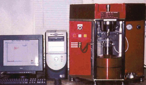
Figure 3. The Multi Four-Ball Test Machine incorporates both the four-ball EP and wear testers into one computer-operated instrument to measure the extreme-pressure and wear properties of a MWF. (Courtesy of Engineered Lubricants Co.)
Some of the same tests (infrared analysis, four-ball wear testing and elemental analysis) also are useful for water-based fluids. Fink adds, “We find that determination of pH, cast-iron chip testing, foam testing and metal coupon testing also are required.”
In assessing the potential performance of a new MWF, Fink indicates several tests are very useful to predict performance. “Elemental analysis, an infrared scan and wear testing are the most valuable tests,” he notes. “These analytical tests give a quick basic look at the structure of the product and how it performs in the field.”
Evaluation of a used MWF is more complex because there could be a number of reasons why the fluid is not performing at an optimum level. Fink says, “The concentration ratio in water-based fluids and the combination of pH, bacteria and fungal dip slides, ICP and the cast-iron chip test give a good indication of the condition of the used fluid. However, it is best to set the system up on a routine sampling schedule so you can track the life of a MWF. In this way, a customer can maintain the fluid under optimum conditions.”
Fink offers an example of how several tests were needed to solve a specific MWF problem. “Recently, we had a customer using an oil-based chlorinated product for stamping and forming cold-rolled steel and aluminum parts,” he says. “Their problem was staining and rusting of stacked parts.”
The customer perceived that a non-chlorinated product would be needed, so the challenge was developing a product that maintained the extreme-pressure performance of the current product while eliminating the stain and rust problems. Fink indicates that several test procedures need to be run in the development of a new product.
“We needed to try several extreme-pressure additives in combination to achieve this goal while maintaining the same product viscosity,” he says. “Numerous tests were run on the Multi Four-Ball tester to find the proper combination and concentration of extreme-pressure additives. In addition, corrosion testing was conducted in the humidity cabinet to ensure that the product did not stain or rust aluminum and steel parts.”
MICROBE POPULATION DENSITY
Determining the extend of microbial contamination in MWF systems is a priority because microbes such as bacteria and fungi are known to not only cause MWFs to decompose, leading to premature failure, but also to cause health and safety problems. Many of the problems faced by end-users are discussed in a recent TLT feature article (3).
An example of how microbes can cause problems is the image of the formation of a biofilm shown in Figure 4. Biofilms are communities of microbes that become established on MWF system surfaces to utilize the components of the fluid as food.
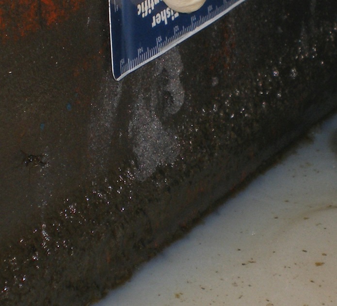
Figure 4. Microbes can cause problems in MWFs systems by forming biofilms such as the one found here on the wall of a sump just above the MWF surface. (Courtesy of BCA Inc.)
STLE-fellow Dr. Fred Passman, president of BCA Inc. in Princeton, N.J., says, “This biofilm was found on the wall of a sump just above the MWF surface. In this zone, MWF splashes onto the sump walls, replenishing water and nutrients that enable the microbes to continue growing. The biofilm continues along the tank wall below the MWF surface.”
There are a number of test procedures used to measure the population density of microbes. Passman says, “The primary test is to culture the microbes by adding a sample of the fluid to a dip slide and then incubating it. Over time, the microbes present will grow, and the user will then see the extent of fluid contamination.”
This test is easy to use and inexpensive to run. Both bacteria and fungus can be detected as the dipslides contain media to grow both microbes. The microbes form colonies that are detected by the user. Results are reported in colony-forming units per milliliter. Passman says, “One of the biggest problems with the test is that it can take at least 24 hours and sometimes a week or longer to detect colonies. Each colony represents a billion cells or 30 generations of microbes.”
In many cases, MWF end-users need results much more quickly. Three other tests provide faster feedback. The catalase test introduced in 1981 measures the amount of oxygen gas generated when a MWF sample is treated with hydrogen peroxide. Catalase is an enzyme known to be present in aerobic bacteria and all species of fungi.
Passman says, “The amount of oxygen generated is roughly proportional to the biomass in the sample. This test can be conducted in 15 minutes, either in a lab or at the location of a MWF system but does not distinguish between bacteria and fungi.”
A second technique involves measuring the change in the amount of dissolved oxygen in a MWF sample after shaking it. Passman says, “I prefer to let the sample sit for two hours and then measure the change in the dissolved oxygen concentration. This test can be performed in the field, but it also only detects aerobic microbes and does not differentiate between bacteria and fungi.”
A third test measures the concentration of adenosine triphosphate (ATP), the main energy carrier present in all living things. In a manner of only a few minutes, a new procedure has recently been developed to measure the concentration of ATP in a MWF sample (4). This technique was developed by the Canadian company LuminUltra™ Technologies Ltd. In Fredericton, New Brunswick.
The procedure takes advantage of the reaction of ATP with the enzyme substrate complex Luciferin-Luciferase. Passman comments on the procedure, “The ATP test provides data as quickly as many of the tests that have been used historically to do MWF condition monitoring. This translates into an opportunity for real-time control and substantially more cost-effective fluid management. Because it detects all metabolically active microbes in the sample, it provides an accurate measure of both total biomass and the biomasses biodeteriogenic (damage-causing) potential.”
The ATP test has been approved by ASTM and is designated as E2694. This method can be run both in the lab (see Figure 5) and in the field. A full interlaboratory study during which 10 participating companies tested 22 emulsifiable oils, semisynthetic and synthetic MWF samples was recently completed. The results, which show excellent repeatability and reproducibility, will be reported in a manuscript being prepared for publication in STLE’s peer-reviewed journal, Tribology Transactions.
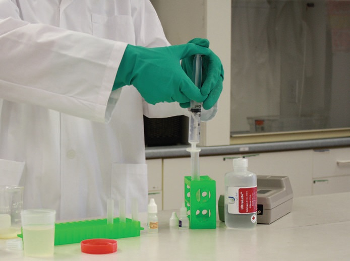
Figure 5. A new ATP test has just been approved by ASTM to measure the microbe population density in a MWF system. (Courtesy of LuminUltra™ Technologies Ltd.)
Passman anticipates that a polymerase chain reaction (PCR) field method may become available sometime within the next decade. PCR creates many copies of specific DNA fragments. This technique can be used to prepare and analyze genetic material from the various microbes present in a sample. Once identified, the user will then know which microbes are present.
Passman says, “PCR methods are continuing to evolve at a good pace. A reliable field method may be available for use In the future. For now, PCR requires expensive instrumentation and skilled technicians to perform. Keep in mind that it took nearly 60 years to get the ATP test from its original form to one usable for MWF analysis.”
ANALYSIS OF SURFACTANTS
For most water-dilatable MWFs, particularly those that form emulsions, surfactants are key components needed to stabilize the formulation. With the many different types of surfactants available, it can be difficult for a MWF formulator to determine how to evaluate them if they run into formulation or performance problems.
STLE-member James Stephens, business manager for Clariant Corp. in Mt. Holly, N.C., says, “Surfactants are diverse, which makes it very difficult to evaluate them. We evaluate their properties from both an instrumental and a wet chemical standpoint.”
Instrument testing includes multinuclear NMR (nuclear magnetic resonance) analysis, infrared analysis, HPLC (high pressure liquid chromatography) and GC/MS (gas chromatography/mass spectroscopy). Stephens adds, “We utilize proton, carbon-13 and phosphorus-31 NMR because these techniques help to determine the structure of the surfactants.”
HPLC and GC/MS are both separation techniques, especially useful at detecting contaminants in surfactants and, as a consequence, assessing their purity. Both methods involve mixtures in a mobile phase passing through a stationary phase. Components in the mixture travel through the stationary phase at different rates, thereby becoming separated. In HPLC the mobile phase is a solvent or solvent mixture, while for GC/MS the mobile phase is a gas such as nitrogen. An added value of the latter technique is that the isolated components can be analyzed by mass spectroscopy to expedite their identification.
Besides acid number, wet chemical procedures used to examine surfactants include cloud point, hydroxyl value and saponification number. Cloud point is a particularly useful method that evaluates the solubility of a surfactant in water, salt solutions and various solvents. This parameter is defined as the temperature at which the surfactant becomes insoluble in a specific solvent.
Hydroxyl number and saponification value are both used to determine the extent of the reactions of specific esters, a major class of nonionic surfactants. The former is also used to assess the composition of other nonionic surfactant types.
The time-consuming and variable nature of several of these techniques has led to upgrades that improve accuracy. Stephens says, “Determination of hydroxyl numbers is a time-consuming process that can be replaced with in-process near infrared analysis. Cloud point testing also can be very subjective depending upon the operator. We have found that instrument analysis using light transmittance has minimized variability.”
For field problems with surfactants, Stephens looks to work with a number of techniques to check composition and for contaminants. He says, “We first start with a basic infrared analysis. Additional testing by GC/MS easily can detect any impurities or contaminants. We also look at various NMR techniques to check for structural irregularities.”
MACHINING TESTS
The prior test methods discussed are used to evaluate the MWF or components incorporated into the MWF. There are also test procedures used to monitor the effectiveness of the machining operation.
STLE-member Gary Rodak of Machining Efficiencies, Inc. in Gregory, Mich., says, “Tool wear and surface finish evaluations typically describe the quality of the parts produced. Tool wear patterns identify the overall performance of the machining process. Monitoring tool wear patterns enable the machinist to recognize machine vibrations due to incorrect setup conditions, high heat due to improper aim of nozzles or excessive tramp oils, sediment issues and other suboptimized conditions.”
The movement of the MWF industry to high-speed machining was discussed in a past TLT article (5) and presents another set of challenges in detecting machining problems (see Figure 6). Rodak says, “In high-speed machining situations, tool chatter is very destructive. The tool wear pattern that indicates chatter is very obvious on the tool edge and in the remaining part micro-finish. A modal analysis test of the rigidity of the machining setup, part and fixture will identify the optimum combination of depth of cut and revolutions per minute that would be suitable for stable machining. An acoustical analysis may indicate when the machine setup is chattering.”
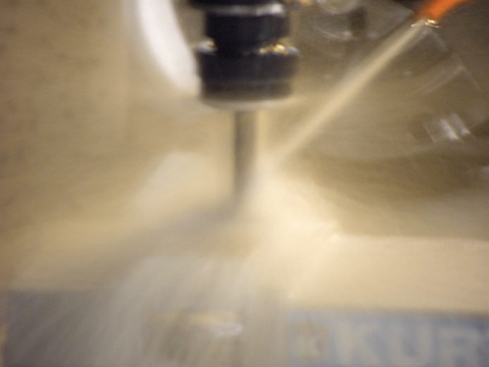
Figure 6. High-speed machining is monitored through evaluation of a tool wear pattern, acoustical analysis and a modal analysis test. (Courtesy of Machining Efficiencies, Inc.)
Other variables that need to be checked in high-speed machining include the tool holders, tool materials and MWF. Rodak explains, “There is more to high-speed machining than surface speed. The tool holders must be HSK style E or F to eliminate vibrations and toolholders should be shrink-fit style.”
He continues, “Tool material and coatings limit the upper temperatures that the cutting tool can tolerate. High-pressure MWF coolant delivered through the tool to the cutting zone keeps the tool edge temperatures in an operable range. Cryogenic lubricants such as carbon dioxide are being developed to reduce cutting zone temperatures.”
END-USER PERSPECTIVE
STLE-member Lloyd Lazarus, staff engineer for Honeywell Federal Manufacturing & Technologies LLC in Kansas City, Mo., is responsible for maintaining MWF in one 7,000-gallon central system and 100-150 machine sumps ranging in volume from one gallon up to 100 gallons. He says, “We need to take care of a large number of MWF systems that contain several different MWF types that are oil- and water-based.”
The plant is run on a two-shift, five-day schedule. During off-shifts and weekends, the central system is run for 10 minutes every two hours to minimize the potential for growth of anaerobic microbes.
Many of the operations are done in machine centers that conduct profile and plunge milling, boring, drilling, gun drilling and reaming operations. Lazarus notes that many of the production runs involve small quantities of parts.
In monitoring MWFs, much of Lazarus’ attention is spent on the central system. He says, “The refractometer is our primary method for measuring the concentration of the MWF. We check pH when checking concentration. We run an alkalinity titration, do an acid split, determine dissolved oxygen and conduct water-hardness tests using dipsticks on a weekly basis.”
With the municipal water having hardness between 80 ppm and 120 ppm and his use of make-up water treated by reverse osmosis, Lazarus does not bother with measuring conductivity. Refractometer, pH and water-hardness dipstick testing is done 2-3 times per week on the central system. The acid split procedure is usually run once a week.
A proprietary biocide test is conducted on the central system to determine the concentration of biocides, bacteria and fungus. This colorimetric procedure is used twice a week. Dip sticks are incubated every two weeks to determine bacteria and mold counts.
For many of the higher capacity, stand-alone machine sumps, concentration is measured by refractometer about once a week. Lazarus indicates that 60% of these sumps hold fewer than 50 gallons, so it is not time effective to do additional testing.
One of the most useful tests run by Lazarus is the acid split procedure. He says, “Our central system runs at a high velocity and mechanically retains a lot of oil. We need the data from the acid split procedure to indicate whether excessive oil may have entered the system from a hydraulic fluid leak.”
Above all Lazarus stresses the need to keep records on MWFs systems that include all of the data obtained on a daily basis plus any pertinent observations. “The objective is to use this data to pick up trends about the condition of the fluid in order to take action before major problems occur,” he says. “In addition, we use this data to make sure we do not repeat mistakes made in the past.”
Lazarus maintains that such an approach is really only worthwhile for a large central system. With smaller machine sumps, it is simply not worth it.
In the case of a machinist turning on a small system and detecting an odor problem that may suggest the MWF is spoiled, Lazarus suggests that the sump be run for a little bit. If the odor persists, the system is dumped, flushed and refilled.
UPGRADING TESTS
Some of the current test methodology needs to be upgraded, either because the current procedures are too time-consuming or there are problems with accuracy and precision. In the case of lengthy testing, results are needed very quickly so that the appropriate measures can be taken to address a specific MWF system problem. Any lengthy delay may serve to only make the problem worse.
Nelson raises concerns about the need for new test methods to evaluate several important parameters used to evaluate the MWF condition. He says, “One of the big issues is finding a way to speed up the procedure run to determine the population density of fungus in a sample.” The standard dip slide procedure can take three days to determine if fungus is present and provide a measure of this microbe’s population density.
Conductivity is a general measure of the concentration of inorganic cations and anions. Nelson would like a test that provides information about the concentration of more specific cations and anions besides those available to evaluate for hard water (calcium and magnesium ion concentration).
Nonferrous staining is another parameter that cannot be readily predicted. Nelson says, “In machining an aluminum alloy, one problem that can occur is white rust. This problem could occur because of galvanic corrosion between copper and aluminum if both are present in the machined part. The minute copper ions are present in the MWF, the metal deactivator starts to be used until it is exhausted, which triggers the problem. It is not practical to run ICP to determine if copper is present. An alternative test method that can be run at a MWF system is needed.”
Fink indicates that too many factors are in play in trying to accurately determine the concentration of a MWF system. He says, “When customers read their refractometer or try a titration at a plant, they find it difficult to compare their answers to our reports from the lab. The customer questions why the ratio is not always the same.”
For Lazarus, the acid split is a very important test but just takes too long to run. He says, “The acid split procedure takes three to four hours to complete, which is way too long. Results need to be available more quickly in order to determine if a centrifuge needs to be turned on to deal with excessively high levels of oil. In contrast, measurement of concentration with the refractometer and pH analysis takes only a few minutes.”
As the demands to run MWF systems for longer time frames continue, monitoring the condition of the fluid is becoming increasingly important. Newer techniques have been developed that enable more accurate data to be obtained in a shorter time frame. With the complexity of MWF systems, there continues to be the need for developing additional test procedures that can provide data in a faster and more accurate fashion.
REFERENCES
1.
Canter, N. (2009), “Greater Accuracy through Digital Refractometers,” TLT, 65 (3), pp. 16–17.
2.
Byers, J. (2006), “Laboratory Evaluation of MWFs,” Metalworking Fluids, Second Edition, edited by Jerry Byers, CRC Press, Boca Raton, Fla., pp. 148–173.
3.
Passman, J. (2009), “Microbial Problems in MWFs,” TLT, 65 (8), pp. 26–34.
4.
Canter, N. (2009), “New Test Method for Detecting Microbes in MWFs,” TLT, 65 (8), pp. 8–9.
5.
Canter, N. (2007), “The Tribological Challenges of High- Speed Machining,” TLT, 63 (3), pp. 28–36.

Neil Canter heads his own consulting company, Chemical Solutions, in Willow Grove, Pa. You can reach him at neilcanter@comcast.net.