Developing an electric motor lubrication plan
Mike Johnson | TLT Best Practices September 2010
The proper strategy saves time, protects bearings and can be a lot simpler than you might expect.

KEY CONCEPTS
•
Modern manufacturing enterprises are entirely dependent on the operation and care of electric motors.
•
Slightly more than half of bearing failures are attributable to a lubricant or lubrication process failure.
•
Many textbook best practices are extremely time-consuming and actually fail to prevent motor breakdowns.
Electric motors play a vital role in our everyday lives. Air conditioners, automobile windows, escalators and elevators, excavators, conveyors, pumps and assembly lines all depend on electric motors. The modern manufacturing enterprise is entirely dependent on the operation and care of electric motors.
Motor function is, in turn, entirely dependent on the bearings used to support and enable the shaft (rotor) to turn inside the motor body (stator). Motor manufacturers invest significant time and attention to the design, selection and installation of the bearings for their products. Manufacturers typically pre-charge their bearings with premium quality grease, anticipating that for some motors the first time for lubrication also may be the last. Despite the high level of attention, motor bearings and motor bearing care still represents a nagging challenge for most manufacturers.
Evidence from a couple of studies suggests that a motor’s bearings are responsible for a high percentage of failures. Two industry groups that have a keen interest in motor performance, The Electric Power Research Institute (EPRI) and The Institute of Electrical and Electronics Engineers (IEEE), sponsored analyses of motor failures in commercial and industrial settings. Failures were categorized by component, as shown in Figure 1 (
1, 2).
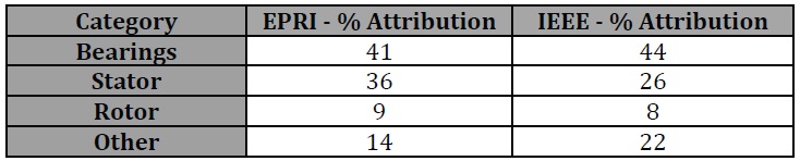 Figure 1. Motor failure cause distribution.
These numbers carry an important message. From the loathsome reality that slightly more than half of bearing failures are attributable to a lubricant or lubrication process failure (
3), shared with the reality that the motor will not operate without the bearing, we can conclude that there is a large opportunity for motor owners/operators to improve machine productivity through exercising precision lubrication for electric motors.
This article provides a plan for effective motor bearing lubrication, starting with an inventory of a typical industrial site and a reality check. The article also reviews how to identify the proper amount of grease based on nameplate details. Third, it introduces a simplified plan for lubrication that should be fully considered for many facilities. Finally, we introduce the benefit of using ultrasonic energy measurement for motor lubrication.
PROBLEM COMPLEXITY
I recently reviewed the details on 328 motors at a manufacturing site that have grease fittings and are expected to be lubricated. The motors are used as drives in a variety of machine types, including blowers, conveyors, pumps and mixers. The motors ranged from 1-100 hp. The review qualified the scope of the lubrication challenge that management at this facility faces.
The survey revealed the difficulty of applying a simple plan for lubrication based on motor horsepower or frame size. Table 1 characterizes the complexity of the combinations of motor sizes (hp ratings) and their respective bearing complements. Having multiple bearing sizes for motors of a given horsepower precludes shortcuts for estimating the volume and frequency based on horsepower.
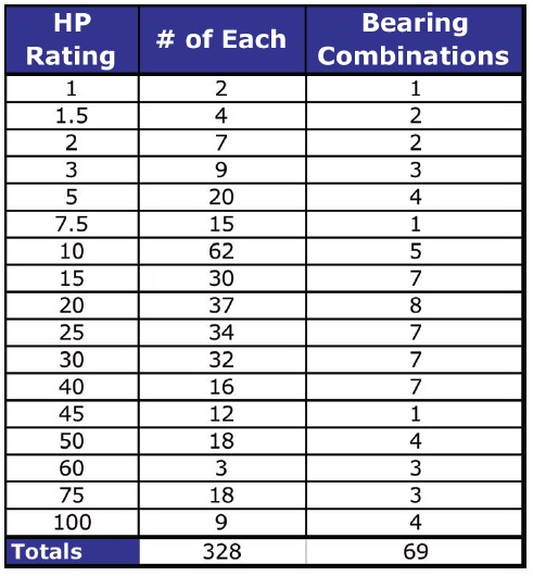 Table 1. Combinations of motor sizes (hp ratings) and their respective bearing complements.
Efforts have been made to qualify lubricant replenishment volume by NEMA (National Electrical Manufacturers Association) size, but that isn’t possible either. NEMA frame sizes are designed to depict physical dimensions needed for motor mounting and are not directly related to horsepower. It is true that as the NEMA size values increase, power ratings also increase, but a given power rating can exist in multiple motor NEMA grades.
For instance, in this group of 328 motors, there were 37 20-hp motors. There were five frame sizes represented within the group of 37 motors. Additionally, there were eight different bearing size combinations used between the five different motor frames in this group. The net effect is that each motor has to have its own motor lubrication plan. There aren’t any easy shortcuts for determining the correct volume to apply per round.
LUBRICATION REQUIREMENTS
Modern motors are equipped with the correct details on the motor nameplate that will allow the owner to determine the proper volumes. Motor manufacturers use either the Anti-Friction Bearing Manufacturers Association (AFBMA number) numbering system or the International Standards Organization (ISO) system. Both are easy to follow and, with very little effort, enable the owner to arrive at an appropriate quantity.
Figure 2 shows a motor nameplate with an AFBMA bearing number designation. The last two rows provide the bearing information. It isn’t necessarily always positioned in the last two rows, but the sequence of numbers is always similar to that shown here. The Drive End or Lower Bearing contains the number 45 BC O3 JPP3. The first two digits (45) refers to the bearing bore in millimeters. The next two digits (BC) refer to the bearing type—a Conrad Ball type bearing. The next two digits, 03, refers to the bearing series—a 6300 series bearing. With this information and the shaft speed (1,160 rpm, shown near the center) the engineer can find the exact bearing in a table and estimate both volume and frequency with a high degree of effectiveness. The non-drive end bearing is also a 6300 series Conrad Ball bearing but with a 35-millimeter bore.
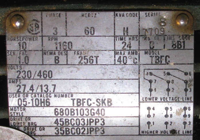 Figure 2. Motor nameplate revealing the drive end and non-drive end bearing data on an industrial motor. A full explanation of the AFBMA numbering system can be found here.
For both bearings, the last four digits pertain to seal type and arrangement. The “J” represents a pressed steel cage. The “P” represents a single shield, “PP” suggests that the bearing is double-shielded, and “3” represents a clearance designation (greater than normal clearance).
Figure 3 shows an alternate rating system that is also in broad use. This system follows the ISO bearing designation system. In this instance, the bearing data is on the right lower quadrant and is labeled BRG NO. The drive side bearing, nearly always the larger or higher quality of the two, is noted as L.S., and the non-drive side bearing is O.S. The two numbers, 6308UU and 6208UU, tell the user the bearing series, size and seal configuration.
 Figure 3. Motor nameplate using ISO bearing nomenclature.
The bearing series are denoted as 6300 and 6200, both deep grove ball bearing types. They have different widths and tolerances, with the 6300 series being slightly more capable of handling coupling end load variations from imbalance, misalignment, thrusting, etc. The last two digits of the number tell the bore dimension of the bearing when multiplied by five. In both instances, the bore is (08 X 5) 40 millimeters. “UU” designates the bearing as duplex mounted face-to-face.
Once again, armed with the details, it is possible to select an appropriate volume and frequency for replenishment. It is important to know if the bearings contain seals. EE designations for AFBMA numbers and 2RS designations for ISO numbers indicate double-sealed bearings. A double sealed bearing should not be replenished at all. Any effort to introduce grease to an EE or 2RS element has a high likelihood of collapsing the seal into the cage area and destroying the bearing.
Figure 4(a) and 4(b) illustrate the difference between a sealed and a shielded bearing. Shielded bearings have a roughly 75-micron clearance that allows for grease to be drawn into the element area by the radial movement of the balls during operation. Sealed bearings have contact between the seal and the race at the inner and outer face; consequently no grease movement is allowed.
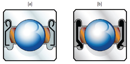 Figure 4(a) and 4(b). Shielded bearing style 4(a) is intended to be replenished; sealed bearing style 4(b) is not.
ADDING VS. PURGING
Instructions provided by a variety of interested parties over the years have suggested that grease relief line plugs should be pulled, the lines and orifice at the drain side of the housing cleared, and the bearing purged. Although still widely recognized as the textbook best practice, this approach is fraught with difficulties and potential to create more corruption than simply adding a small, pre-prescribed amount.
Figure 5 shows a typical style of bearing mounting for electric motors. The illustration to the right side of Figure 5 depicts a bearing with a shield on the inboard side (toward the windings), and the other image depicts the shield on the outboard side. The fill port, typically located at the top of the housing, is nearly always accessible, but the drain port, typically located at the bottom or side, is often obscured by covers and coupling guards and is typically not accessible.
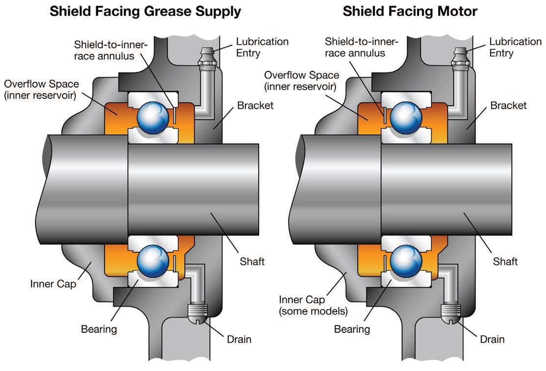 Figure 5. Typical motor element bearing, grease fill and grease relief configuration.
It is excessively laborious for the technician to secure the motor (tag and lock out), remove the guards, clear the line and supply the prescribed (engineered) amount of lubricant. Approximately 90% of the time grease does not pass through the relief port as expected. Additionally, with modern safety structures and requirements, the motor has to be lubricated while idle or have special dispensations to power up the motor (with the shielding removed) to avoid lubricating it while idle. Since the time burden is very high and the success (production of purged old grease) is very low, it appears that this long-repeated process is due for a review. There are two tangible options, as follows:
1.
Don’t lubricate low-power-rated motor bearings. During the writing of this article, several 10-hp motors were reviewed for various details, including prices. One vendor offered a high efficiency 10-hp motor for $359. A motor with this cost basis is disposable and can be purchased equipped sealed for life. The cost to schedule, execute and close a single work order for many organizations is higher than the cost of the motor. Unless the motor is operating under highly unusual considerations, low-power-rated motors should be considered for run-to-failure strategy. This approach may be viable for motors as large as 50 hp.
2.
Lubricate but don’t purge motor bearings. Assuming a motor is operating 24/7 and is lubricated on a six-month basis. One undesirable option would be to secure, uncover, clear, recover, start the motor (definitely lubricate while running, if possible), charge the housing, repeat the lock out, uncover and recover the process after 30 minutes to plug the open vent port. Instead, simply charge the motor with half of its due volume at half of its due frequency and stop.
Using the previously discussed example, the 6309 bearing has dimensions of 45-mm bore, 100-mm OD and 25-mm width. The grease volume requirement is (OD * W * .005 =) 12.5 grams per event. This volume assumes a purge of the vacant space between the races and around the elements but does not account for the lack of free space in the housing. With the “lubricated but don’t purge” approach, Six grams are introduced each three months, recognizing that the spent grease is sent toward the winding or is relieved across the gap between the motor cover face and the shaft.
There is hardly any more risk of winding corruption with this approach than with an attempted purge, and there is less risk of bearing corruption if less grease is introduced at any given moment. Additionally, the time requirement for this approach has declined from an hour to five minutes. The evident risk with this approach, perhaps no different than the previously subscribed method, is the risk that the technician will not exercise self-discipline and stop at the targeted amount.
ULTRASONIC ENERGY TOOLS
Coupled with an ultrasonic trending (UT) program, the technician could be even more selective in applying the correct volumes based on bearing condition instead of strictly calculated intervals. UT works most effectively where machines operate at medium-to-high steady state speeds. Other interferences can exist, but with a well-devised data collection method those interferences are manageable. UT signal levels rise as the lubricant in the race area dries up. If the race is dry, the energy levels are expected to be pronounced and fall nearly instantly once lubricant is reintroduced.
The high initial energy level for the dry bearing, followed by the significant drop after lubrication, is observed either audibly, visually or both during testing. The feedback enables the technician to rely on his/her senses to reinforce the discipline to apply lubricant only when needed and sparingly at that.
CONSTRUCTING A PLAN
Deep groove electric motor bearings require little grease. Most motor manufacturers offer intervals that seem unrealistic and extended well beyond typical industrial bearings, sometimes stretching to 36 months or longer. The relatively low stress to the grease from the point contact movement of the element in the race makes this feasible.
For motors operating 24/7/365 and under high load or heat stress, which are large enough to be routinely relubricated (call it 25 hp or greater), typical intervals are 6-12 months. For motors operating under excessively high load and/or temperature stress, the interval should be in the 3-6 month routine. DIN 51825, Part 2, as discussed in previous articles, delivers calculations for extended intervals. The frequencies should be calculated to establish an initial frequency rather than adopting a one-frequency fits all. However, if a one-fits-all approach is to be taken, shorter intervals are better.
Figure 6 provides volumes for common electric motor bearings in ounces and grams.
 Figure 6. Grease volume recommendations for the most common electric motor bearing sizes.
CONCLUSION
Figure 6. Grease volume recommendations for the most common electric motor bearing sizes.
CONCLUSION
Electric motor bearings shoulder a significant amount of responsibility for motor replacement, approaching 25% of total failures, and perhaps more. Motor bearing lubrication itself can but doesn’t have to be complex. Incremental placement of grease in the housing is typically conducted with an effort to purge the housing. This is rarely successful, and is exceedingly time-consuming. An alternative approach where a fraction of the requirement is supplied at an equal fraction of the interval enables appreciable improvement in time management, ease of operation and presents only slightly more risk than the existing process. In order for this approach to provide long-term success, the volumes for each motor bearing must be precisely defined.
A decision also should be reached about the value of relubricating low-power, medium-to-low criticality motors. If clear value cannot be found, then a policy should be formulated to allow low-power, medium-to-low criticality motors to operate to failure.
REFERENCES
1.
“Improved Motors for Utility Applications,” EPRI EL-4286, Vol. 1&2, 1763-1, Final Report, October 1982.
2.
Report of Large Motor Reliability Survey of Industrial and Commercial Installations, Parts I and II, Motor Reliability Working Group,
IEEE Transactions on Industry Applications, Vol. IA-21, No. 4, pp. 863-872, 1985.
3.
Antriebstechnik 18, 1979, Nr. 3, pp. 71-74.
 Mike Johnson, CLS, CMRP, MLTII, MLA1, is the principal consultant for Advanced Machine Reliability Resources, in Franklin, Tenn. You can reach him at mike.johnson@precisionlubrication.com
.