In search of a fatigue limit: A critique of ISO Standard 281:2007
Erwin V. Zaretsky, P.E. | TLT Commentary August 2010
In Part II of our debate, a leading figure in the bearings community presents his case that the new standard should be withdrawn.
KEY CONCEPTS
•
For nearly three decades many experts in the rolling bearing community have advocated the notion of a fatigue limit.
•
However, this article’s author believes data does not support the concept of a fatigue standard, which is a crucial part of the ISO 281:2007 standard.
•
The author believes this ISO 281:2007 is a mistake and should be withdrawn.
About the author
Erv Zaretsky is an engineering consultant to industry and government, noted author and lecturer, adjunct professor of engineering at Case Western Reserve University and distinguished research associate at the NASA Glenn Research Center in Cleveland, where he recently retired. He has more than 50 years of experience in mechanical engineering related to tribology, rotating machinery, fatigue and probabilistic life prediction. He has written over 200 technical papers and two books and has lectured widely throughout North America, Europe, Asia and the Middle East. He is a Fellow of both ASME and STLE and a member of two ANSI/ABMA Committees on Rolling Bearing Standards. In 1998 he was appointed to the Senior Scientific and Professional Corp., the highest rank achievable by a federal engineer or scientist. He has received four I-R 100 Awards established by the editors of R&D Magazine. In 1999 STLE presented Zaretsky with the Wilbur Deutsch Memorial Award, which honors the most outstanding paper written on the practical aspects of lubrication. He is also the recipient of numerous NASA awards for his contributions to the Space Program, among which are the NASA Medal for Exceptional Engineering Achievement, NESC Director’s Award and the Astronauts’ Silver Snoopy Award.
You can reach him at evzaretsky@gmail.com.
 Erwin V. Zaretsky
ISO Standard 281:2007 is based on a mistake. It is a disservice to the technical and industrial communities around the world. A fatigue limit should not have been included in the standard based on available data. I recommend that ISO withdraw Standard 281:2007.
WHAT’S THE PROBLEM?
ISO Standard 281: 2007 incorporates the concept of a fatigue limit within its bearing life calculation method. Furthermore, this standard assumes that the bearing is made from AISI 52100 bearing steel, is lubricated with mineral oil and has values for raceway and ball finishes that are not stated.
It is based on work first published by Stathis Ioannides and the late TedricA. Harris at the SKF Engineering and Research Centre in Nieuwegein, The Netherlands, in 1985, as well as later work published by Ioannides together with G. Bergling, and A. Gabelli, also of SKF, in 1999. The fatigue limit used in ISO Standard 281:2007 is a Von Mises stress of 900 Mpa (130,500 psi), which corresponds to a maximum Hertz contact stress of 1500 Mpa (217,500 psi). To many bearing companies and some engineers, it is the preferred method to predict ball and roller bearing lives under load and speed. However, what if a fatigue limit does not exist for high hardness alloy steels such as AISI 52100? Is a fatigue limit for through hardened bearing steels a reality or a product of imagination? Where is the data?
WHAT IS A FATIGUE LIMIT?
Before we begin our search for this fatigue limit, we should understand what it is that we are looking for so that we can recognize it.
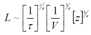
To begin, it is generally accepted that the life of a component in terms of repeated stress cycles is inversely related to a critical shearing stress, τ, to a power where
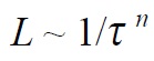
[1]
The critical shearing stress, τ, can be the orthogonal shear, maximum shear or octahedral shear stress. Some investigators have also used the Von Mises or effective stress as the decisive stress. This relation when plotted on log-log graph paper will plot as a straight line, as illustrated in Figure 1(a) and referred to as Case 1. The slope or tangent of the line is the value of the stress life exponent,
n.
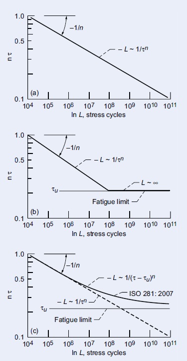 Figure 1. Stress-life (S-N) curves illustrating concept of fatigue limit. (a) Case 1, no fatigue limit. (b) Case 2, classic Wöhler curve where life is infinite below fatigue limit τu. (c) Case 3, life approaches infinity as applied stress τ approaches fatigue limit τu, as asymptote.
The classic Wöhler curve illustrated in Figure 1(b) introduces the concept of a fatigue limit where the stress-life relation is that of Equation [1] until the stress reaches the value of the fatigue limit, τ
u, at approximately 106 to 107 stress cycles, where the life is considered infinite. That is, no fatigue failures would be expected to occur. This will be referred to as Case 2.
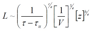
In practice, fatigue data for material types that have fatigue limits do not manifest a linear line on an log-log S-N plot but a curved line, as illustrated in Figure 1(c). This will be referred to as Case 3. The apparent relation between life, shearing stress T and fatigue limit, τ
u, is
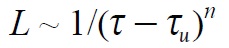
[2]
From Equation [2], for an applied stress and the presence of a fatigue limit, the resultant life will be longer than that from Equation [1] with a fatigue limit. ISO Standard 281:2007 with a fatigue limit takes the form of Case 3, Figure 1(c).
WHAT ABOUT OTHER STANDARDS?
The American Standards Institute (ANSI)/American Bearing Manufacturers Association Standards 9 and 11 are used for the load ratings and life prediction of ball and roller bearings, respectively. These standards with various updates through the years were adopted by the ABMA in 1953. ABMA change its name from the Anti-Friction Bearing Manufactures Association (AFBMA) in 1993.
ANSI/ABMA Standards 9 and 11 are based on the Lundberg-Palmgren theory published in 1947. However, this theory of Gustaf Lundberg and Arvid Palmgren dates back to 1924. At that time, Palmgren who had been working at SKF in Sweden since 1917 published a paper in Germany outlining his approach to bearing life prediction. He presented an empirical formula based on the concept of an L
10 life, or the time that 90% of a bearing population would equal or exceed without rolling-element fatigue failure. This 1924 paper by Palmgren is the first time in the literature that a probabilistic approach to life prediction of a machine element was formulated.
Assuming that a ball or roller bearing was properly designed, manufactured, installed, lubricated and maintained, rolling-element fatigue would limit the useable life of the bearing. In the life equations that Palmgren presented, he incorporated a fatigue limit or load below which no failure will occur as well as a time or location parameter before which time no failure should occur. This fatigue limit is represented by Equation [2], Case 3 of Figure 1(c).
Over the next 12 years, Palmgren evolved his bearing life prediction formulae. In 1936 Palmgren published the following:
“For a few decades after the manufacture of ball bearings had taken up on modern lines, it was generally considered that ball bearings, like other machine units, were subject to a fatigue limit, i.e., that there was a limit to their carrying capacity beyond which fatigue speedily set in but below which the bearings could continue to function for infinity.”
“Systematic examination of the results of tests made in the SKF laboratories before 1918, however, showed that no fatigue limit existed within the range covered by the comparatively heavy loads employed for test purposes. It was found that so far as the scope of the investigation was concerned, the employment of a lighter load invariably had the effect of increasing the number of revolutions a bearing could execute before fatigue set in.”
“It was certainly still assumed that a fatigue limit coexisted with a certain low specific load, but tests with light loads finally showed that the fatigue limit for infinite life, if such exists, is reached under a load lighter than all of those employed and that in practice the life is accordingly always a function of load.”
In other words, Palmgren in 1936 concluded that for bearing steels, and more specifically for AISI 52100, no fatigue limit existed as a practical matter. His conclusion is represented by the stress-life relation of Equation [1], Case 1 of Figure 1(a).
HOW DID LIFE FACTORS EMERGE?
The life equations were further empirically refined by Palmgren until 1947 when he and Lundberg published their life theory based on the Weibull distribution function and life theory. The foundation of the Lundberg-Palmgren theory and the ANSI/ABMA and later the ISO (International Organization for Standardization) Standards are based on three variables and three exponents. These are as follows:
[3]
Where
L = life; τ = critical shear stress;
V = stressed volume;
z = depth to critical shear stress;
c =shear stress-life exponent;
e = Weibull slope or modulus; and
h = exponent relating depth to the maximum shear stress to life. This formula becomes
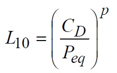
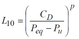
[4]
Where L
10 = life at a 90% probability of survival or a 10% probability of failure; C
D = dynamic load capacity or the theoretical load on the bearing that will result in an L
10 life of one million inner-race revolutions; P
eq radial load on the bearing and
p = load-life exponent.
Equation [4] is identical to that proposed by Palmgren in 1924. From the 1947 Lundberg-Palmgren theory, the load-life exponent,
p, equals 3 for ball bearings and 4 for roller bearings. However, Lundberg and Palmgren in 1952 proposed
p = 10/3 for roller bearings. These exponents were chosen to reflect the pre 1940 SKF bearing data.
In the late 1950s and early 1960s, the steel industry introduced vacuum-processed bearing steels. Vacuum processing resulted in bearing steels that were relatively free of hardened inclusions and resulted in significantly longer bearing lives than were achieved with air-melted (AM) steels. These vacuum-processed steels, such as AISI 52100, exhibited load-life exponents’
p of 4 for ball bearings and 5 for roller bearings, instead of 3 and 10/3, respectively used by the ANSI/ABMA and ISO Standards. This coupled with improved manufacturing techniques and lubrication technology resulted in bearing lives significantly longer than those benchmarked for the Lundberg-Palmgren equations.
In order to account for these technological achievements, I was invited by Dr. Robert L. Adamczak, chairman of the ASME Lubrication (now Tribology) Division to chair a Life Factors Committee for the ASME Lubrication Division in 1969 to codify these improvements. The committee was comprised of prominent engineers and scientists from industrial users, the bearing companies and government. The results of the committee’s work were published in September 1971 by ASME in
Life Adjustment Factors for Ball and Roller Bearings—An Engineering Design Guide.
There were five life factor categories. These categories were: Material, Processing, Lubrication, Speed and Misalignment. Nineteen sets of supporting bearing and specimen rolling element fatigue data also were published in the guide. From these data, the ASME committee concluded that, for a specific material and heat treatment, the life factors were independent of each other. The material and processing life factors were benchmarked to air-melt (AM) AISI 52100 steel.
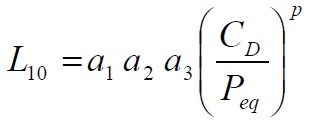
Six years after publication of the ASME design guide, the concept of life factors was adopted by ANSI, ABMA and ISO in their bearing life standards. Instead of the five life factor categories of the ASME, the standards used three. These were: a
1, Reliability; a
2, Material and Processing Properties; and a
3, Operating Conditions. The ASME categories became subcategories under Categories a
2, Material and Processing Properties; and a
3, Operating Conditions. The individual bearing company and/or user could choose the life factors they think were appropriate for their application. Equation [5] can now be written as:
[5]
In the early 1970s after the ASME publication, Eric Bamberger, Hans Signer and I, under NASA sponsorship, were the first to design and test bearings that we had manufactured from double-vacuum melted (VIM VAR) AISI M-50 at elevated temperatures. This was the first time double-vacuum melted AISI M-50 was used. We tested at speeds to 3 million DN (DN is a speed parameter, the bore of the bearing in millimeters multiplied by its speed in RPM) and temperatures of 218 C (425 F). These new test data represented approximately 150,000 bearing test hours. The bearing lives were over 100 times that predicted by the unfactored Lundberg-Palmgren equations. This bearing technology has been incorporated into most, if not all, commercial and military aircraft flying today.
Since the ASME publication, much additional bearing fatigue data have been generated. Improvements have been made in bearing manufacture, heat treatment and raceway surface finish. Better quality control techniques have been instituted by the bearing companies. There was also the introduction of hybrid bearings. Bearing rework became an acceptable procedure. As a result of these changes, it became apparent that the 1971 ASME life factors needed to be updated.
In 1985 I was invited by STLE to form a Life Factors Committee to update the life factors that were published by the ASME in 1971. A thorough search of the literature and inquiries to researchers in the field at that time revealed no data to support a fatigue limit for through-hardened bearing steels. STLE published
Life Factors for Rolling Bearings in 1992.
HOW DID A FATIGUE LIMIT RE-EMERGE?
In 1982 H.K. Lorosch of FAG Bearing Co. (now part of INASchaeffler KG) published results of fatigue tests on three groups of vacuum-degassed 7205B-size AISI 52100 inner races at maximum Hertz stresses of 2.6, 2.8 and 3.5 Gpa (370, 406 and 500 ksi), respectively. These were very highly loaded bearings. From these tests, Lorosch concluded that, “Under low loads and with elastohydrodynamic lubrication, there is no material fatigue, thus indicating that under such conditions bearing life is practically unlimited.”
O. Zwirlein and H. Schlicht, also of FAG Bearing Co., in a companion paper published concurrently in 1982 with that of Lorosch and using the same 7205B-size bearing inner races, reported large amounts of compressive residual stress due to the transformation of retained austenite into martinsite. Bearing research performed at the General Motors Research Center in Warren, Mich., in the 1950s and early 1960s showed that these compressive residual stresses can significantly increase bearing life.
My colleagues and I performed an analysis in 1965 at the NASA Lewis Research Center in Cleveland. We superimposed compressive residual stresses on the principal stresses in a ball or roller race contact. This reduced the critical shearing stress in the bearing raceway, thus increasing bearing life. As an example, a 10% reduction in the shearing stress due to the imposition of a compressive residual stress can result in a life increase of approximately 160%.
Lorosch, Zwirlein and Schlicht failed to account for the significantly large presence of these induced compressive residual stresses in their bearing raceways. Instead they assumed that the large increases in life that they reported were due to a fatigue limit. Zwirlein and Schlicht concluded that, “contact pressures (maximum Hertz stresses) less than 2.6 Gpa (370ksi) do not lead to the formation of pitting within a foreseeable period. This corresponds to ‘true endurance.’ ” However, their observation is not supported by rolling-element fatigue data in the open literature for maximum Hertz (contact) stress levels under 2.6 Gpa (370ksi). If Lorosch, Zwirlein and Schlicht were correct, no bearing in rotating machinery applications would fail by classical rolling-element fatigue since maximum Hertz stress levels in the range of 1.2 Gpa (175ksi) 10 1.9 Gpa (275ksi) are typical.
The concept of a fatigue limit made its way into the FAG bearing catalog. In the 1995 FAG Catalogue WL 41520 ED, every page that has bearing dimensional information and ratings has a statement in the upper right-hand corner, “Rolling bearings can be fail-safe if C
o/P
o is equal to or greater then 8, see page 41.” On page 41 in the section on Adjusted Rating Life the following is stated:
“Bearings are fail-safe if there is utmost cleanliness in the lubricating gap, full separation of the surfaces by the lubricating film and load corresponding to C
o/P
o greater than or equal to 8 where, C
o, is the static load capacity and, P
o, is the static load applied to the bearing.”
Based on the FAG criteria, for a ball bearing the fatigue limit occurs at a maximum Hertz stress of 2.0 Gpa (292ksi). For roller bearings, the fatigue limit occurs at a maximum Hertz stress of 1.4 Gpa (205ksi). It is difficult for me to reconcile that for the same bearing steel there are two separate fatigue limits, one for ball bearings and the other for roller bearings, that are so significantly different. It appears to me that the FAG fatigue limit is based on the classic Wöhler curve, Case 2, illustrated in Figure 1(b).
In 1985, based on the results reported by Lorosch, Zwirlein and Schlicht, Stathis Ioannides and Tedric A. Harris at the SKF Engineering and Research Centre in Nieuwegein, The Netherlands, applied Palmgren’s 1924 concept of a “fatigue limit” to the 1947 Lundberg-Palmgren equations where Equation [3] above becomes
[6]
Where, τ
u, equal the fatigue limit in shear. Ioannides and Harris do not disclose that Palmgren, also from SKF, discarded the concept of a fatigue limit in 1936. From Equation [6], Equation [4] can be rewritten to include a “fatigue-limiting” load, P
u,:
[7]
where
[8]
When P
eq ≤ P
u, bearing life is infinite and no fatigue failure would be expected. When P
u = 0, the life is the same as that for Lundberg and Palmgren. If the fatigue limit in Equation [6] or the fatigue limiting load in Equation [8] were to be eliminated, the Ioannides–Harris equations are identical to those of Lundberg and Palmgren. A comparison of Ioannides-Harris, Lundberg-Palmgren and the ANSI/ABMA Standards is shown in Figure 2.
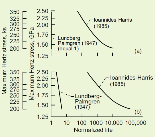 Figure 2. Comparison of life models for rolling-element bearings normalized to ANSI/ABMA standards where life L = 1. Fatigue-limiting shear stress for τ45 assumed for Ioannides-Harris model, 276 MPa (40 ksi). (a) Ball bearings. (b) Cylindrical roller bearings.
The ostensible reason Ioannides and Harris used the fatigue limit was to replace the material and processing life factors, a
2, that are used as life modifiers in conjunction with the bearing lives calculated from the Lundberg-Palmgren equations (Equation [5]). However, I have speculated that the reason it was done was to allow SKF to compete with the FAG catalog life ratings. Ioannides and Harris made the same mistake as Lorosch, Zwirlein and Schlicht; they mistook the effect of compressive residual stresses in a bearing raceway for a fatigue limit. The life equations of Ioannides and Harris were subsequently incorporated into the SKF bearing catalog.
In the online June 28, 2006 issue of “The eBearing News,” the headline reads, “ISO Adopts SKF Bearing Life Calculations.” The article goes on to say, “The International Organization for Standardization (ISO) has adopted SKF Life Theory in its upcoming update to ISO 281. The new version will replace ISO 281:1990 as modified in 2000. ISO 281:1990 itself replaced ISO 281:1977. SKF Life Theory has already been incorporated in the German standard DIN ISO 281, as of 2004. The new ISO 281 incorporates a new service life formula which, for the first time, takes into account SKFs work on fatigue limit, lubrication and contamination, all as defined by fundamental SKF Life Theory, as refined and updated.”
WHAT DOES ACTUAL BEARING DATA SHOW?
In 1995 Dr. Tedric Harris of Pennsylvania State University and professor John McCool, under contract with the U.S. Navy, analyzed 62 rolling element bearing endurance sets. These data were obtained from four bearing manufacturers, two helicopter manufacturers, three aircraft engine manufacturers and U.S. Government agency-sponsored technical reports. The data sets comprised deep-groove radial ball bearings, angular-contact ball bearings and cylindrical roller bearings for a total of 7,935 bearings. Of these, 5,321 bearings comprised one sample size for a single cylindrical roller bearing, leaving 2,614 bearings distributed among the remaining bearing types and sizes. Among the 62 rolling element bearing endurance sets, 11 had one or no failure and could not be used for the analysis. These data are summarized and plotted in Figure 3.
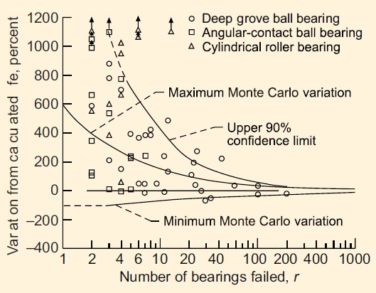 Figure 3. Variation between actual and calculated L10 bearing lives with STLE life factors for 51 sets of deep-groove and angular-contact ball bearings and cylindrical roller bearings from Harris and McCool compared with Monte Carlo variations and 90% confidence limit.
At the NASA Glenn Research Center, Brian Vlcek, Robert C. Hendricks and I randomly assembled and tested 340 virtual bearing sets totaling 31,400 radially-loaded and thrust-loaded rolling-element bearings. We determined the L
10 maximum limit and L
10 minimum limit for the number of bearings failed, r, using a Weibull-based Monte Carlo method. These limits are shown in Figure 3 together with a 90% upper confidence limit using the method of Leonard Johnson at General Motors. In Figure 3, the Harris-McCool data sets were superimposed on these plots.
Of these bearing data shown in Figure 3, 39% fall between the maximum and minimum life variations from Monte Carlo computer simulated bearing tests performed by us. Four bearing sets representing 8% of the bearing sets had lives less than that predicted. Thirty bearing sets, or 59% of the bearing sets, exceeded the maximum life variation of the Monte Carlo simulation. Eight of these bearing sets or 16% exceeded the statistical 90% confidence upper limit established by Leonard Johnson. However, only one bearing set, representing 2% of the bearing sets, fall below the lower life limit. It can be reasonably concluded that 98% of the bearing sets had acceptable life results using the Lundberg-Palmgren equations with the STLE life adjustment factors to predict bearing life.
The data of Figure 3 were broken down and replotted by Vlcek, Hendricks and I in Figure 4(a) for bearings made from CVDAISI 52100 steel. These data were adjusted for a load-life exponent p of 4 for ball bearings and 5 for roller bearings in Equation [5] and are shown in Figure 4(b). The adjusted life results (Figure 4(b)) correlated best with those of the Monte Carlo tests.
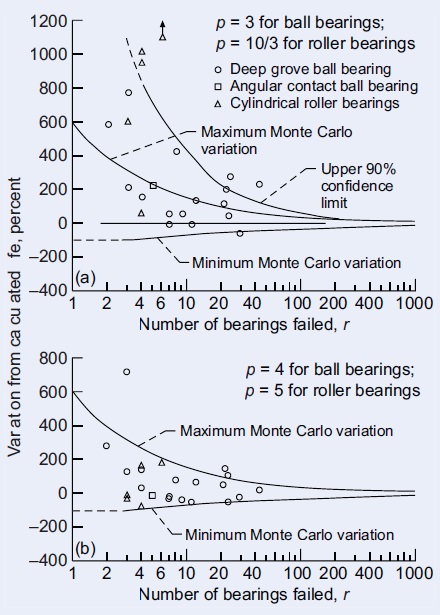 Figure 4. Effect of CVD AISI 52100 steel and load-life exponent on variation between actual and calculated L10 bearing lives with STLE life factors. (a) Load-life exponent p is 3 for ball bearings and 10/3 for cylindrical roller bearings (from Fig. 3). (b) Load-life exponent p is 4 for ball bearings and 5 for cylindrical roller bearings.
Based upon these material and processing life factors and load-life exponents, each bearing data set appears consistent with the other. These data further suggest that the load-life exponent,
p, for ball bearings in the standards should be 4 instead of 3. And for roller bearings, the load-life exponent,
p, should be 5 instead of 3.33 or 4. However, what is most important is that for these bearing sets, there was no fatigue limit manifested by the data. If a fatigue limit were to be incorporated in this data, the bearing lives would be over predicted and/or the bearings undersized for its application. These results were published in 2003 in STLE's peer-reviewed journal
Tribology Transactions.
HOW CAN I BE SO SURE?
For nearly 30 years there have been passionate advocates in the rolling bearing community for the existence of a fatigue limit. On the other hand, there have been those such as myself asking, “Where are the data to support the existence of a fatigue limit?” There are no data! However, that made no difference to those who wrote and had adopted ISO Standard 281:2007. People such as myself were considered obstructionist to technical progress. With the adoption of ISO Standard 281:2007, we were now in the position of having to prove a negative that a fatigue limit for AISI 52100 steel does not exist.
Funding to run full-scale bearing tests at low enough stress levels to prove or disprove the existence of a fatigue limit would be extremely expensive. And who would pay for it or conduct the tests? Our colleagues in Japan came up with the perfect solution.
A leader in this effort is professor Shigeo Shimizu of the School of Science and Technology at Meiji University in Kawasaki, Kanagawa, Japan. He reasoned that a material when tested should only react to its state of stress and environment. In other words, if AISI 52100 steel had a fatigue limit, a stress below which no failure will occur, it should exhibit this limit no matter what type of fatigue test was performed. A statistically significant number of fatigue tests are required over a range of shearing stresses to assure with reasonable engineering and scientific certainty that the steel either did or did not exhibit a fatigue limit. And, if a fatigue limit did exist, what is its value?
In 2008 Shimizu and his colleagues, professors K. Tosha, D. Ueda and H. Shimoda, published a journal paper in
Tribology Transactions reporting the results of rotating beam fatigue experiments for through-hardened AISI 52100 steel at very low shearing stresses as low as 0.48 GPA (69.6ksi). “The test results produced fatigue lives in excess of 100 million stress cycles without the manifestation of a fatigue limit.”
In order to assure the credibility of his work, additional research was conducted and published by Shimizu together with his colleagues, professors K. Tsuchiya and K. Tosha, in a 2009 issue of
Tribology Transactions. They tested six groups of AISI 52100 bearing steel specimens using four-alternating torsion fatigue life test rigs to determine whether a fatigue limit exists or not and to compare the resultant shear stress-life relation with that used for rolling-element bearing life prediction.
The number of specimens in each sample size ranged from 19 to 33 specimens for a total of 150 tests. The tests were run at 0.5, 0.63, 0.76, 0.80, 0.95 and 1.00 Gpa (75.5, 91.4, 110.2, 116. 0, 137.8 and 145ksi) maximum shearing stress amplitudes. The stress-life curves of these data, as shown in Figure 5, show an inverse dependence of life on the shearing stress as in Case 1, Figure 1(a), but do not show an inverse relation on the difference of the shearing stress minus a fatigue limiting stress as in Case 3, Figure 1(c). The shear stress-life exponent, n, for the AISI 52100 steel was 10.34 from the three-parameter Weibull analysis and was independent of the Weibull slope,
e.
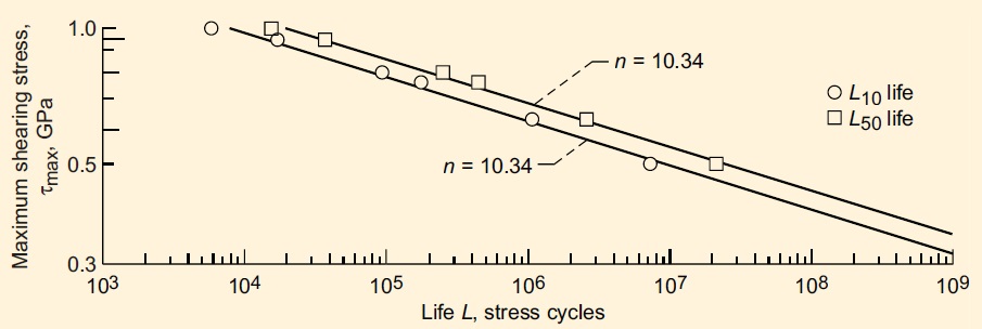 Figure 5. Probabilistic stress-life (P-S-N) curves for AISI 52100 bearing steel in reverse torsional stress. From three-parameter Weibull analysis of Shigeo Shimizu, Kazuo Tsuchiya and Katsuji Tosha.
In 2007 Dr. T. Sakai discussed experimental results obtained by the Research Group for Material Strength in Japan. He presented stress-life rotating bending fatigue data from six different laboratories in Japan for AISI 52100 bearing steel. He also presented stress-life fatigue data for axial loading. The resultant lives were in excess of a billion (10
9) stress cycles at maximum shearing stresses (τ
max) as low as 0.35 Gpa (50.8 ksi) without an apparent fatigue limit.
It can be reasonably concluded from the volumes of data from Meiji University and Dr. Sakai that the fatigue stress-life relation that incorporates a fatigue limit for AISI 52100 steel as in ISO Standard 281:2007 is incorrect. These data preclude the existence of a fatigue limit to maximum shearing stresses (τ
max) as low as 0.35 Gpa (50.8 ksi). This is equivalent to a maximum Hertz stress for ball bearings of 1.09 Gpa (158.1 ksi) and 1.17 Gpa (169.7 ksi) for roller bearings.
Arvid Palmgren got it right 74 years ago!
FOR FURTHER READING:
1.
Bamberger, E.N., Harris, T.A., Kacmarsky, W.M., Moyer, C. A., Parker, R.J., Sherlock, J.J. and Zaretsky, E.V. (1971),
Life Adjustment Factors for Ball and Roller Bearings–An Engineering Design Guide, ASME, New York.
2.
Bamberger, E.N., Zaretsky, E.V. and Signer, H. (1976), “Endurance and Failure Characteristics of Main-Shaft Jet Engine Bearing at 3×10
6 DN,”
Journal of Lubrication Technology,
98(4), pp. 580–585.
3.
Harris, T.A. (1995), “Final Report Establishment of a New Rolling Bearing Contact Life Calculation Method,” U.S. Naval Air Warfare Center, Aircraft Division Trenton, Contact No.
N68335–93–C–0111.
4.
Harris, T.A. and McCool, J.J. (1996), “On the Accuracy of Rolling Bearing Fatigue Life Prediction,”
ASME Journal of Tribology,
118 (2), pp. 297–310.
5.
Ioannides, E. and Harris, T.A. (1985), “New Fatigue Life Model for Rolling Bearings,” ASME J.
Tribol. Trans., 107 (3), pp. 367–378.
6.
Ioannides, E., Bergling, G. and Gabelli, A. (1999), “An Analytical Formulation for the Life of Rolling Bearings,”
Acta Polytechnica Scandinavica, Mechanical Engineering Series,
137, Finland.
7.
ISO 281:2007: “Rolling Bearings-Dynamic Load Ratings and Rating Life,” International Organization for Standardization, Geneva, 2007.
8.
Lundberg, G. and Palmgren, A. (1947), “Dynamic Capacity of Rolling Bearings,”
Acta Polytechnica, Mechanical Engineering Series,
1 (3), Stockholm, Sweden.
9.
Lundberg, G. and Palmgren, A. (1952), “Dynamic Capacity of Roller Bearings,”
Acta Polytechnica, Mechanical Engineering Series,
2 (4), Stockholm, Sweden.
10.
Lorosch, H.K. (1982), “Influence of Load on the Magnitude of the Life Exponent for Rolling Bearings,”
Rolling Contact Fatigue Testing of Bearing Steels, J.J.C. Hoo, ed., ASTM STP-
771, American Society for Testing and Materials, Philadelphia, Pa., pp. 275–292.
11.
Palmgren, A. (1924), “Die Lebansdauer von Kugellagern (The Service Life of Ball Bearings),”
Zeitschrift des Vereines Deutscher Ingenieure,
68 (14), pp. 339–341, (NASA TT-F-13460, 1971).
12.
Palmgren, A. (1936), “Om Kullager Barformaga Och Livslangd,” (On the Carrying Capacity and Life of Ball Bearings), Teknisk Tidskrift, Mek, h. 2, (in Swedish) and
The Ball Bearing Journal,
3, 1937, pp. 34-44.
13.
Parker, R.J., Zaretsky, E.V. and Bamberger, E.N. (1974), “Evaluation of Load-Life Relation With Ball Bearings at 500° F,”
Journal of Lubrication Technology,
96 (3), pp. 391–397.
14.
Saki, T., Takeda, M., Shiozawa, K., Ochi, Y., Nakajima, M., Nakamura, T. and Oguma, Y. (2000), “Experimental Reconfiguration of Characteristic S-N Property for High Carbon Chromium Bearing Steel in Wide Life Region in Rotating Bending,”
J. Soc. Mat. Sci., Japan,
49 (7), pp. 779-785 (in Japanese).
15.
Saki, T. (2007), “Review and Prospects for Current Studies on Very High Cycle Fatigue of Metallic Materials for Machine Structure Use,” Proc. 4th International Conference on Very High Cycle Fatigue (VHCF-4), TMS (The Minerals, Metals and Materials Society), pp. 3-12.
16.
Shimizu, S., Tsuchiya, K. and Tosha, K. (2009), “Probabilistic Stress-Life (P-S-N) Study on Bearing Steel Using Alternating Torsion Life Test,”
Tribology Transactions,
52 (6), pp. 807–816.
17.
The eBearing News, “ISO Adopts SKF Bearing Life Calculations,” click
here, June 28, 2006.
18.
Tosha, K., Ueda, D., Shimoda, H. and Shimizu, S. (2008), “A Study on P-S-N Curve for Rotating Bending Fatigue Test for Bearing Steel,”
Tribology Transactions,
51 (2), pp. 166-172.
19.
Vlcek, B.L., Hendricks, R.C. and Zaretsky, E.V. (2003), “Determination of Rolling-Element Fatigue Life from Computer Generated Bearing Tests,”
Tribology Transactions,
46(3), pp. 479–493.
20.
Zaretsky, E.V. (1992),
Life Factors for Rolling Bearings, STLE SP-34, Society of Tribologists and Lubrication Engineers, Park Ridge, Ill.
21.
Zaretsky, E.V., Poplawski, J.V. and Peters, S.M. (1996), “Comparison of Life Theories for Rolling-Element Bearings,”
Tribology Transactions,
39 (2), pp. 237–248.
22.
Zaretsky, E.V. (1997),
Tribology for Aerospace Applications, STLE SP-37, Society of Tribologists and Lubrication Engineers, Park Ridge, Ill.
23.
Zaretsky. E.V. (1998), “A Palmgren Revisited—A Basis for Bearing Life Prediction,”
Lubrication Engineering,
54 (2), pp. 18–24.
24.
Zaretsky, E.V., Poplawski, J.V. and Miller, C.R., “Rolling Bearing Life Prediction—Past, Present, and Future,” in Proc. Of the International Tribology Conf. Nagasaki, 2000, 1, Japanese Society of Tribologists, Tokyo, Japan, 2001, pp. 101–107.
25.
Zaretsky, E.V. (2010), “Rolling Bearing Life Prediction, Theory and Application,”
Recent Developments in Wear, Prevention, Friction and Lubrication, G ed. George K. Nikas, Research Signpost, Kerala, India.
26.
Zwirlein, O. and Schlicht, H. (1982), “Rolling Contact Fatigue Testing of Bearing Steels, J.J.C. Hoo, ed., ASTM STP-771, American Society for Testing and Materials, Philadelphia, Pa., pp. 358–379.