ISO 281:2007 bearing-life standard—and the answer is?
TLT Cover Story July 2010
Every major industrialized nation in the world accepts the new bearing-life standard except the U.S. Why—and what does it mean for the industry?
KEY CONCEPTS
•
TLT interviewed three men who were involved with the development of the new ISO bearing standard.
•
There is not yet complete agreement or full acceptance of the new standard in the U.S.
•
However, the standard has been accepted by both the federal government and industries where the bearing environment is carefully controlled, including aerospace, compressors and automobile hub units.
Waiting for the official appearance of any new ISO standard is like waiting for a glacier to calve, only slower. An acclaimed technological breakthrough may wind through the dark halls of science and industry for 10-20 years before emerging into the light of international acceptance because standards must represent an accessible and agreed-upon baseline for everyone, not just the esoteric capabilities of industry leaders.
Yet even against this backdrop, the story of ISO 281:2007, “Rolling bearings—Dynamic load ratings and rating life,” is remarkable for the mix of science and opinion that now leaves U.S. bearing users living with standards from the time when the Cold War ended and The Simpsons first appeared on Fox TV.
To throw light on this story, TLT interviewed three men who were involved with the development of the new standard: STLE-member Myron McKenzie, chief engineer of the American Roller Bearing Co. In Morganton, N.C. (who suggested this article); Martin Correns, director of advanced engineering analysis and simulation for INA-Schaeffler KG in Herzogenaurach, Germany; and STLE life-member Dan Snyder, recently retired as director of application engineering for SKF in Lansdale, Pa., and now an industry consultant active in the Bearing Technical Committee of the American Bearing Manufacturers Association (ABMA).
We’ll recap a history of bearing life calculations, review the startlingly new approach that Stathis Ioannides and STLE life-member Ted Harris introduced in 1985, describe how that approach evolved into ISO 281:2007 and investigate how the U.S. ABMA has so far not adopted it.
THE FATHERS STILL LIVE
“The 1947 Lundberg and Palmgren report on ‘Dynamic Capacity of Rolling Bearings’ is still the basis for all the bearing life calculations that are done today,” says McKenzie. “They are the fathers of modern bearing life calculations. Before their report, every bearing manufacturer calculated life in its own way.” The bearing industry needed a unified method for calculating bearing life.
At the end of World War II, bearings were crude chunks of steel by today’s standards, and the Lundberg and Palmgren report, which was based on thousands of SKF experiments, reflected that. “Materials then were full of voids and inclusions like slag,” McKenzie says. “This would create a stress concentration inside the material. A roller going by would start an internal crack that would work its way up to the surface and cause a spall.”
The 1947 Lundberg-Palmgren equation includes the probability of survival, the internal stress created by the external load, the number of stress repetitions, the stressed volume, the contact area and the length of the raceway. In 1952, the two men expanded their vision to produce the formula that remains at the heart of all of today’s standards:
L
10 = (C/F)
P
L
10 = bearing life, the point at which 10% of the bearings will fail
C = basic dynamic capacity of the bearing based on the number of rolling elements, the roller length and diameter, and the contact angle
F = applied load
P = a power: 3 for ball bearings, 4 for pure line-contact bearings, or 10/3 for typical roller bearings.
Ten years later, in 1962, ISO adopted this approach in their Recommendation R281. With a methodology that could easily be used by both bearing manufacturers and users, R281 was a leap forward—but only the beginning of the story.
FACTORS IN BEARING LIFE
As bearings improved, engineers started to recognize that many factors besides slag inclusions and voids could affect bearing life, and in 1971 ASME published a design guide on “Life Adjustment Factors.” Here the L
10 from Lundberg-Palmgren was multiplied by five separate and independent factors for material, processing, lubrication, speed and misalignment. Note the word “independent.”
ISO took this work and launched its own ISO 281 standard in 1978 using three independent life factors:
L
na = (a
1)(a
2)(a
3)L
10
a
1 = Reliability: this factor converts L
10 to L
whatever (e.g., for L
1 or 99% reliability, a
1 = 0.21)
a
2 = Bearing properties: this factor reflects use of special steel, coatings, etc., and is left up to the discretion of the manufacturer
a
3 = Operating conditions: reflects lubrication, contamination, temperature, mounting conditions, misalignment, etc.
It is perhaps not surprising that this industry-derived standard merged the ASME’s five factors to create something bearing manufacturers could manipulate more easily; regardless, the standard maintains the idea of independent factors.
McKenzie notes that caution is in order: “In the standard, you multiply these three factors together to calculate the bearing life,” he says. “Now a
1 is rightfully independent, but a
2 and a
3 may or may not be independent. If you know that you’ll have a thin oil film, you might try to compensate by using a special material or a special coating, but that may not work, and the equation may not predict the life you’ll get in the field. The consumer should consult the bearing manufacturer when using this kind of factoring method.”
In the late ’70s, ISO life predictions matched bearing performance well enough for users to avoid warranty problems. But as manufacturers began designing for more demanding bearing applications, actual life began to diverge from predictions. Steel quality, better designs, more accurate production methods and improved surface finishes all played a role.
McKenzie published a paper that showed the progression of test lives, over time, of a Fafnir/Torrington 35-mm ball bearing. By 1984, bearing life was four times better than ISO predictions; by the late ’80s, it was six times better; and by 1994 nearly 14 times better. (
See Figure 1 showing McKenzie’s Fafnir/Torrington test results for 35-mm ball bearings.) “I’ve seen circumstances where the actual life can be a hundred times the ISO life due to new coatings, materials or processing,” McKenzie says.
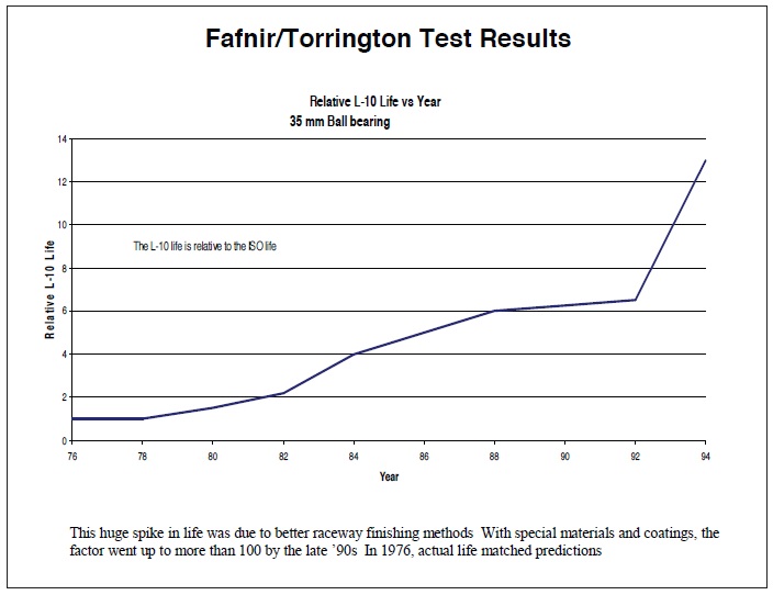 Figure 1. Fafnir/Torrington test results for 35-mm ball bearings (Courtesy of Myron McKenzie,
American Roller Bearing Co.)
Clearly, bearing life reality was no longer holding hands with the dated ISO 281:1978. What now?
INDEPENDENCE, INTERDEPENDENCE
As early as 1925, Palmgren had considered the interdependence of bearing life factors and even published a paper about it, although these ideas were not implemented in the Lundberg-Palmgren calculations. But as manufacturers collected data and tried to improve their bearing life predictions, some of them also noted that factors a
2 and a
3 seemed to be interdependent rather than independent. Many manufacturers created new combinations, which they expressed as a
23. Researchers at FAG were particularly active in these investigations and the first to observe what they called “fatigue limit.”
Everyone knows that if you bend a paper clip back and forth enough times, it breaks: fatigue. But if you bend it only a little, it lasts forever. Common sense. Yet no one had ever applied this particular common sense notion to bearings, and the idea that it
did apply was a big deal: If you could minimize stress below a certain point—with adequate lubrication, no contamination and a load well within the bearing’s dynamic capacity—the bearing, like the paper clip, could last forever!
Stathis Ioannides and Ted Harris at SKF ran with this idea, confirmed the FAG results, and in 1985, 25 years ago, wrote a pivotal paper titled “A New Fatigue Life Model for Rolling Bearings.” Their methodology built on previous work but accounted for current technology and data. Forget about independent life adjustment factors, they said.
The important thing is the difference between the actual stress within the bearing and the fatigue stress limit for each location within the material. Life factors are not independent but interdependent, and all factors affect the fatigue life. The only two key factors are the stress on the bearing and the fatigue stress limit—the strength—of the material. Ioannides and Harris kept the Lundberg and Palmgren equation but replaced “stress” with the difference between stress and the fatigue stress limit. And in place of stress volume, they introduced “finite volume of stress” based on finite element analysis.
“In the ’60s and ’70s, we used to do bearing calculations by hand” says Dan Snyder, recently retired from SKF where he was heavily involved with user bearing applications. “It wasn’t until the ’80s and ’90s that we had computers to do the things we could never do before. In the ’90s we could look at finite elements within the bearing—look at the stress on each element, compare it with stress fatigue limit of each element, and then combine everything to determine the lifetime of the bearing. That’s what the Ioannides-Harris method proposed.”
“The idea that bearing steel has a fatigue stress limit is pretty revolutionary,” McKenzie says. Palmgren said that no bearing gives an unlimited length of service. “There are several well-respected researchers in the rolling element bearing community who remain opposed to the idea of a fatigue stress limit.”
One of those people—and one of the most well-respected members of the bearing-life community—is STLE life-member Erwin Zaretsky, recently retired from the NASA Glenn Research Center in Cleveland where he was chief engineer for materials and structures. “At least for me,” McKenzie says, “if Erv Zaretsky throws up a warning flag I take notice and try my best to understand his reasoning. He has earned that respect from all of us.”
DIVERGING PATHS
Seven years after the introduction of the Ioannides-Harris fatigue-life model, Zaretsky led publication of
Life Factors for Rolling Bearings (published by STLE), an expanded version of what ASME had proposed in 1972 but containing about 30 new life adjustment factors. “I was one of 14 people that contributed to this book,” McKenzie says. “The STLE book was an advancement over the ASME design guide. I am very proud to have contributed to it. The beauty of a factor-based approach is that it is easy to see which factors have the greatest influence on bearing life. The concern that many on the ISO 281 committee had with the factor-based approach is not considering the interdependence of factors. This can lead to a poor prediction of bearing life.”
Zaretsky continued to focus on life adjustment factors and objected to use of a fatigue stress limit. Meanwhile, the ISO shifted its focus to the Ioannides-Harris model. The result was ISO 281, Amendment 2:2000, a framework methodology that replaced a
2 and a
3 (and a
23) with a single integrated “a
xyz.”
“The problem then was that no one had determined how to calculate a
xyz,” Snyder says. “It was left up to the bearing manufacturers. So we had an a
SKF, an a
TIM, an a
FAG, and so on. Everyone had their own factor.”
While manufacturers struggled with ways to use the new ISO standard, Ted Harris (co-author of the seminal paper) led an effort within the ASME to update its 1971 design guide. Bearing manufacturers met. End-users met. Papers and presentations piled up. ASME introduced its program in 2005, much of which ultimately found its way into a new ISO standard.
Meanwhile, perhaps the most significant activity was taking place within the DIN standards group in Germany.
FROM ISO 281:2000 TO ISO 281:2007
“The ISO 281:2000 standard was designed to be done on a piece of paper with a pocket calculator,” says Martin Correns, who headed the working group in developing a new DIN standard for Germany. “Three manufacturers calculated the same bearing for the same application using the ISO 281:2000 approach and came up with lifetimes that ranged from 6,500 to 34,000 hours!” he says. “The 2000 standard did not reflect the sophisticated calculation software that the industry uses nowadays (
see Figure 2).”
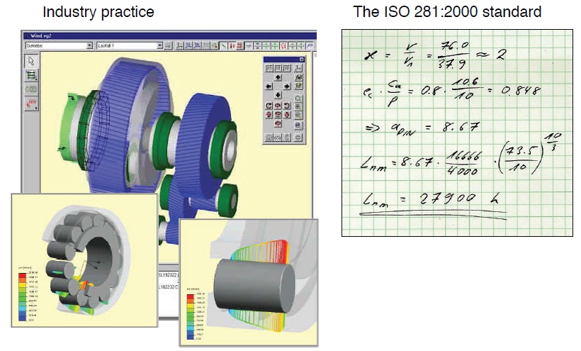 Figure 2. The ISO 281:2000 standard (shown on the right) took a new approach to bearing life, but left it as a simple pocket—calculator formula—nowhere close to industry practice (shown on the left). (Courtesy of Schaeffler)
“We realized we could not standardize the calculation software,” Correns continues, “but we could standardize the underlying concept, and that is what we have done.” The DIN standard was published in Germany in 2003, and also became part of ISO 281:2007 and ISO Technical Specification, ISO/TS 16281.
The integrated life adjustment factor in the new ISO 281:2007 is now called aISO and includes four interdependent factors: lubrication, contamination, load and the fatigue stress limit of the bearing material.
Lubrication regime is quantified by the parameter kappa, κ, widely used in Europe since the 1980s. Kappa is the ratio of the actual viscosity of the lubricant in the bearing to a “reference viscosity.” The reference viscosity is that which would produce a lubricant film thickness equal to the composite surface roughness of the rolling element and the raceway—it is also the viscosity that will give you a lambda (λ) value = 1, where lambda is the oil film thickness divided by the composite surface roughness. If κ =1, you have a lubrication regime where the surface asperities of the roller and the raceway just touch. Any lube regime where κ ≥ 1 is a good one, and lubrication improves as κ increases.
The key thing in determining κ is computing the reference viscosity, and that is mind-numbingly long and complex. In ISO 281:2007 it has been condensed to a simplified equation that depends only on pitch diameter and speed. There is also a graph (
see Figure 3). Unlike the lubrication term λ, widely used in the U.S. and Japan, κ does not require knowledge of actual surface roughness—a good thing since bearing manufacturers consider this information confidential and don’t make it available to end-users.
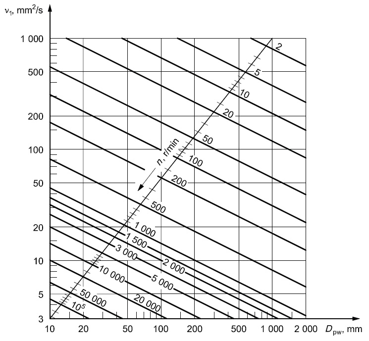 Figure 3.
 The reference viscosity (on the y-axis) can be determined from the pitch diameter (the x-axis) and the speed of the bearing (the diagonal lines). The lubrication factor, Kappa, is the ratio of actual viscosity to reference viscosity. (
Courtesy of Schaeffler)
Kappa, of course, is not independent; for example, high speeds will sling lubricant away from the contact area in much the same way that automobile tires speeding down a wet road push water out of their tracks. Heavy load also impacts lubricant performance.
Contamination is quantified by factor e
c, (
see Figure 4). Somewhat simplified, e
c is the inverse of stress concentration: it is the ratio of the maximum internal stress in a clean contact to the stress in a contaminated contact. The higher the e
c value, the cleaner the contact.
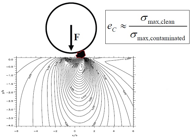 Figure 4. The contamination factor is the inverse of the stress concentration in the material. A higher factor equates to cleaner operating conditions. (Courtesy of Schaeffler)
Contaminant particles create stress, and they also create pits with rims, something like the impact craters on the moon. When a following roller passes over the rim, it creates additional stress in the underlying material (
see Figure 5). If contaminant particles are small enough or the material hard enough to prevent pits, the contamination effect is slight—but once pits start happening, bearing life nosedives.
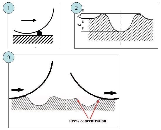 Figure 5. A particle creates a pit and pit-edge proportional to its size. Rollers following behind generate stress when they contact the rims of the pit. (Courtesy of Schaeffler)
Contaminants, too, have interdependencies: higher material yield strength and/or better lubrication reduces contact and pit size, and larger rollers are less affected by pits. “It’s like riding a bicycle over a pothole,” says Correns. “The larger the wheel, the smoother the ride.” ISO/TS 16281 contains detailed graphs and tables for determining (or estimating) e
c based on pitch and general conditions.
Fatigue stress limit is given by C
u, the load where the fatigue limit of the bearing material is just reached. C
u is calculated for ideal conditions using the simplified or advanced formulas in ISO 281 Annex B. In practical terms, C
u is the load that produces a contact stress between the roller or ball and raceway of 1,500 MPa.
The final life adjustment factor a
ISO is given by the following equation and shown on the y-axis of Figure 6. It is a function of the lubrication factor κ (the curved lines in the graph) and (e
c-C
u)/P, were e
c is contamination, C
u is fatigue stress limit, and P is the dynamic equivalent load, what was called “F” in the original Lundberg-Palmgren term, (C/F)
P.
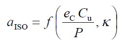
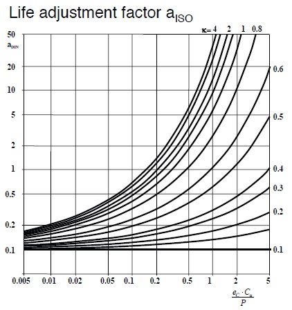 Figure 6. The life adjustment factor is on the y-axis; the curved lines represent different values for the lubrication factor, Kappa; and the x-axis is the difference between the contamination factor and the fatigue stress limit divided by the load. (Courtesy of Schaeffler)
“There is no such thing as a life factor that is solely dependent on just one parameter,” Correns says. “In the end, bearing life is a function of cyclic stress vs. the strength of the material. All parameters that affect bearing life will change either stress concentration or material strength.”
“The ISO/TS 16281 gives all the necessary equations to calculate the internal load distribution in the bearing, the contact stresses and a reference rating life based on this unified approach,” Correns continues. “For the first time, a customer can directly compare the results of different advanced calculation programs. This approach has been very successful in the field—for example, it is now mandatory to use this method for the certification of wind turbine gearboxes.”
PROOF OF INTERDEPENDENCE
It’s all very well to offer common-sense arguments for the interdependence of life adjustment factors, but what about some form of mathematical proof? Figure 7 shows the pivotal Correns diagram that helped persuade the German DIN organization.
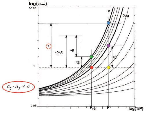 Figure 7. This graph shows the interdependence of load (P, on the x-axis) and lubrication (the Kappa curves) on the life adjustment factor (a, the y-axis). Changing both load and lube—moving from the red point to the blue point—changes “a” by a total amount that is not equal to the product of the two separate adjustments. (Courtesy of Schaeffler)
This graph is similar to Figure 6, except that the y-axis, a
ISO, is a log scale, and contamination and fatigue stress have been removed so that the x-axis reflects only the inverse of load. Two κ lines have been highlighted: the lower line for a reference κ, and the upper for conditions with better lubrication.
Now conduct three mental experiments with this graph:
Reduce load, keep lubrication the same: Start at the red point on the reference κ line, decrease the load by moving to the yellow point; then move to the purple point to keep lubrication the same. The life adjustment factor increases by amount ‘a
5.’
Improve lubrication, keep load the same: Start at the red point and improve lubrication by moving to the green point, without changing the load. The life adjustment factor increases by amount ‘a
2.’
Reduce load and improve lubrication: Now move from the red point to the blue point. The life adjustment factor changes by amount ‘a’ (in the red circle). Note that life adjustment factor for the sum of both changes is not equal to the sum of the two separate adjustments.
“The point is,” says Correns, “You can’t use independent life factors, because they don’t work out! Whatever you change, you will change all the separate life factors. The only way to approach it is with a single unified factor that takes everything into account. It all comes down to cyclic stress and material hardness.”
ISO 281 AND THE U.S.A
While Germany (DIN) and the rest of the world have adopted ISO 281:2007, the U.S.A (ANSI) through the ABMA’s standards approving advisory groups has not—even though the new standard appears to produce much more relevant results. Myron McKenzie has an example showing the disparity when calculating bearing life for the same bearing in two locations:
Location 1: The bearing is subjected to typical contamination conditions: it has no integral seals, the oil is only coarsely filtered, and contaminants can enter from the surroundings. The operating viscosity = 9 mm
2/s.
Location 2: The bearing is very clean, and all oil is filtered through an extremely fine filter. However, the operating viscosity = 6 mm
2/s, one-third lower than Location 1.
The result? According to ISO 281:2007, bearing life at Location 1 will be 36% lower than what is predicted by the U.S. ABMA standard, even though the lubrication regime is better. Meanwhile, bearing life at Location 2 will be 20% greater than what the ABMA standard predicts—because the bearing is so much cleaner. Thus it appears that the new standard will offer bearing manufacturers and end-users a way to evaluate exactly what conditions and investments will offer the best return on their investment.
So, where does all this leave the United States?
“We have a Standard 11 for roller bearings and a Standard 9 for ball bearings in this country, and they have not been revised since 1992,” says Dan Snyder, who is active in the ABMA technical committee responsible for maintaining and developing U.S. standards. “When the ISO standard was first adopted in 2000, the U.S. decided not to adopt it because there was no calculation method. When the new ISO 281:2007 came out, Myron McKenzie and I were part of the working group trying to get it adopted here. But there is still a group of people—Zaretsky is the most well-known but certainly not the only one—who do not accept the existence of the fatigue stress limit or the interdependence of the life adjustment factors. We have to arrive at a consensus of what to accept and not accept, and it takes time to work through it.”
Snyder notes that regardless of official standards, virtually all U.S. bearing manufacturers have embraced ISO 281:2007 and are using it to design bearings and develop stress profiles. “The standard has led to more sealed-for-life bearings,” he says, “and it’s also impacting the manufacturing environment. The industry is producing a much better bearing because they now have a better understanding of how environmental conditions influence bearing life, and they’ve modified their designs and machining.”
Yet bearing end-users remain confused by the new standard and reluctant to adopt something without the ABMA seal of approval. “Years ago all major companies had their own bearing experts and did a lot of their own test work,” Snyder says, “but now a lot of the responsibility for test work has been pushed back on the suppliers. It used to be that GM and other big companies did their own transmission and engine design, but now they just tell the manufacturers the performance they need, buy the parts and assemble them. So the end-users remain comfortable with the old standards—they pick a safety factor based on their old rules of thumb, and if something doesn’t work, they consider it the supplier’s fault—either poor quality or bad design. ISO 281:2007 throws a monkey wrench in that.”
According to Snyder, only customers that have had problems are eager to adopt the new standards, because they see it as a solution. “If I walk into a customer that doesn’t have a field problem and say, ‘If you put a smaller filter in and use a bearing with seals, I can increase your bearing life by a factor of 10, and you can extend your warranty and improve efficiency…’ the customer thinks it’s some marketing gimmick. Because at the end of the day, they’re the ones taking the risk by accepting the change.”
“American industries generally tend to be conservative,” Snyder concludes. “We don’t change much, which is why we have old steel mills and old paper mills. We have the most advanced technology, but we export it! If I suggest something, people ask who else is using it. No one wants to be the first.”
Of course, this is not the complete picture. The Navy and Air Force (but not NASA) have both accepted ISO 281:2007, as have industries in which the bearing environment is carefully controlled and monitored: aerospace, compressors and automobile hub units. Certification requirements for insurance are also driving factors; wind turbines provide a prime example where ISO 281:2007 must be followed. Snyder reports that the AGMA group developing a standard for wind turbine gearboxes is embracing ISO 281:2007. “It’s progress,” he says.
What has to happen next? “An American standard is supposed to cut across government, manufacturers, users, suppliers, everyone,” Snyder says. “So ANSI (the official U. S. member of the ISO) is very specific about getting input from everyone. Within ANSI, the AGMA supports the standard, and the technical committee of bearing manufacturers within the ABMA supports it. But some bearing end-users and others who are not privileged to see the background test work do not.
“The more people become aware of the standard and use it in every day work, the more they’ll understand the potential it offers,” Snyder says. “It doesn’t make any sense at all for the U.S. to have a separate standard from the rest of the world. We are competing on a global basis. If we want refinements to ISO standards, we should advance our concerns in the ISO development working groups instead of having our own ANSI standard.”
“The ISO 281:2007 standard is based on data and calculation procedures that were presented to the committee,” says Myron McKenzie. This standard will continue to evolve over time. As more information becomes available, refinements will be made to the standard. Even the concept of fatigue stress limit could go away if data showed that it really doesn’t exist. Lundberg and Palmgren are to my way of thinking the fathers of modern bearing life calculations,” says McKenzie. “Our generation has Ioannides, Harris and Zaretsky, among many others, that have contributed to bettering our understanding of how bearings operate and ultimately fail.”
Stathis Ioannides himself says, “The standard has been developed over many years, based on a large body of data and published work. The current ISO is based on modern bearing tests, i.e., bearings that are used in the industry today. Modern bearings incorporate many improvements (e.g., manufacturing, material, design) compared to the bearings tested by government bodies like NASA in the ’70s, and consequently they have improved life performance. The calculation methods in the new ISO have been updated to keep up with these real performance improvements. The world standard has been adopted after extensive scrutiny over many years by experts from many countries, and it should be changed only through systematic evidence of further improved predictions after similar scrutiny.”
FOR FUTHER READING:
Harris, T.A. and Kotzalas, M.N. (2007), “
Rolling Bearing Analysis, Fifth Edition,” CRC Press.
Ioannides, E., Bergling, G. and Gabelli, A. (1999), “An Analytical Formulation for the Life of Rolling Bearings,” Acta Polytechnica Scandinavica Mechanical Engineering Series, 137.
ISO 281:2007: “Rolling Bearings—Dynamic Load Ratings and Rating Life.”
Ioannides, E. and Harris, T.A. (1985), “A New Fatigue Life Model for Rolling Bearings,”
ASME Journal of Tribology,
107, pp. 367-378.
Harris, T.A. and Yu, W.-K. (1999), “Lundberg-Palmgren Fatigue Theory: Considerations of Failure Stress and Stressed Volume,”
ASME Journal of Tribology,
121 (1), pp. 85-89.
95-TRIB-58: “Load and Life Ratings for Modern Ball and Roller Bearings,” Presented at the 1995 STLE/ASME Tribology Conference Covering the Life Prediction Capability of the ISO and ANS Standards and Recommendations for Improvement, Oct. 8-11, 1995, Orlando Fla.
96-TRIB-67: “Load and Life Ratings for Modern Ball and Roller Bearings,” A collection of papers presented at the 1996 STLE/ASME International Tribology Conference Bearing Users Experiences and Requirements for Improved Life Prediction Capability Beyond Current ISO and ANSI Standards, Oct. 13-18, 1996, San Francisco, Calif.
98-TRIB-57: “Life Ratings for Modern Rolling Bearings,” (ASME Tribology Division Technical Committee —Bearings Suppliers and Customers), Presented at the 1998 STLE/ASME Joint Tribology Conference, Oct. 25-29, 1998, Toronto, Ontario, Canada.