Strategic oil analysis: Onsite practices using sensory inspection
Mike Johnson | TLT Best Practices April 2010
By using our human senses, we can learn much about the condition of the oil—and the machine.

KEY CONCEPTS
•
Sensory inspection is the evaluation of machine lubricant conditions using visual, audible, olfactory and tactile observations.
•
Inspections should be conducted both at the machine sump and at a worktable with a collected sample.
•
The sample interval is determined by the machine’s criticality and its operations mode.
Much can be determined from oil analysis by using our human senses. Seeing, feeling, hearing and smelling for changes in the operating stage represents the first stages of the analysis routine. This article is Part II of this five-part series and is intended to highlight oil analysis testing conducted with four of the five sensors that we are born with.
LOW-COST, HIGH-VALUE OIL ANALYSIS
Launching an oil analysis program doesn’t have to mean waiting for the allocation of money and approval for a purchase request. The first tools are the senses of the technicians and skilled tradesmen involved in the work of manufacturing, and the first analysis reports are the reflections from technicians relying on specific knowledge, not just common sense. The overriding question is: What changed?
Equipped with nothing more than this question, the lubrication technician, skilled tradesman or engineer can make daily, rapid and highly useful judgment calls. Many plant sites do this subconsciously and don’t consider it to be “analysis.” The morning routine that includes a walk-down and inspection of certain machines is itself a form of analysis. Many sites have morning routines that include the observation of certain sumps that leak chronically, are prone to water contamination or display some other recurring sign of failure.
Consistent reporting is central to receiving any benefit from these common routines.
DEFINING SENSORY INSPECTION
Sensory inspection is evaluation of lubricant conditions using visual, audible, olfactory and tactile observation for evidence of change from the last observation. Looking for more than recognition of change could lead to a different type of inspection. The question of significance from any given observation will need to be addressed, but for quick, simple sensory observations,
evidence of change is the target.
For circumstances involving either oil or grease, observing and reporting obvious changes from the status quo may prevent long-term damage to the components involved. This article addresses oil-charged systems.
SENSORY INSPECTIONS AT THE MACHINE
The oil-lubricated machine provides tell-tale indicators of trouble where the oil resides. There are four common indicators of looming problems one may find by observing the oil in the sight gauge or through a level port:
•
Oil level changes suggesting oil losses or gains (visual).
•
Presence of large bubbles suggesting air intrusion (visual).
•
Cloudy or opaque appearance suggesting either air or moisture entrainment (visual, olfactory).
•
Vapor emissions suggesting elevated temperatures (visual, tactile, olfactory).
Oil level changes. Frequent swings in level change screams instability. A dropping oil level points to either external leakage, which can be confirmed by inspecting the floor around the machine, or internal leakage. Some large engines consume large volumes of oil with normal operation. Some large circulating systems, such as those found on paper machines and metal-rolling mills, are prone to leakage because of inherent design weakness. Although annoying this isn’t necessarily alarming. Alarm is reserved for fluctuations within machines that aren’t known to consume or leak oil.
Inspection Step No. 1: Look for signs of leakage (oil on the floor, rising levels in neighboring sumps). For non-circulating sumps, particularly following an overhaul, verify that any changes made in design and component compliment have been accounted for with a re-established operating oil level and that the new level is reflected by the dipstick or sight gauge.
When the sump level is too high, the oil can be churned and aerated by the moving components (leading to a secondary sign—air entrainment), and energy is consumed overcoming viscous drag. High levels can be caused by internal leakage across a seal from a neighboring reservoir (confirmed by color viscosity change), by water ingression (confirmed by free water at the drain, cloudiness) or by improper fill practices. Instantaneous changes are likely caused by willing but untrained help unwittingly creating level defects (confirmed by changes in viscosity and additive levels without degradation of the base oil).
Presence of bubbles. Air contamination warrants immediate action. Air has no load-bearing capability and, when compressed, air creates tremendous heat. For the machine serviced by oil bath, the collapse of the oil film as bubbles pass through the component interfaces causes surface wear and destruction and sets components on a path to failure. For circulating systems, as an air bubble passes through the pump, the bubble is compressed to system pressures. As the bubble collapses, it creates enormous heat, potentially causing flash-vaporization of the oil around the superheating bubble.
Inspection Step No. 2: Check the fluid levels. High sump levels can cause air entrainment. If a sump level is too high, the components churn in air faster than it can be released. For circulating systems, an increase in air bubbles may be caused by suction-side ingression. Low tank levels can produce air vortices at the suction inlet.
Additionally, the polymers that help seal the pump to prevent loss of fluid will degrade with use and fail. Failure may lead to suction-side air ingression (confirmed by an inspection for leaks at the pump input seal when idle).
Inspection Step No. 3: Check for proper level to avoid suction vortex. Check for leaks when the pump is idle for leakage at the shaft seal. Check the piping on the suction-side for any evidence of leakage.
Cloudy or opaque conditions. A cloudy condition indicates a rise in concentration of either air or water. It is common for moisture from air to gradually accumulate in circulating systems and static sumps with normal heating/cooling cycles. The rate of accumulation depends on the air’s relative humidity level. Accumulation can accelerate following subtle changes in the oil’s interfacial tension. These changes can be caused by mixtures with other lubricants, with chemicals from the plant boiler/cooler systems and/or with mixtures with chemicals from the production process.
Regardless of its origin, the evidence of a cloudy condition calls for action. The collapse of the oil film previously noted for air bubbles also occurs when water droplets pass through the dynamic interface with similar results. Water also can have a dramatic negative influence on lubricant performance and lifecycle. Additionally, when saturated oil temperatures fall below the dew point, some of the water condenses and falls to the bottom of the sump. All of these conditions are likely to increase as the oil ages and loses its ability to shed air and water.
Inspection Step No. 4: Check for cloudiness at the sump sight gauge (
see Figure 1) and/or flow indicator window in circulation systems or at the thin-film on the dipstick.
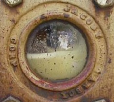 Figure 1. Cloudy condition in a sight gauge indicating moisture or air entrainment.
Inspection Step No. 5:
Figure 1. Cloudy condition in a sight gauge indicating moisture or air entrainment.
Inspection Step No. 5: Check for foul odors. For sumps containing EP and AW-type lubricants, water entrainment can lead to chemical changes that convert zinc-sulfur-phosphorus-based chemistries into sulfur-based acids and gases. The prime indicator is the strong and objectionable odor of rotten eggs noticeable with only slight wafting of the fumes off of the exhaust vent port.
Obvious vapor emissions. Any evidence of vapors rapidly emitting from the vent port may be a secondary indication of one of the previously noted problems or the indication of vaporization of the lubricant oil itself.
Observed vaporous emissions from normally hot machines (gas turbines, combustion engines) could indicate either oil or water vapor release. Since engine oils retain water normally through their high concentration of dispersant additives, one could expect engine sumps to drive off water for a few minutes after the oil reaches full operating temperature. Prolonged production of vapor (visual, olfactory observation), however, suggests that water is being introduced as rapidly as it is driven off.
Inspection Step No. 6: Check for coolant system internal leaks. Coolant system leakage can be confirmed with laboratory-based spectrometric and infrared spectroscopy, glycol analysis and level checks on the coolant system.
Some machines—such as gas turbines, synthetic fiber manufacturing machines, paper machine dryer bearing circulation systems and high ratio-high thermal rating gear drives—can produce temperatures hot enough to drive off any residual light hydrocarbons left from the base oil refining process. This would be characteristic of sumps operating at or above 100 C and producing vapors with strong petroleum odors.
Inspection Step No. 7: Check for level changes and oil darkening, and conduct laboratory testing. Loss of light-ends could be confirmed with chromatographic contrast of the in-use and the new lubricant states.
COLLECTED SAMPLES
Following the recognition of any of the conditions from the examples given above, a sample should be collected in a clear sample container. For our purposes, a plastic bottle would be best.
For visual inspections, the sample should immediately be observed for the initial signs of change. The in-use sample is first compared to a sample of the same oil in its new condition. This is done by holding the two samples side-by-side with a strong backlight. Is the oil clear and bright, and has there been any color change? If the answers are Yes and No, respectively, then testing is done. If the oil is not clear and bright, or there is a noticeable color change, go to the next step.
Before proceeding, if the sample has been pulled for more than a couple hours it should be warmed again. Allow the sample to sit for a couple hours under a high-intensity light or use a hotbox to rewarm the sample.
It is necessary to try to characterize the observed change. If the oil has experienced a distinct color change, it should be characterized according to a scale. Lubricants darken as they age. Some lubricants darken simply by exposure to light.
A change in color alone does not mean the lubricant is damaged. However, depending on the extent of color change in a single measurement interval, alarm might be warranted. Using the example of the ASTM Color Comparator, as shown in Figure 2, an immediate increase of two or more grades (0. 5 to 1.5 or 1.5 to 3.5) is too much change (assuming a sample interval of +/-10 days) and warrants a longer look. This degree of change in a 10-month cycle would not elicit the same response as the same change in a 10-day cycle.
 Figure 2. A well-defined color rating system helps minimize subjectivity in visual observations. (Courtesy of Trico Corp.)
If the change has been more than two steps, a blotter paper test should be performed. The blotter test is a form of chromatography without the use of a solvent. For this test, a single drop of warm oil is placed on a patch of blotter paper that is elevated to avoid contact with the flat surface.
A specialized coated substrate such as the CircOil test provided by Condition Monitoring International, as shown in Figure 3, is an excellent tool for this activity. The drop of hot oil travels through the paper by capillary action and forms concentric circular patterns that identify a variety of oil conditions. Oxidation, water contamination, lubricant cross contamination, sludge formation, high wear debris and loss of dispersancy are all patterns that can be recognized with blotter testing.
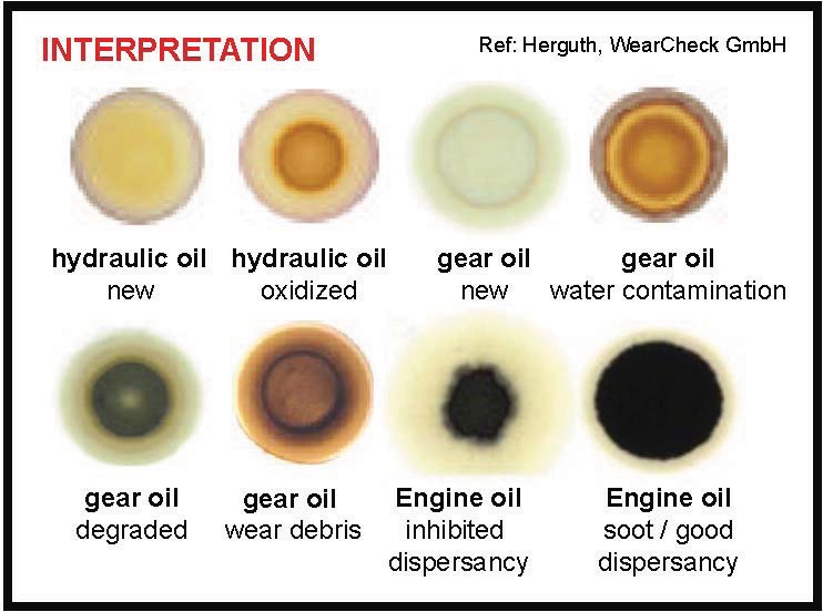 Figure 3. A visual blotter test reveals a variety of problem types. (Courtesy of Condition Monitoring International)
If haziness or cloudiness seemed apparent from the initial observation, then a crackle test is due. The crackle test may be conducted with a laboratory hotplate, an electric stove burner and skillet or just a spoon and lighter. The crackle test entails using heat to convert entrained water from liquid to gas by vaporization. The test temperature should be hot enough to cause instantaneous change, which produces a popping effect similar to that of water sprinkled into hot cooking oil.
Presence of an audible crackle indicates that there is enough water to report a problem and take action. Finite bubbles without audible sound is enough to justify additional investigation. Figure 4 illustrates the stages of water intrusion and visually what those stages might look like in a hotplate crackle test.
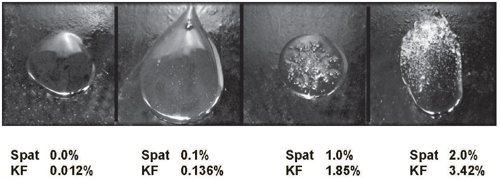 Figure 4. Multi-stage crackle test comparison.
Next, hold the sample up and observe the bottle bottom. Is there any evidence of sediment? If so, apply a strong magnet to areas around the sediment and look for movement. If movement occurs, then it is likely that a portion of the sediment is ferrous. A follow-up step would include sending the sample to a lab for a detailed analysis.

 Much can be determined about changing machine conditions from oil analysis by simple, subjective, intuitive observations.
Additionally, revisit the question of odor. If the oil exhibited evidence of oxidation, and if the oil exhibited a crackle during the crackle test, there is a good chance that the odor will be strong. With the bottle open and two-feet away, slowly draw air off the top of the bottle with the wave of a hand. If no odor is detected, repeat the exercise giving closer proximity between the bottle and the nose. If the smell of rotten eggs mentioned previously is noticeable, then formation of strong acids during oxidation is likely. This would serve notice that the oil should be replaced following a system flush and the inspection interval shortened to avoid reoccurrence.
Last, return to the machine and very lightly pat the surfaces of the sump/tank housing below the expected oil level to check the temperature. Exposed fingers can tolerate surface heat approaching 150 F. If the machine surface is hot enough to burn after a couple seconds of contact, then the machine is hot enough to consider the use of a synthetic lubricant (if not already in place).
This judgment is based on anticipated increase in temperature between the surface and the internal oil temperature (+10 F to +15 F), and another increase between the oil temperature in the sump and oil temperature at the machine dynamic load zone (+10 F to +15 F). At these temperatures, oxidation stress and viscosity loss are both reliability concerns for the machine.
SAMPLE FREQUENCY
The central point of this type of machine and lubricant assessment is that high frequency, low-time intensity sensory reviews can reveal the leading edge of machine trouble conditions. The sample interval should be driven by the combination of machine criticality ranking and the operating mode.
•
Biweekly to monthly—slow shaft speeds, high loads.
•
Weekly—moderate shaft speeds, moderate to high loads.
•
Daily—high shaft speeds (turbomachinery).
SUMMARY
Much can be determined about changing machine conditions from oil analysis by simple, subjective, intuitive observations. Tests conducted at the machine include observations for proper sump level, large bubbles, tight foam, cloudiness, hot surfaces and odors.
If any of these conditions are suspected or observed, samples should be collected for further review at a workbench. Additional testing should include color comparison from the most recent sample, observation for sediment, blotter spot testing, crackle testing and observations for strong odors. Any positives from these tests should lead to follow-up actions by reliability management.
 Mike Johnson, CLS, CMRP, MLT, is the principal consultant for Advanced Machine Reliability Resources, in Franklin, Tenn. You can reach him at mike.johnson@precisionlubrication.com
.